
Spring 2016 SPARCCS Final Block Diagram
By Jeremy Seiden (Mission, Systems, and Test)
I review the final system block diagram (including subsystem block explanations) for the dosimeter/SEU-detector project.
By Jeremy Seiden (Mission, Systems, and Test)
I review the final system block diagram (including subsystem block explanations) for the dosimeter/SEU-detector project.

By Eric Hanna (Design and Manufacturing)
I review the process of creating the PCB layout from the completed schematic.
By Jeremy Seiden (Mission, Systems, and Test)
I walk through the software design on the dosimeter/SEU-detection instrument, from data flow block diagrams into packetization and reception at a ground research station.

By Eric Hanna (Design and Manufacturing)
We conduct a trade-off study to decide between a CCD FPV camera and a CMOS camera for detecting single-event upsets (SEUs).
Introduction
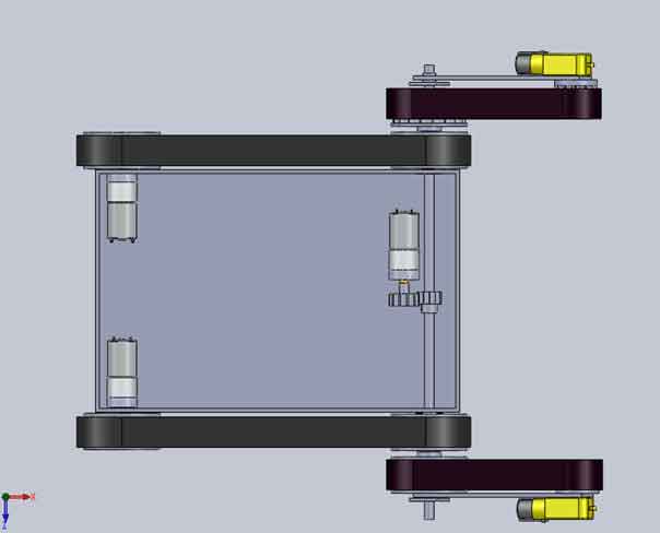
The design has changed for the last couple weeks. By assembling the 3Dot David, problems and issues occurred, and had to be adjusted, especially for the bottom plate, legs, and top plate.
Related requirement:
As part of the level 2 system requirement follows:
The 3DoT David shall use a 3D printed chassis and legs. This follows from the project level requirement about using 3D printed parts.
Table of Contents
Bottom Plate 1
The bottom plate below had some problems because the extrusion cuts made on those 10 holes. Placing the connection for the gears on those holes with the screw made the gears unstable and loose. In addition, the plank below on the right had to be super glued to the bottom of the bottom plate for 24 hours to cure. Some of the planks were easily broken off by drilling a hole on the bottom plate with the plank attached it. In the gear instability blog post on testing #1, this proves that the screws on those gears were interfering with the movements of the gears.


Bottom Plate 2
In solving the problems occurring in the 1st bottom plate, planks were then attached to the bottom plate. Gear instability was an issue. So making extrusions on the bottom plate, instead of extrusion cuts solved the issue of gear instability and movement of the gears. The holes on the bottom plate were made because the printing time exceeded 2 hours. With these holes, the printing time was exactly 2 hours.

Bottom Plate 3
The holes made on the bottom plate was not quite nice. So, “V” shaped extrusion cuts are made because they reduced less printing time, makes the design look nice. The two extrusion cuts are made for the new gearbox motors to be placed right at the bottom of it.

Bottom Plate 4
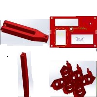
This is final design of the bottom plate. This is tested and assembled by the team. The changes made here are the 10 extrusions, where the gears are to be placed, to be 1 centimeters. The reason is the washer will be placed first, and then the gear will be placed second for it to freely rotate. In addition, securing the gears in place was an issue. To solve the issue, the use of the soldering iron will burn the 6 extrusions, where the large gears are placed, as it will form a surface that will secure it in place. Those semicircle holes are made to reduce the printing time, which came to exactly 2 hours. The motors are then attached to the bottom of the plate with a extra hole to secure the gearbox so that the motor does not move.

Previous top plate
The previous top plate measures to be 7 cm width and 12 cm length in order to fit the PCB and the 3Dot board on it. Each hole on each corner will connect the bottom plate with spacers and screws.The team thought of the battery on the 3Dot board because it can produce amount of heat to the top plate, which could melt it.

Final top plate
The final top plate is the same dimensions as the previous top plate. The only changes to it are making extrusion cuts in order to prevent the heat of the 3Dot board and PCB from touching the top plate. A hole is made so that the IR tube is screwed into it. Cables from the motor will go through the hole mentioned in the below figure. An extra extrusion cut is made to see the gears move for everyone to see.

Leg 1
As the team assembles the 3Dot David, connections that were made with the tibia and femur were blocking the movement of all the other legs. As a result of the tests that were made, the team decided to change the leg design to make sure there are no interferences with the movement.

Leg 2
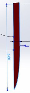
By making it as one piece and centering the tibia, no interferences will be made on the movement. However, it could not be printed because the height of the tibia was too high at 6.8 cm.

Leg 3
By making separate pieces of the leg, which are the tibia and femur, 3D printing will make it easier because the parts have a flat surface. The extrusion cut was made for the connection of the screw at 0.265 centimeters. Super glue will be added to secure them in place as it walks on the floor.


Previous Femurs
The previous femur had trouble stabilizing its weight as it walks. By attaching all the six femurs, it was not able to balance because of the 4 legs attached to the corner gears. However, this femur will be implemented into the middle gear of the gear train.

Adjusted femurs
With these two adjusted femurs, theoretically, the 3Dot David will not have trouble walking. The femurs would help it balance as it walks.


Implementing the femurs
By implementing the femurs into the bottom plate, the spider will balance itself, according to the figure below.

Adjusted tibia
The tibia had to be adjusted by adding 1.5 centimeters to 5.3 centimeters of the previous tibia. That is because the gearbox on the bottom of the bottom plate was almost touching the surface. By adding it, 6.8 centimeters is the length of the tibia that will solve the issue.
Conclusion
As the team solved issues with the bottom plate, legs, and top plate by assembling and testing them, the design evolved in that process. Costs and time took a lot in the process. However, the evolution of the design is an experimental process towards finding the final design by making extrusion cuts to lessen the printing time as well as making the design beautiful and stabilizing the spider by adjusting the femurs and bottom plate.

By:
Xiong Lee (Missions, Systems and Test)
System Block Diagram
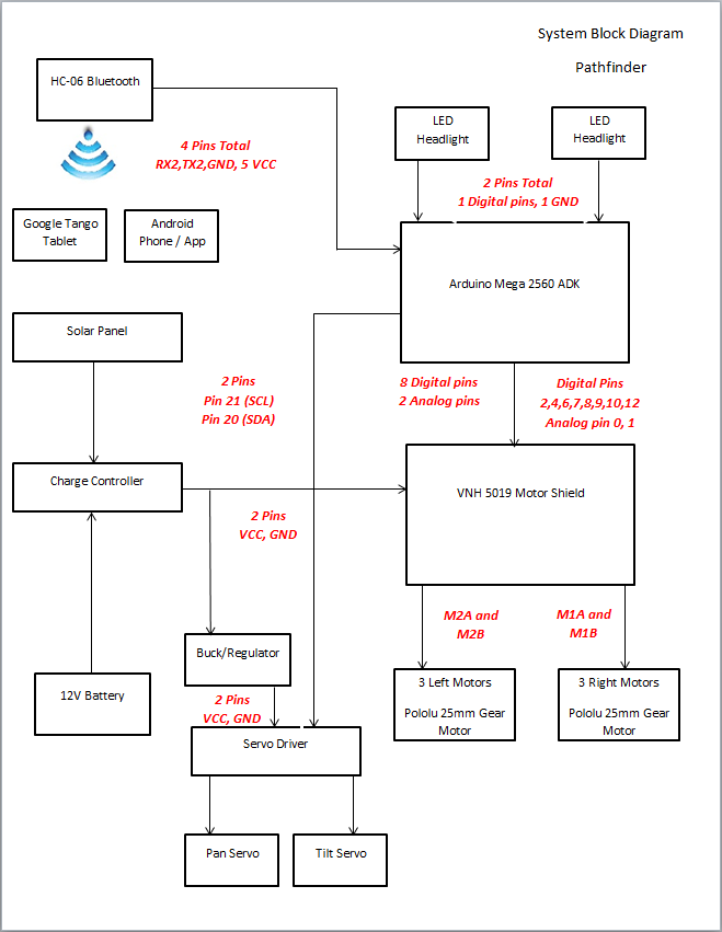
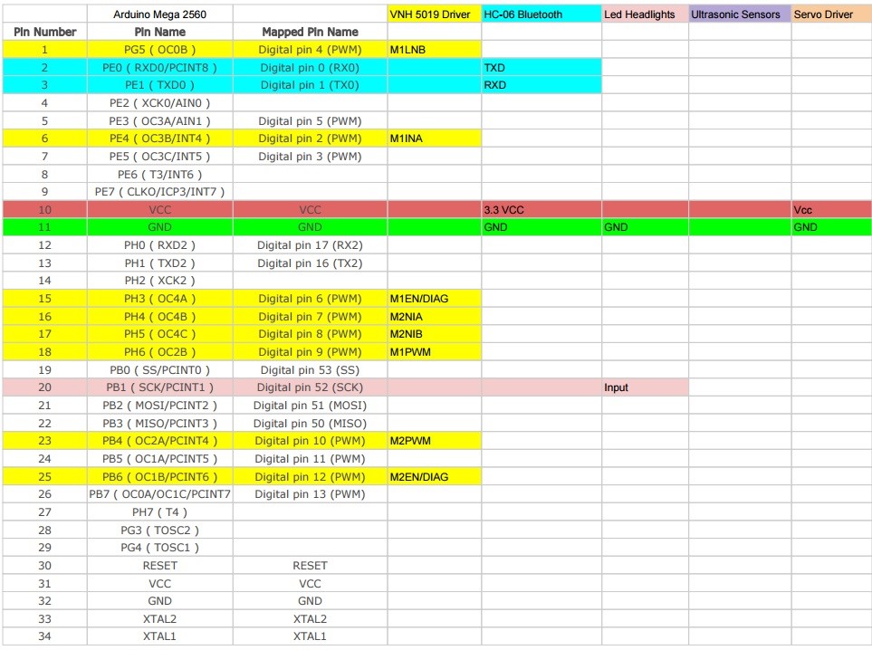
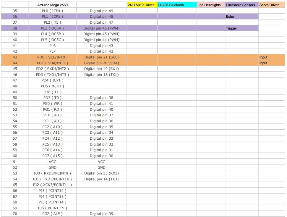
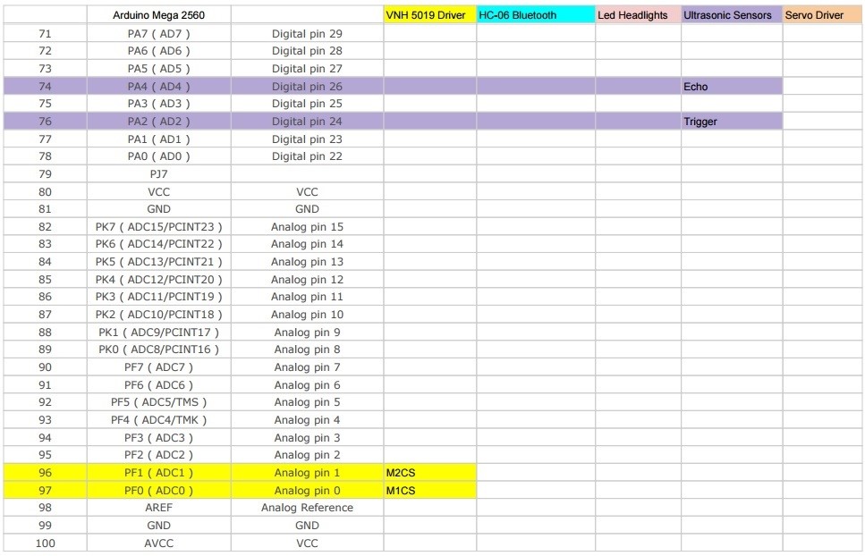
The picture above shows a block diagram of our pathfinder. These are the hardware that we are using to run our pathfinder. From this diagram, it shows how many pins we are allocating for each hardware. For example, we are using TX, RX, 5v, and Gnd for the bluetooth module (HC-06) that we are using. This shows each component we are using and what pins should be allocated to those specific component.
Here is a basic walkthrough of our project. We are using the arduino mega and we have the bluetooth module (HC-06) connected to the pins TX2, RX2, 5v, and Gnd. The arxterra app is then connected to the Google tango via wi-fi and the tango is connected to HC-06 via bluetooth. The next component we have is the LED’s. We allocated 2 pins total for these two LED. On top of our arduino is our motor shield. It is connected to 8 digital pins and 2 analog pins. The next thing connected to our arduino is the servo driver. We have allocated pin 21 and 20 for the servo driver. Through the servo driver, our pan and tilt servo is connected on it. On the side, we have our solar panel and battery connected to the charge controller and then the charge controller is connected to the motor shield and buck regulator. The buck regulator (step down voltage regulator) is then connected to the servo driver.
For more in depth view on which pins are used on the arduino, look at the interface definition table below.
These diagrams are our system block and interface diagrams. The only concluding though I have is to make these diagrams readable and easy for the eye during the presentation. This was one of the problems many groups had this semester. Other than that, the other groups also had good diagrams. If you need more references as to how you should do these diagrams, look at the other groups too.
The Rover should travel on level area, ramp area, and stair ways during the mission test.
By Dang Le, Project Manager
Program Objective/Mission Profile
Program Objective
The project objective is to build a rover that will simulate a flyer distributor advertising CSULB’s Eta Kappa Nu social, guest speaker, and technical events on campus. Using a single power source the rover will launch from, and return to, an HKN advertisement booth and run in a general high foot-traffic area on campus which consists of flat areas, sloping areas, and stair ways, as shown in the course map. The rover will be controlled remotely using a computer with internet connection. Negotiations of budget resulted in the rover to cost less than or equal to $250. There is to be expected 0 to 16 mph wind during the course run on May 13th (Reported in Weather Report).
Mission Profile
The total distance is approximated in 344fts. The perimeter of the grass is 275 ft / 84 m. The north and south sides are leveled. The east side has 9 steps. The west end is a ramp.
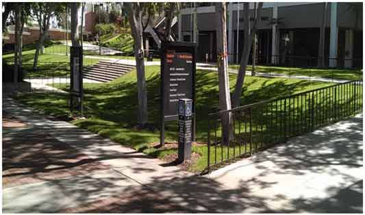
The front of USU building
The Design
The main component in our rover design are including
Project Features
Custom PCB Design
Fritzing diagram circuit with three H-bridge and I2C protocol IC to drive five motors with using Arduino and firmware coding.
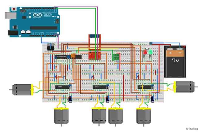
Fritzing Diagram
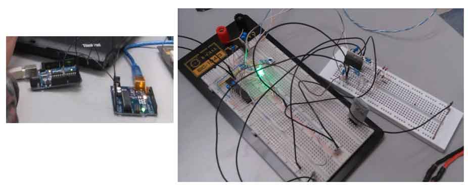
Breadboard testing transmit and received data with using H-bridge IC circuit and Arduino coding.
PCB layout

Hardware Design
By Muhammad Maqbool, Manufacturing Engineer
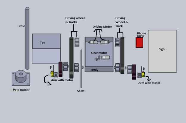
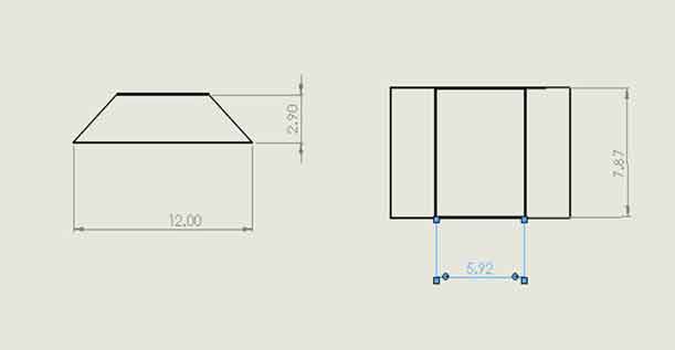
The body of our AdBot is set to be 12” x 8” x 2”. The Body is made of Aluminum. I got separate sheets of Aluminum each with a thickness of 0.125 inch and I welded them together with the help Ryland Walts. The reason for choosing Aluminum is that for our AdBot we wanted a strong body that would not get damaged if our AdBot hits the stairs or anyone try to kick it.
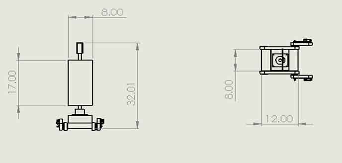
The body consist of two holes in the back each of a diameter of 0.16 inches, the holes provide a path for the driving motors to directly connect with the wheel. The two holes in the front of the body provides a path for the shaft to pass through and will be connected to the free moving wheels and arms.
The wheels are printed using ABS plastic. ABS plastic is the most cost effective material. Each Wheel has a diameter of 2.5 inches and a thickness of 0.7 inch. The arms of the our AdBot will be of Aluminum as wheel, the arms will be 6” x 1” with a thickness of 0.125 inch. We have two motors in the front of the arm that will be driving the front wheels at all times. I have designed the gear for the shaft and the motor myself. As the motor rotates the gear on it rotates with it hence rotating the gear on the shaft and lifting the arms. I have designed two arm holder myself that will hold the arm on the shaft at all times.
The top of our AdBot is more aerodynamic by adding curves to it so it can go fast. The top is 12” x 8” and will sit on the body and I will screw them both. I will design a pole holder that will hold our pole hence holding our sign.
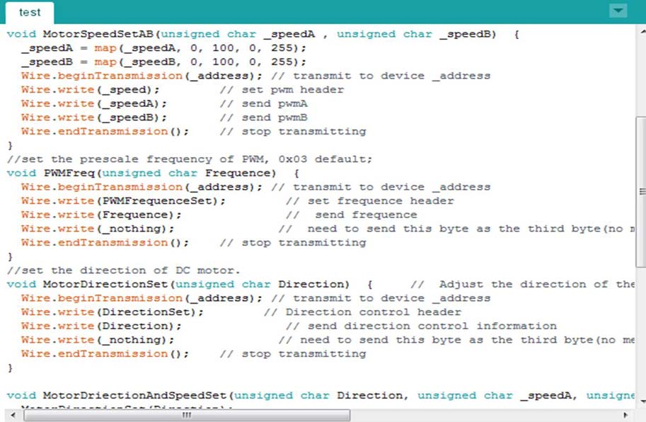
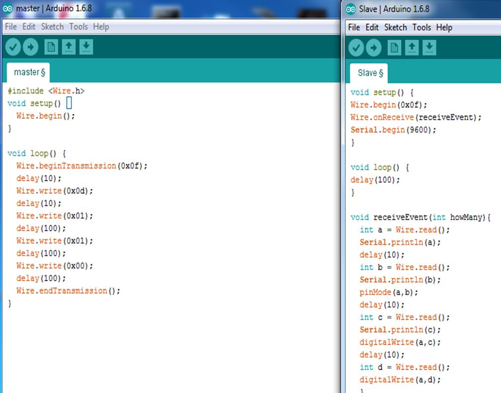
Test code for controlling motors with Arxterra Application
By Dang Le, Project Manager
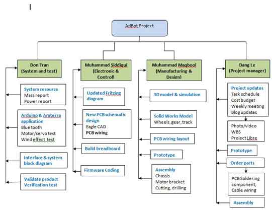
Work Breakdown Structure (WBS)
As a project manager, who created and assigned tasks for each member within the team throughout the project. A work breakdown structure (WBS) that showed each of team member who had responsible for their tasks. There could be a change during the mission task depend who has more free time and ability to take workload from other member. Here is our delegation tasks that showed in display below.
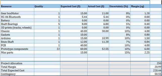
Budget Report updated
As a Project manager, I have to keep track on our budget to make sure it still within our given budget. The most expense is on prototype component and chassis. Unfortunately, our rover were bigger compare to previous semester, thus we have to look for the difference type of tracks that can support our rover during the mission test course. First, we thought we could use 6V DC motor for our rover ( these motor are free from previous semester), but now due to the rover is too heavy and may not be able to travel on stair ways and long distance, so we may replaced with 12V DC motor for final demo. Our budget report with expected cost right now without five of 12 V DC motors is $220.44.
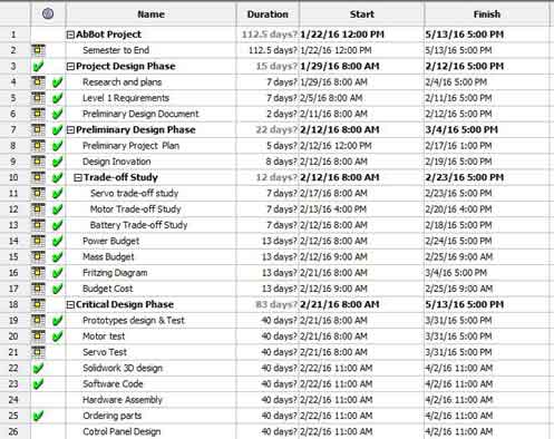
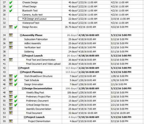
Schedule Updated
Project schedule is the software that used to create a task schedule and plan in this project for a specific date to be completed. As the project moved on, we could see which tasks we were completed or behind the schedule. The schedule showed in green check mark that indicated these tasks were completed. However, the main concern was the PCB schematic and PCB wiring layout. We have built a new schematic, which more complicated than our thought due to more parts on PCB and not enough clearance between one trace to another, thus our team member were having so much trouble when doing the layout. Furthermore, we were down by one of our team member electronic engineer. Thus, we were behind the schedule as our planned. Another issue was main tracks for our rover. The current track we have as the same last semester that was not support enough for our rover during the mission test. We are still looking for the tank track and 12 V DC motor with high torque for our AdBot.
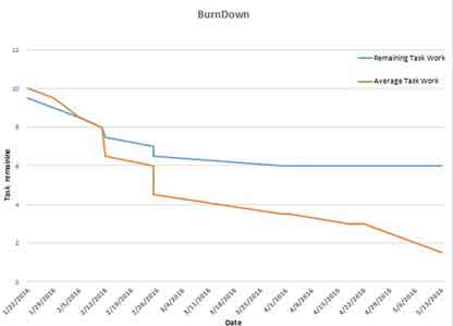
Status and Percent Complete
Here is the status and percent burn down as we move along until this time. The charts showed that we were behind on software coding, PCB layout, and hardware as well.

click the link below to watch the AdBot demonstration
https://www.youtube.com/watch?v=CX5fDNFeUjc

By:
Juan Acosta (Electronics & Control – MCU Subsystem and Firmware)
Table of Contents
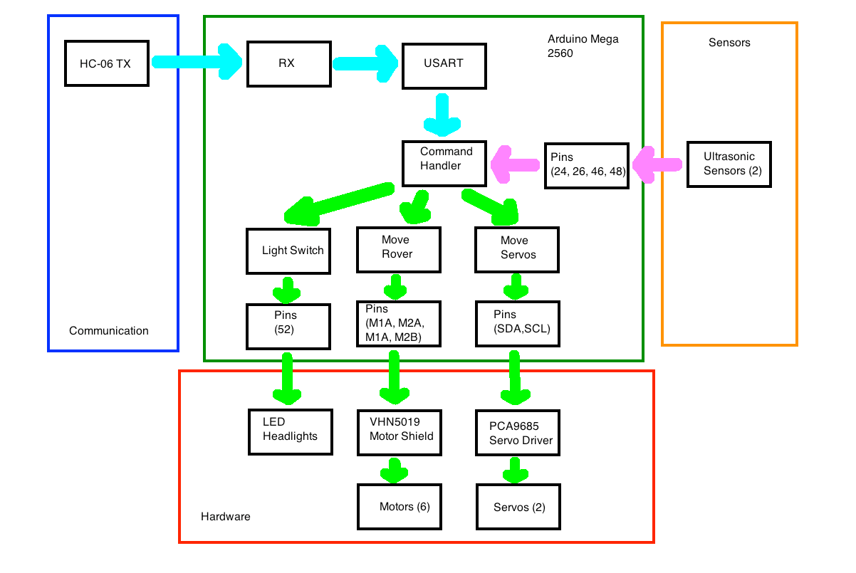
The figure above depicts the software side of the Pathfinder. First, commands will be sent through Bluetooth and received through Serial communication ports on the Arduino Mega. Then the Command Handler will decode the telemetry packets being sent and appropriate an action unique to each packet ID. The VHN5019 Motor shield will implement the movement of the Pathfinder. The PCA9685 Servo driver will control the pan and tilt servos. Additionally, the use of ultrasonic sensors will provide feedback for obstacle detection or collision. Lastly, we will create a custom Arxterra command to control our L.E.D. headlights.
The following code snippet was used to test the functionality of the PCA9685 Servo Driver and how to gain a better understanding for servo control. For testing purposes, we used the Coolterm application on a laptop to demonstrate wireless bluetooth control of the servos. The code provided will help future projects in the process of initializing bluetooth communication, transmission of data, and later the creation of custom Arxterra commands.
///////////////////////////////////////////////////////////////////////////////
// The following code was written, tested and debugged by Juan Acosta for
// testing pan and tilt servo control through two wire communication (I2C)
// using the HC-06 to implement commands being sent from the COOLTERM application
// from a laptop or phone to the arduino.
// Group: Pathfinder Spring 2016
// Electronics and Control: Juan Acosta (MCU Subsystem and Control Firmware)
///////////////////////////////////////////////////////////////////////////////
#include <Wire.h>
#include <Adafruit_PWMServoDriver.h>
///////////////////////////////////////////////////////////////////////////////
// following are connections required for HC06 module:
// connect BT module TX to RX0
// connect BT module RX to TX0
// connect BT Vcc to 5V, GND to GND
///////////////////////////////////////////////////////////////////////////////
// following are connections required for PCA9685 Servo Driver:
// connect V+ to 5V, GND to GND (servo power terminals)
// connect Vcc to 5V, GND to GND
// connect SDA to analog pin A4 (required for I2C bus control on arduino UNO)
// if using arduino MEGA SDA has dedicated pin on PIN20
// connect SCL to analog pin A5 (required for I2C bus control on arduino UNO)
// if using arduino MEGA SCL has dedicated pin on PIN21
// connect pan servo plug to 9
// connect tilt servo plug to 11
///////////////////////////////////////////////////////////////////////////////
Adafruit_PWMServoDriver pwm = Adafruit_PWMServoDriver();
#define SERVOMIN 0 // this is the ‘minimum’ pulse length count
// (for Pan = facing left)(for tilt = facing down)
#define SERVOMAX 500 // this is the ‘maximum’ pulse length count
// (for Pan = facing right)(for tilt = facing up)
// The limits for the pan will be from 0 degrees to 180 degrees of view in steps
// of 45
// The limits for the tilt will be from 45 degrees to 135 degrees of view in
// steps of 45
void setup() {
Serial2.begin(9600); // set the data rate for the Serial Port
pwm.begin();
pwm.setPWMFreq(60); // Analog servos run at ~60 Hz updates
yield();
}
// Character commands list:
// (“Send ‘0’ pan facing left (180 degrees)”);
// (“Send ‘1’ pan facing diagonal left (135 degrees)”);
// (“Send ‘2’ pan facing center (90′ degrees)”);
// (“Send ‘3’ pan facing diagonal right (45′ degrees)”);
// (“Send ‘4’ pan facing right (0′ degrees)”);
// (“Send ‘5’ tilt facing down (-45 degrees)”);
// (“Send ‘6’ tilt facing center (0 degrees)”);
// (“Send ‘7’ tilt facing up (45 degrees)”);
char a; // stores incoming character from other device (phone, tablet, or laptop)
void loop()
{
if (Serial2.available()) // if text arrived in from hardware serial…
{
a=(Serial2.read());
if (a==’4′) // face right
{
Serial.println(” pan facing right (0′ degrees)”);
for (uint16_t pulselen = SERVOMIN; pulselen < SERVOMAX; pulselen++) {
pwm.setPWM(9, 0, pulselen);
}
delay(1000);
}
if (a==’3′) // face right at an angle (diagonal right)
{
Serial.println(“pan facing diagonal right (45′ degrees)”);
for (uint16_t pulselen = SERVOMIN; pulselen < 375; pulselen++) {
pwm.setPWM(9, 0, pulselen);
}
delay(1000);
}
if (a==’2′) // face straight (centered)
{
Serial.println(“pan facing center (90′ degrees)”);
for (uint16_t pulselen = SERVOMIN; pulselen < 250; pulselen++) {
pwm.setPWM(9,0,pulselen);
}
delay(1000);
}
if (a==’0′) // face left
{
Serial.println(“pan facing left (180 degrees)”);
for (uint16_t pulselen = SERVOMAX; pulselen > SERVOMIN; pulselen–) {
pwm.setPWM(9, 0, pulselen);
}
delay(1000);
}
if (a==’1′) // face left at an angle (diagonal left)
{
Serial.println(” pan facing diagonal left (135 degrees)”);
for (uint16_t pulselen = SERVOMAX; pulselen > 125; pulselen–) {
pwm.setPWM(9, 0, pulselen);
}
delay(1000);
}
if (a==’5′) // face down (-45 degrees)
{
Serial.println(“tilt facing down (-45 degrees)”);
for (uint16_t pulselen = SERVOMAX; pulselen > 125; pulselen–) {
pwm.setPWM(11, 0, pulselen);
}
delay(1000);
}
if (a==’6′) // face straight (centered)
{
Serial.println(“tilt facing center (0 degrees)”);
for (uint16_t pulselen = SERVOMIN; pulselen < 250; pulselen++) {
pwm.setPWM(11,0,pulselen);
}
delay(1000);
}
if (a==’7′) // face right at an angle (diagonal right)
{
Serial.println(“tilt facing up (45 degrees)”);
for (uint16_t pulselen = SERVOMIN; pulselen < 375; pulselen++) {
pwm.setPWM(11, 0, pulselen);
}
delay(1000);
}
if (a==’?’) // commands list
{
Serial.println(“Send ‘0’ pan facing left (180 degrees)”);
Serial.println(“Send ‘1’ pan facing diagonal left (135 degrees)”);
Serial.println(“Send ‘2’ pan facing center (90′ degrees)”);
Serial.println(“Send ‘3’ pan facing diagonal right (45′ degrees)”);
Serial.println(“Send ‘4’ pan facing right (0′ degrees)”);
Serial.println(“Send ‘5’ tilt facing down (-45 degrees)”);
Serial.println(“Send ‘6’ tilt facing center (0 degrees)”);
Serial.println(“Send ‘7’ tilt facing up (45 degrees)”);
}
// you can add more “if” statements with other characters to add more commands
}
}
The following code snippet was used to demonstrate the functionality of the VHN5019 Motor shield and how to gain a better understanding of DC motor control. For testing purposes, we used the Coolterm application on a laptop or cell phone to demonstrate wireless bluetooth control of the pathfinder’s movements. The code provided will help future projects in the process of initializing bluetooth communication, transmission of data, and later the creation of custom Arxterra commands.
///////////////////////////////////////////////////////////////////////////////
// The following code was written, tested and debugged by Juan Acosta for
// testing the functionality of the VHN5019 Motor Shield and how the six motors
// rotate will dictate which way the rover moves.
// using the HC-06 to implement commands being sent from the COOLTERM application
// from a laptop or phone to the arduino.
// Group: Pathfinder Spring 2016
// Electronics and Control: Juan Acosta (MCU Subsystem and Control Firmware)
///////////////////////////////////////////////////////////////////////////////
#include “DualVNH5019MotorShield.h”
DualVNH5019MotorShield md;
void stopIfFault()
{
if (md.getM1Fault())
{
Serial.println(“M1 fault”);
while(1);
}
if (md.getM2Fault())
{
Serial.println(“M2 fault”);
while(1);
}
}
void setup()
{
Serial.begin(115200);
Serial.println(“Dual VNH5019 Motor Shield”);
md.init();
Serial.begin(9600);
}
char a; // stores incoming command from device into variable a
void loop()
{
if (Serial.available())
// if text arrived in from hardware serial…
{
a=(Serial.read());
if (a==’?’)//////// send commands list
Serial.print(“Send a 1 to move the pathfinder forward”);
Serial.print(“Send a 2 to stop the pathfinder”);
Serial.print(“Send a 3 to rotate the pathfinder by 180 degrees”);
Serial.print(“Send a 4 to make the pathfinder reverse”);
if (a==’1′)/////// move the pathfinder forward by sending a 1
{
int o=0; /////// stop the rover before moving forward
md.setM1Speed(o);
md.setM2Speed(o);
for (int p = 0; p <= 300; p++)
{
md.setM1Speed(p);
md.setM2Speed(p);
Serial.print(“Moving the Pathfinder forward “);
}
}
if (a==’2′)///////////////// stop the wheels by sending a 2
{
int i=0;
md.setM1Speed(i);
md.setM2Speed(i);
Serial.print(“Stop the Pathfinder: “);
}
if (a==’3′)///////////////// rotate 180 degrees
{
Serial.print(“Rotating 180 degrees “);
int c=0;////////////////// stop rover before rotating
md.setM1Speed(c);
md.setM2Speed(c);
for (int m = 0; m <= 300; m++) //////// rotate rover 180 degrees
{
md.setM1Speed(m);
md.setM2Speed(m-300);
delay(2.3);
int k=0;
md.setM1Speed(k);
md.setM2Speed(k);
}
}
if (a==’4′)/////// make the pathfinder reverse by sending a 4
{
Serial.print(“The pathfinder will reverse”);
int l=0; /////// stop the rover before reversing
md.setM1Speed(l);
md.setM2Speed(l);
for (int j = 0; j <= 300; j++)
{
md.setM1Speed(j-600);
md.setM2Speed(j-600);
}
}
}
}
Applying what we now have learned, we are ready for software implementation through Arxterra including custom commands. Once we had each module working separately, putting them all together to form the pathfinders software system design will require a reasonable amount of testing and debugging since we now have most of it done working without Arxterra. All that is left is the custom command encoding.
– Coolterm:
http://freeware.the-meiers.org
– Spring 2016 Pathfinder: Subsystem Design
http://arxterra.com/spring-2016-pathfinder-subsystem-design/
– Arxterra Custom Commands
IR Emitter/Receiver Study
Introduction:
This is an overview of the trade-off study conducted for the selection of our IR emitter/receiver system. We will being going over the characteristics of each component that were taken into consideration while gathering information, as well as solutions to creating the ideal IR system. In addition, there is a link in the resources section that we used to understand the datasheet specs.
Note: There were no actual specifications for the IR system. The following results are what we believe to be the most optimal for our project.
Emitter:
Ideal Characteristics:
Results:
![]()
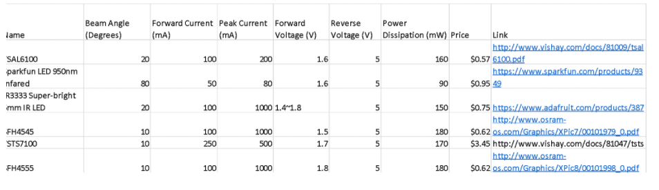 Fig. 1: Table of appropriate IR emitters)
Receiver
Ideal Characteristics:
Results:
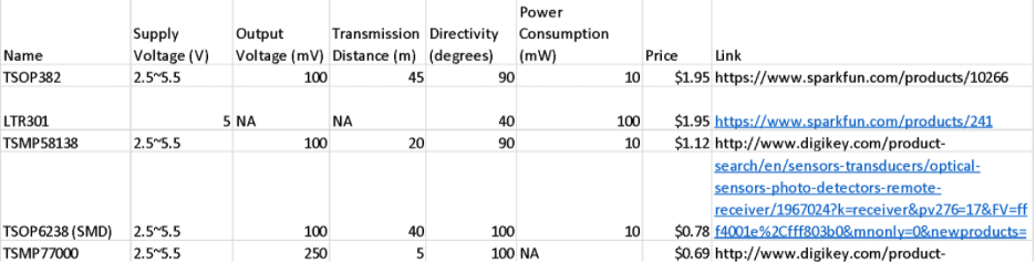
(Fig. 2: Table of appropriate IR receivers)
Conclusion
Update:
Kent was given a SFH310 for the detector and a NTE30047 for the emitter in order to test how each component was working. The beam angle is a bit wider on the emitter he was given but it will work fine for our game of tag when combined with a lens. The purpose of the lense is to increase the overall range and increase the accuracy of the emitter. See the IR/Emitter blog post to see my research on the effect of lenses on IR emitters. The lenses have yet to arrive, but when they do he will begin testing to see if the range increased and determine what the voltage rating is at the further distances.
Resources:
Understanding Diode Ratings | http://www.allaboutcircuits.com/textbook/semiconductors/chpt-3/diode-ratings/
DIY Laser Tag | http://www.lasertagparts.com/mtoptics.htm
Christopher Andelin (Project Manager)
Mario Ramirez (Systems Engineer)
Qui Du (Manufacturing Engineer)
Andrew Laqui (Electronics and Controls Engineer)
Henry Ruff (Electronics and Controls Engineer)
Table of Contents
By Andrew Laqui (Electronics and Controls Engineer)
The Fritzing software, found here , allowsa physical breadboard design to be created digitally. By designing a digital version, the beginning PCB designs can begin. One difficulty with using the free software is that the library does not have all the parts needed for many designs. Using Google, many of the parts required were found with Github.
Here are links to the Fritzing libraries for RoFi:
https://github.com/adafruit/Fritzing-Library (If using the Adafruit Servo Driver)
https://github.com/RafaGS/Fritzing (For the Bluetooth Module HC-06 and Accelerometer/Gyroscope MPU-6050)
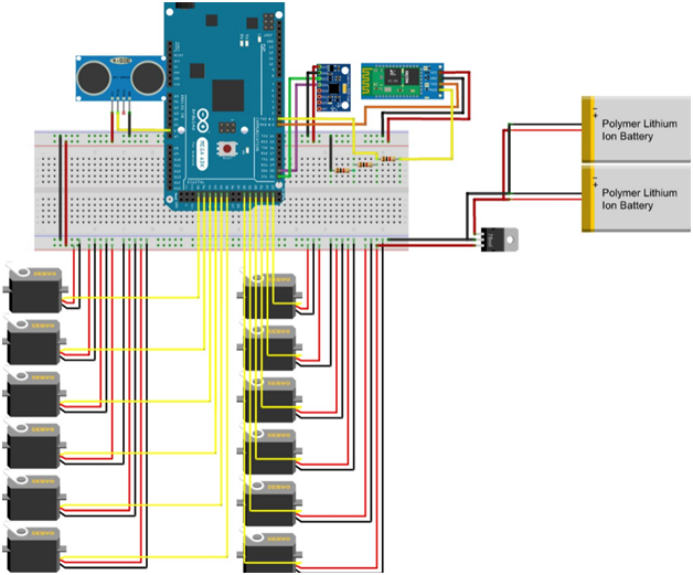
Figure 1: Fritzing Diagram
The image below shows what the PCB will be replacing. Just having twelve servos without any of the other components creates quite a messy board; especially on the Arduino MEGA, wires would often come out and cause a servo to stop working. The new PCB allows the servos to be easily plugged in while keeping the wires from becoming tangled.
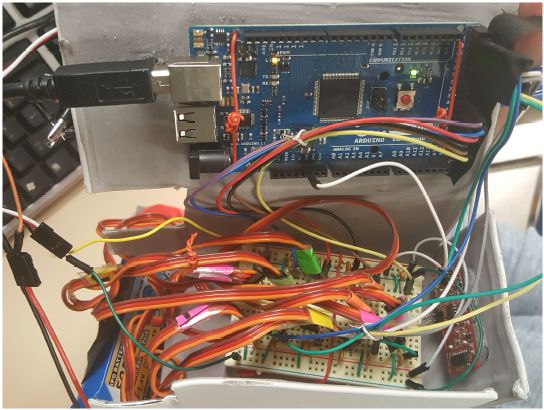
Figure 2: Prior to PCB Implementation
By Andrew Laqui and Henry Ruff (Electronics and Controls Engineer)
Due to the requirement to use a smaller Arduino microcontroller than the Arduino MEGA, we originally thought that we had to implement something like the Arduino Uno or Nano. We were later informed that rather than designing a shield as our printed circuit board for the Arduino, we could implement the chip used in the MEGA. After learning that the ATmega1280 is the correct chip to use to control RoFi, the group decided that this would a great way to design our PCB; the PCB design was challenging while also allowing us to continue to use the software made available on the Project.

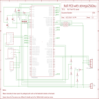
Figure 3: PCB Schematic
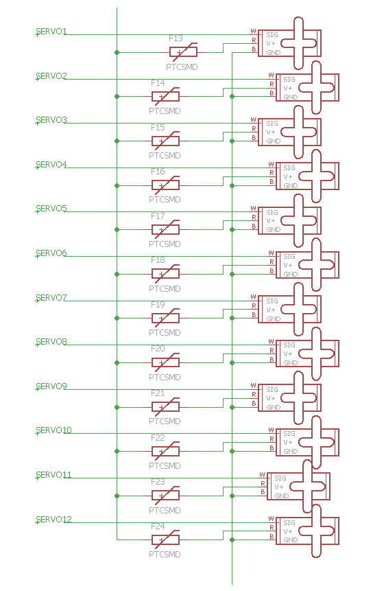
Figure 4: Servo Schematic
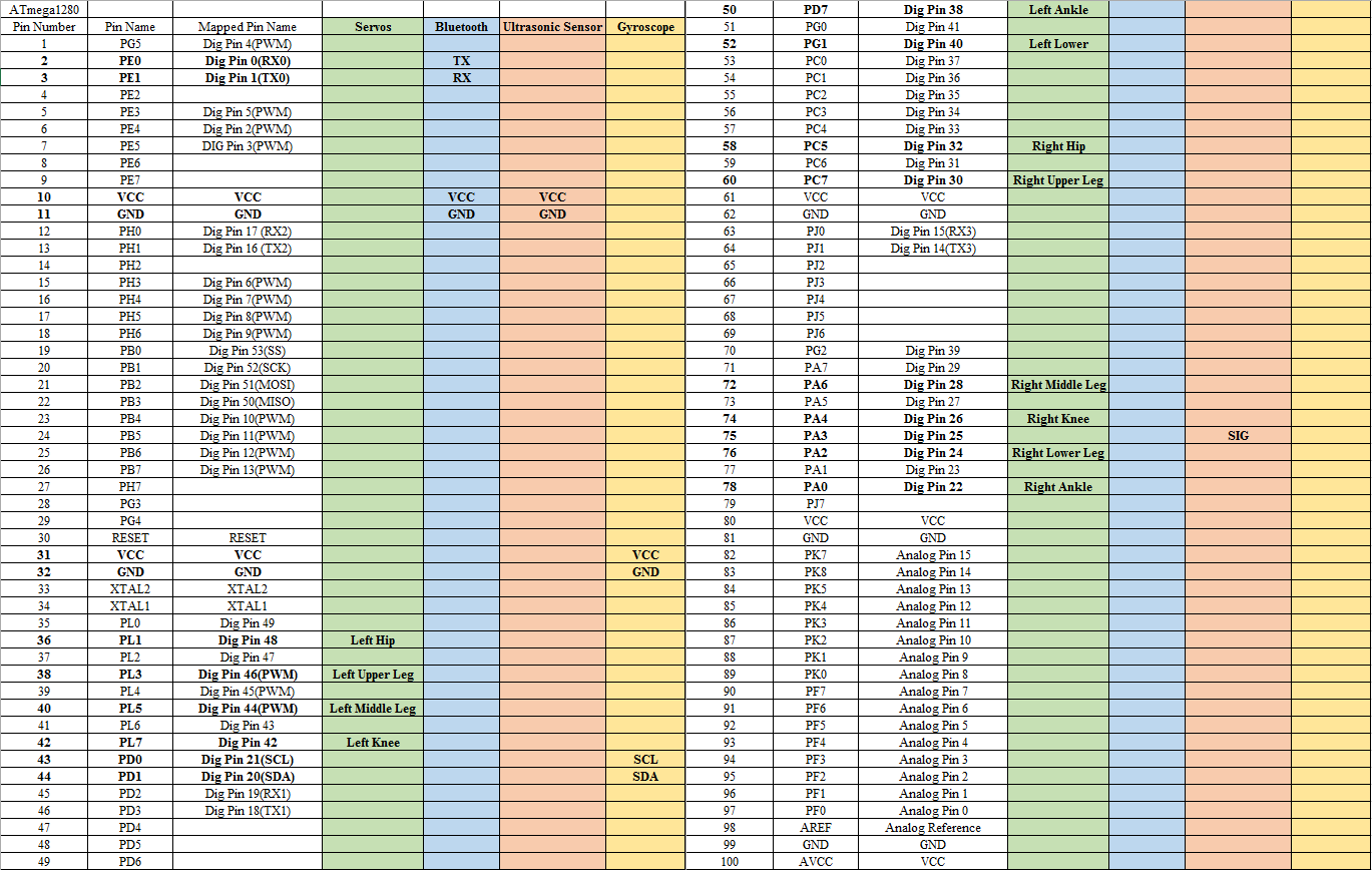
Figure 5: Interface Definitions
For the ATmega1280 itself, the footprint and pin connections are identical to the ATmega2560, and so this was able to be used for the EAGLE layout. Necessary protection circuits were included by following the schematic from Arduino’s website, but an additional 6-pin header was added for the bootloader necessary for the chip. A 6-pin header was added for the FTDI component, which would be used to allow for the USB port to be programmable. Additionally, there are two separate voltage divider circuits, one to allow for the 3.3V that the Bluetooth and MPU-6050 use, and one for the RX line of the Bluetooth. A simple 3-pin header is used for the power input, coming from the external voltage regulator that is connected to the batteries.
Once the interface definitions were developed, connecting the pins using EAGLE was simple. In order to keep the EAGLE schematic looking neat and legible, we used a second page for the servos. By changing the name of the wires, the wires can be connected across different pages. It is important when changing the name of the wires to put a note on the wire that is being named so that the pins from the ATmega1280 are clearly shown. Another issue we were having was that on the second page with the servos, a few of the VCC and GND wires looked like they were connected to the servo, but in reality, they were not actually connected. Once we were sure that all of the pins were connected properly, the layout was easily completed.
By Henry Ruff (Electronics and Controls Engineer)
For the option of using an Arduino board aside from the Mega, there are some considerations. First of all, there will not be enough pins to accommodate all of the sensors and the 12 servos, so a servo driver would be needed for the servos. An early PCB design utilized the Adafruit 16-Channel 12-bit PWM/Servo Driver, as shown in the following image.
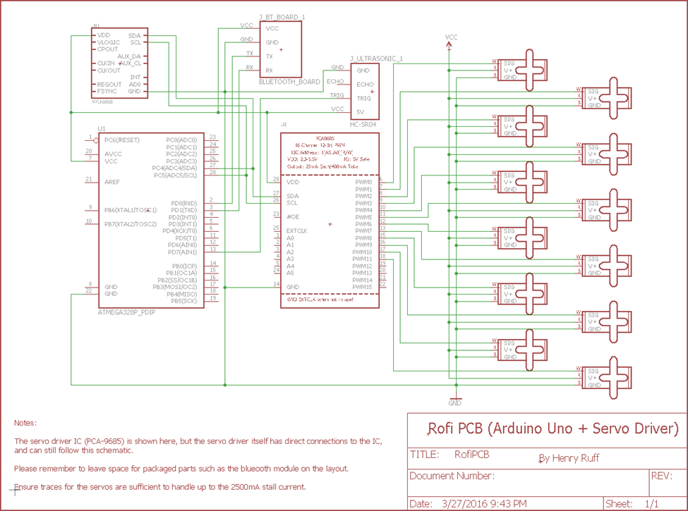
Figure 6: Arduino Uno and Servo Driver Schematic
However, further complications were found when working with Robot Poser. The source code was never made available, so there was no room for modifications. The real problem was in the “Rofi.RobotProfile” file that Robot Poser uses, there is direct addressing of pins that can only be found on an Arduino Mega.
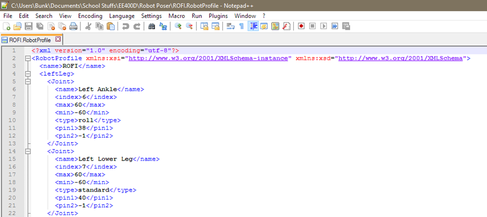
Figure 7: Robot Profile
In the servo driver code, its method of addressing a particular servo is by using a variable, as shown in Figure 8. This conflicts with the method that Rofi.RobotProfile uses, and since Robot Poser itself cannot be modified, using anything but the Arduino Mega while also using Robot Poser is simply not possible. These complications were primary factors leading to us implementing the ATmega1280 chip directly onto the PCB instead of using a different Arduino.
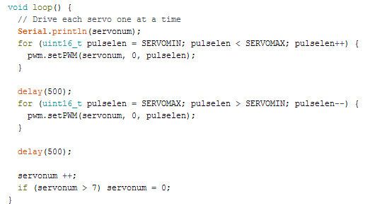
Figure 8: Servo Driver Code
By Henry Ruff (Electronics and Controls Engineer)
To simplify the PCB design and make it easier for future renditions of RoFi, we created custom EAGLE components for the Invensense MPU-6050 Accelerometer/Gyroscope and the SEN136B5B Ultrasonic Sensor. The former has a space laid out for it to be placed directly above the PCB, while the latter is ideal at the edge of the PCB as it can stick out due to its right-angle headers. These files were consolidated into a custom RoFi library that can be added to EAGLE, and is available below.
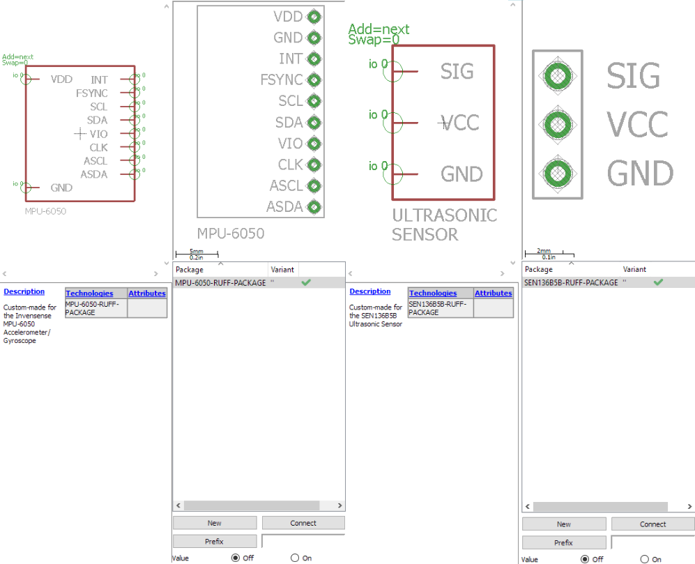
Figure 9: Customer Eagle Components