
Spring 2018 3DoT Hexy: Final Project Summary
By: Eduardo De La Cruz (Project Manager & Manufacturing Engineer)
Approved By: Miguel Garcia (Quality Assurance)
SpiderBot Team:
Eduardo De La Cruz (Project Manager & Manufacturing Engineer)
Raymundo Lopez-Santiago (Mission, System, and Test Engineer)
Kris Osuna (Electronics and Control Engineer)
Table of Contents
Mission Objective
For the Spring 2018 3DoT Hexy SpiderBot project, under the EE400D program, we will incorporate Arxterra’s 3DoT Robotics microcontroller board to design, build, and remotely operate a toy for people ages 8+. Control of the 3DoT Hexy SpiderBot will be accomplished via the Arxterra Mission Control Panel and/or ArxRobot application. 3DoT Hexy SpiderBot is to navigate remotely through a custom-built maze, memorize the path it took, start over, and autonomously travel through the path it took. The 3DoT Hexy SpiderBot is to have the ability to avoid collisions if it encounters other robots in the maze. The overall project is to remain within budget of $250 and be completed by May 15, 2018.
Level 1 and Level 2 Requirements
Level 1 requirements are high level requirements and are broken up into general requirements and specific robot requirements for 3DoT Hexy. All level 1 requirements are branched out to specific system and subsystem requirements (level 2 requirements).
https://www.arxterra.com/spring-2018-3dot-hexy-level-1-and-level-2-requirements/
System Design
System Block Diagram
Due to changes in the maze printing material and the fact that we are no longer using a boost converter, the UV LEDs will no longer be used and instead IR LEDs along with Light sensors will be used to handle intersection detection. Another change that is noticeable is instead of using an 8-channel I2C expander, we are now using a 4-channel I2C expander. The color sensor was removed from the design since we are using light sensors for intersection detection. A new addition to the design is the use of a gyroscope to aid in directional turning and two LEDs to act as eyes of the spider robot. The interface matrix was updated to reflect changes. Only 8-pins from the bottom shield of the 3DoT board will be used.
https://www.arxterra.com/spring-2018-3dot-hexy-system-block-diagram/
Experimental Results/Research
UV Trade Study
The original idea for the autonomous navigation of the maze was to have 3DoT Hexy take a picture, process the image and decide its action based on the image. The camera idea was proven to be too extensive with a high learning curve, so we decided to research other methods for the autonomous navigation through the maze. We decided to look into UV sensors to detect and follow a UV marker line. Since we were not going to use 5V to drive the LEDs, we changed UV LEDs to IR LEDs since the data shows that the UV sensors can not accurately differentiate when the UV LEDs are powered by 3.3V.
https://www.arxterra.com/spring-2018-3dot-hexy-uv-sensors-study/
Motor Type selection and Testing
Factors for choosing the best-brushed motor for 3DoT Hexy included cost, size, voltage rating, and speed-torque relationship. Based on tests performed and since we are using a similar gear system from 3DoT David, it was concluded that a motor rated at 6V at no load speed of 530 RPM ( Link) will provide enough torque to drive the 3DoT Hexy’s gear system and legs. Based on our final design and tests we will be using this motor at 3.6V from the battery with enough allocation for all the sensors used. https://www.arxterra.com/spring-2018-3dot-hexy-mock-up-motor-power-under-load/
RGB sensor study
Color sensors will no longer be implemented for our projects due to a customer revision of the maze definition. According to the customer, since we plan on using UV sensors/light sensors for our line following design, it would be more optimal to implement intersection detection using a UV grid (as shown in the maze definition). Also color sensing was out of the question for robots like biped or velociraptor whom would have had difficulty reading RGB due to required placement position. If interested in reading our data/results, reference the blog post below.
https://www.arxterra.com/spring-2018-3dot-hexy-rgb-color-sensors/
Subsystem Design
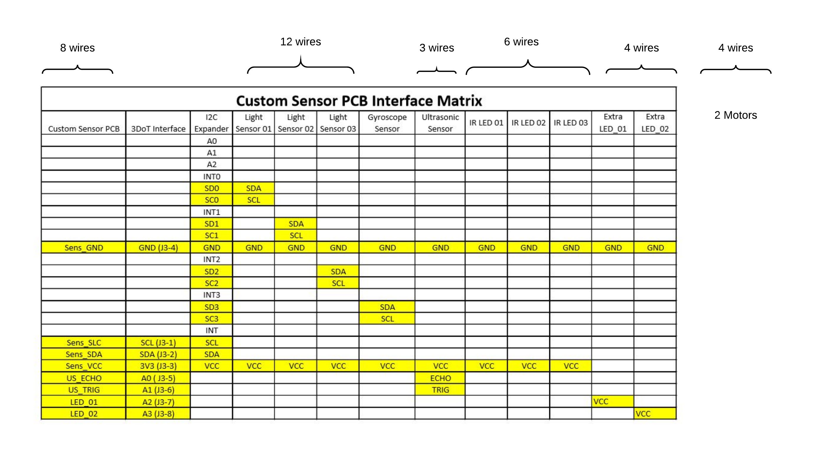
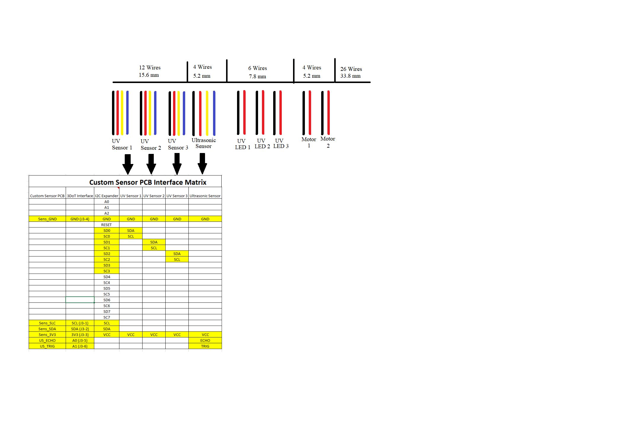
Interface Matrix
Based on customer concerns with the TPS61253A 9-ball 1.2-mm x 1.3-mm WCSP package, we explored other methods to not use a boost converter and further investigate operating all electronics of the robot at the rated 3.6 V from the RCR123A battery. After improving the gear mechanism with the addition of bearings and bushings, we were able to operate the robot at 3.6V while having stable movement with weight attached on top of the robot (simulating the final weight of all devices used for the final robot configuration). Since this change occurred, we no longer will use any connections from J1 and J2 from the 3DoT board. UV LEDs will no longer be used and will be replaced with IR LEDs. Based on customer recommendation instead of using the 8-channel TCA9548A I2C model, we are going to use a 4-channel model: PCA9544A. All peripheral devices will be connected to the Custom Sensor PCB developed by Kris Osuna (Electronics and Control Engineer). The Custom Sensor PCB is connected to J3 of the 3DoT board. Two additional extra LEDs are added to act as eyes of the spider
https://www.arxterra.com/spring-2018-3dot-hexy-interface-matrix/
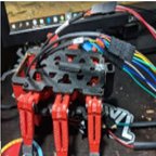
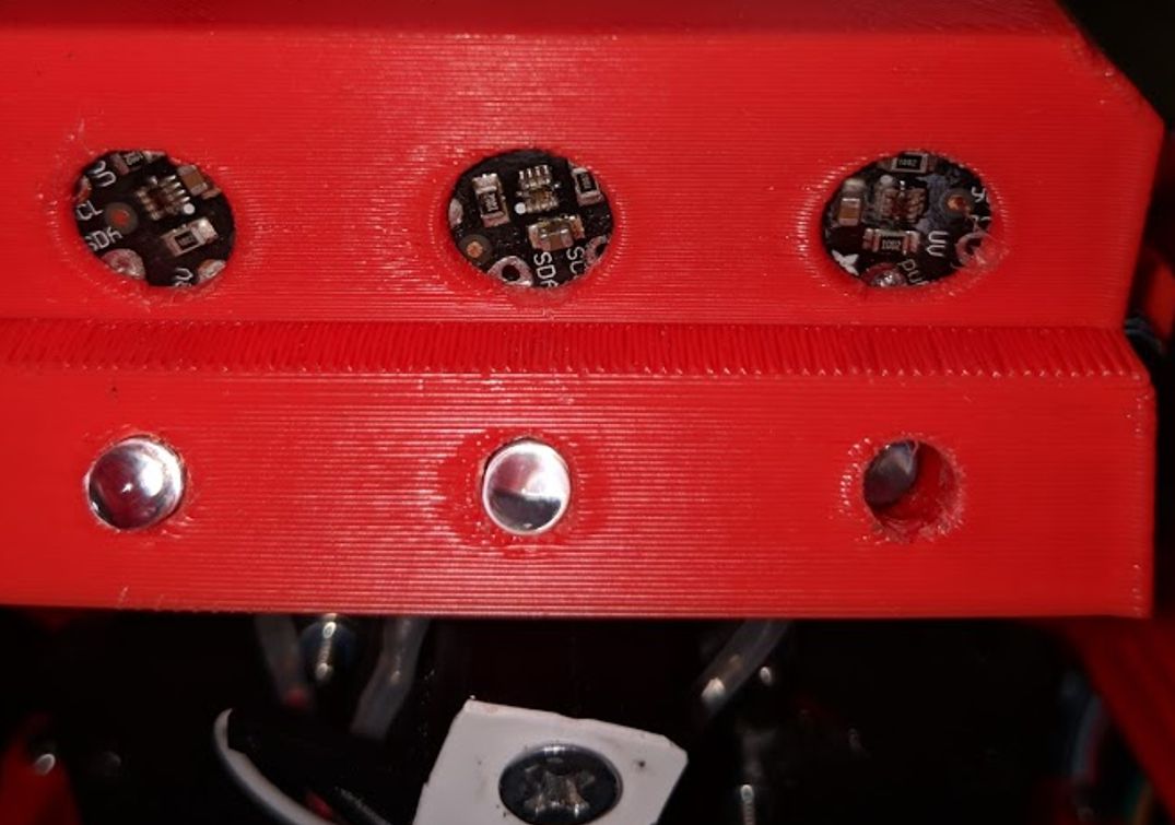
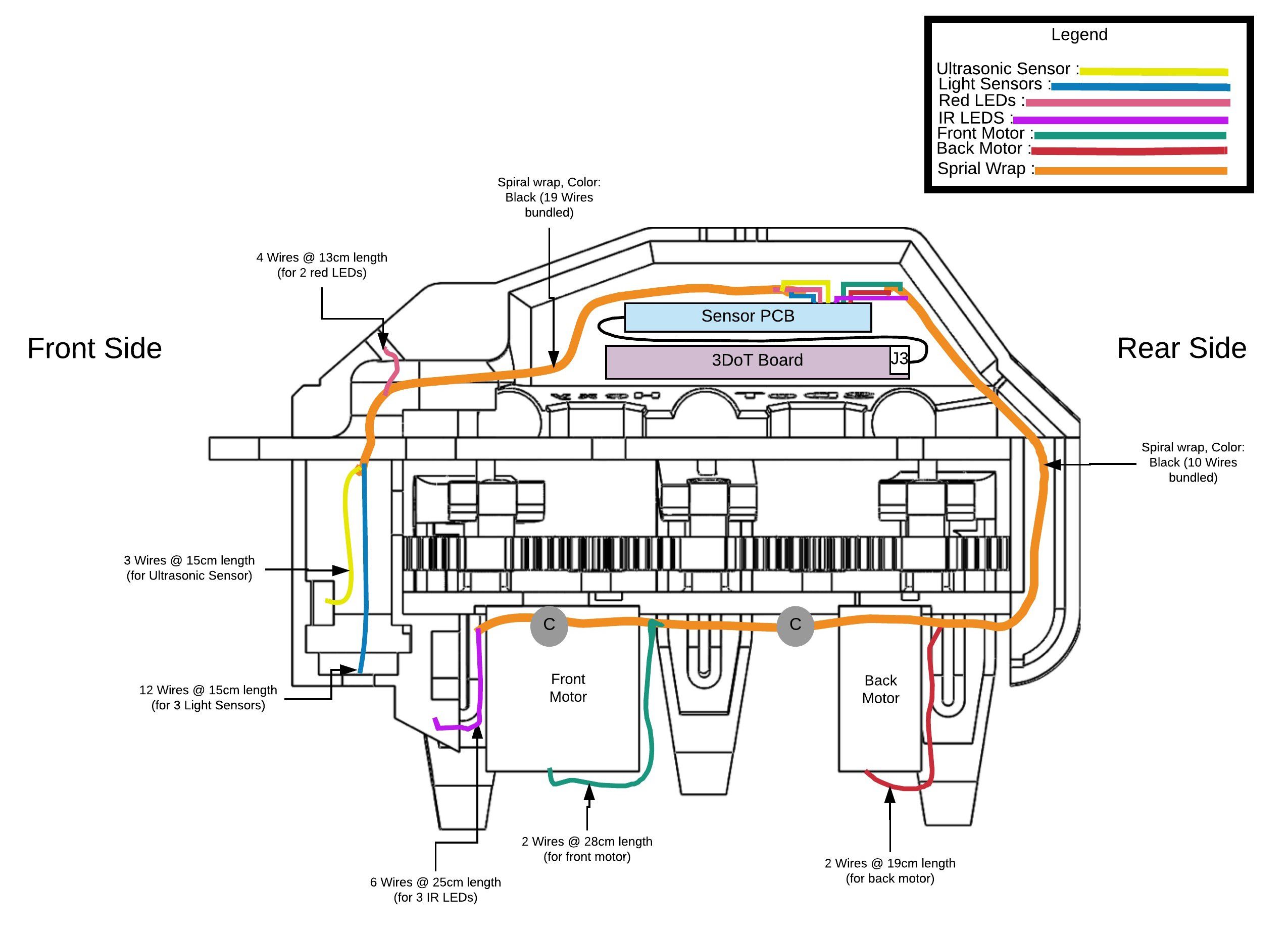
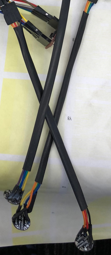
Cable Tree
Based on our design, it did require a lot wires which caused some issues when integrating all of them to their final position/destination. One main problem was with the positioning of the three-light sensors. A recommendation for a design improvement is to integrate the light sensors into the custom sensor PCB and place the PCB at bottom front bracket. The issue that needs to be further looked at is the 30-degree angle needed for the IR LEDs and the positioning so they maintain that angle. Another recommendation is start the design of the robot by first thinking about the wiring route and possibly integrating 3D printing wire assist clips to ease in the final product wiring. Images and wire interfacing are provided in the blog post below.
https://www.arxterra.com/spring-2018-3dot-hexy-system-cable-tree/
Getting 3DoT David Working
Since we planned on basing our design of Spring 2016 3DoT David, the manufacturing and E&C engineers got to fixing, and analyzing the design. Below is a blog post explaining what they learned and planned on improving. https://www.arxterra.com/spring-2018-3dot-hexy-getting-3dot-david-working/
Decision on Movement Mechanism
Having had studied the klann Linkage Mechanism and the Spring 2016 3DoT David Hexbug 2 Mechanism more in depth, we decided that implementing the Hex Bug 2 design was the way to go. Reasoning behind picking this mechanism is provided in the blog post below. https://www.arxterra.com/spring-2018-3dot-hexy-decision-of-movement-mechanism/
Determining Gear Design
We decided that pursuing a 3:1 configuration would be the way to go. This is due mainly to the femur-to-gear joints. Design specifications for our 3:1 cam design is provided in the link below.
https://www.arxterra.com/spring-2018-3dot-hexy-determine-gear-design/
Improving 3DoT David Design
Since we decided to model 3DoT Hexy of Spring 2016’s 3DoT David, Prof. Hill recommended that we get in contact with the owner of 3DoT David to have access to the robot. Luckily, we were able to get in touch with the owner and were permitted to use the robot as a reference. From 3DoT David, we learned a lot about: movement dynamics, overall dimensions, and weakest points in the structural design. From the design we decided to modify: the gear capture system, gear to motor shaft connection, lift mechanism, leg joints, wire management, redesigning the top and bottom plate. https://www.arxterra.com/spring-2018-3dot-hexy-improving-3dot-david-design/
Mission Commands and Control
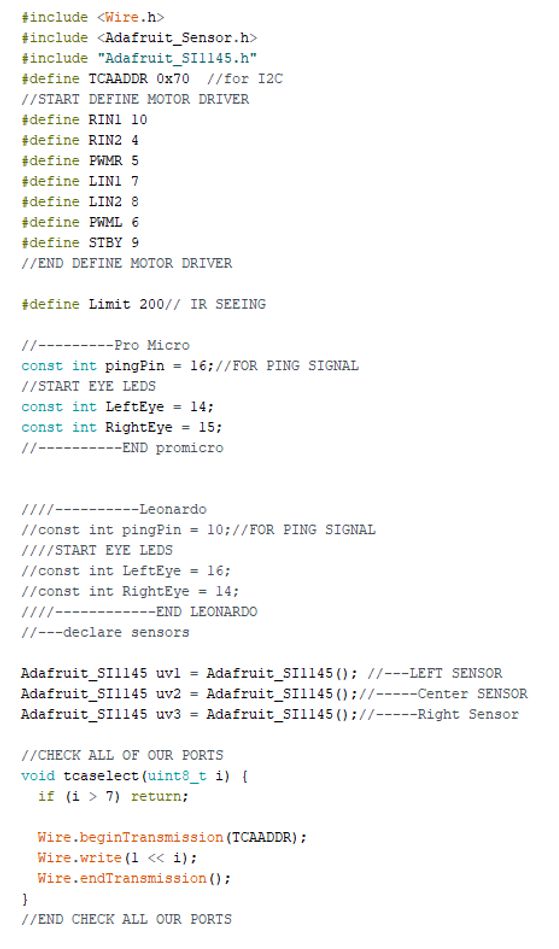
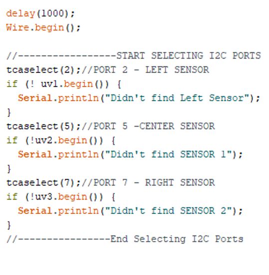
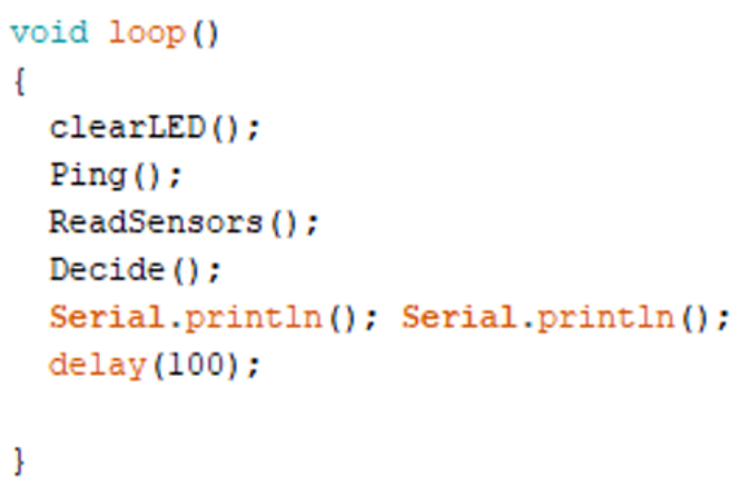
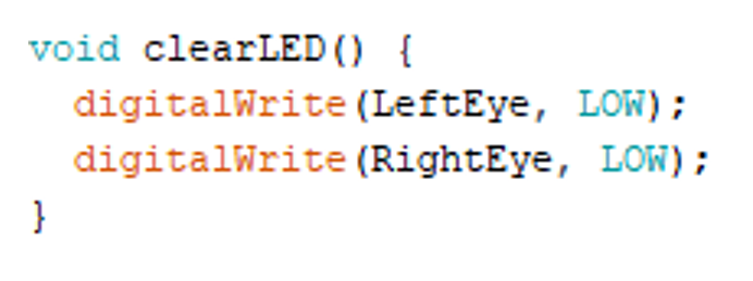
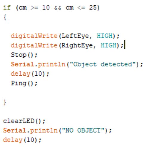
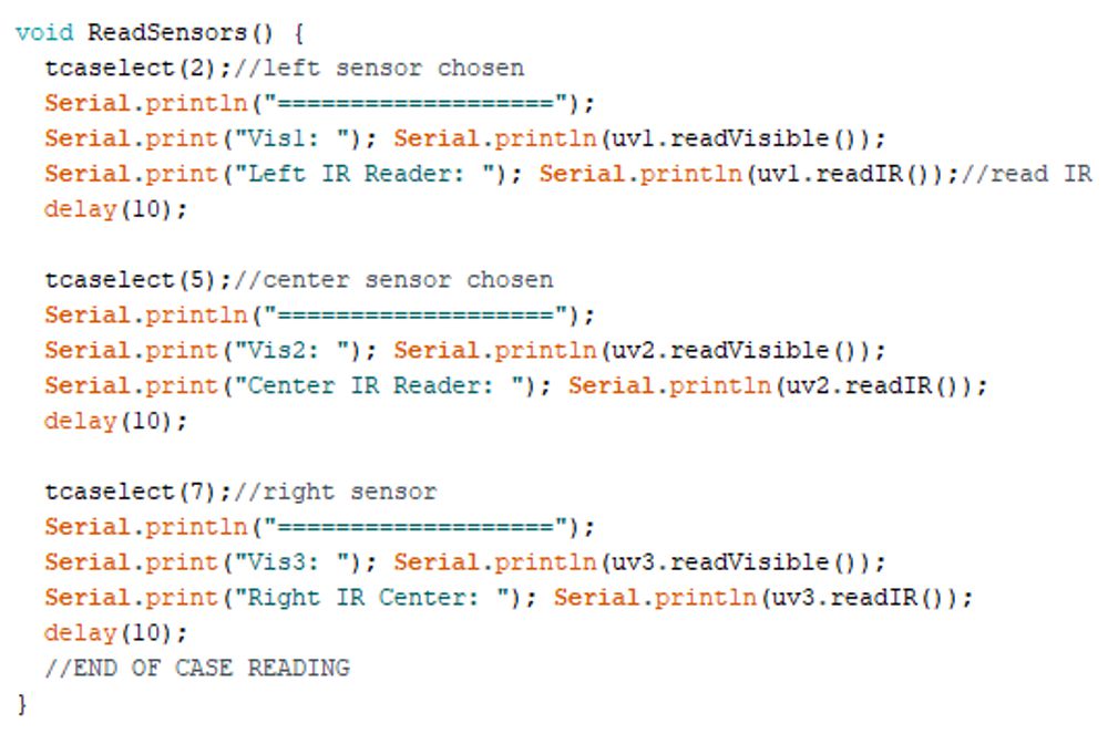
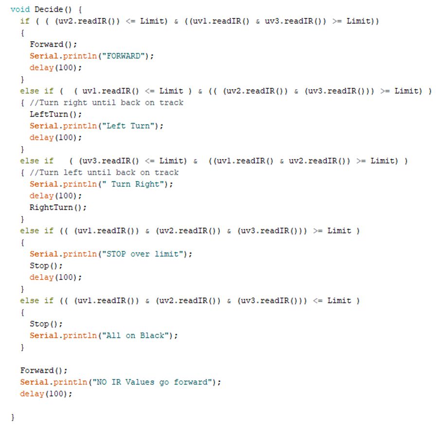
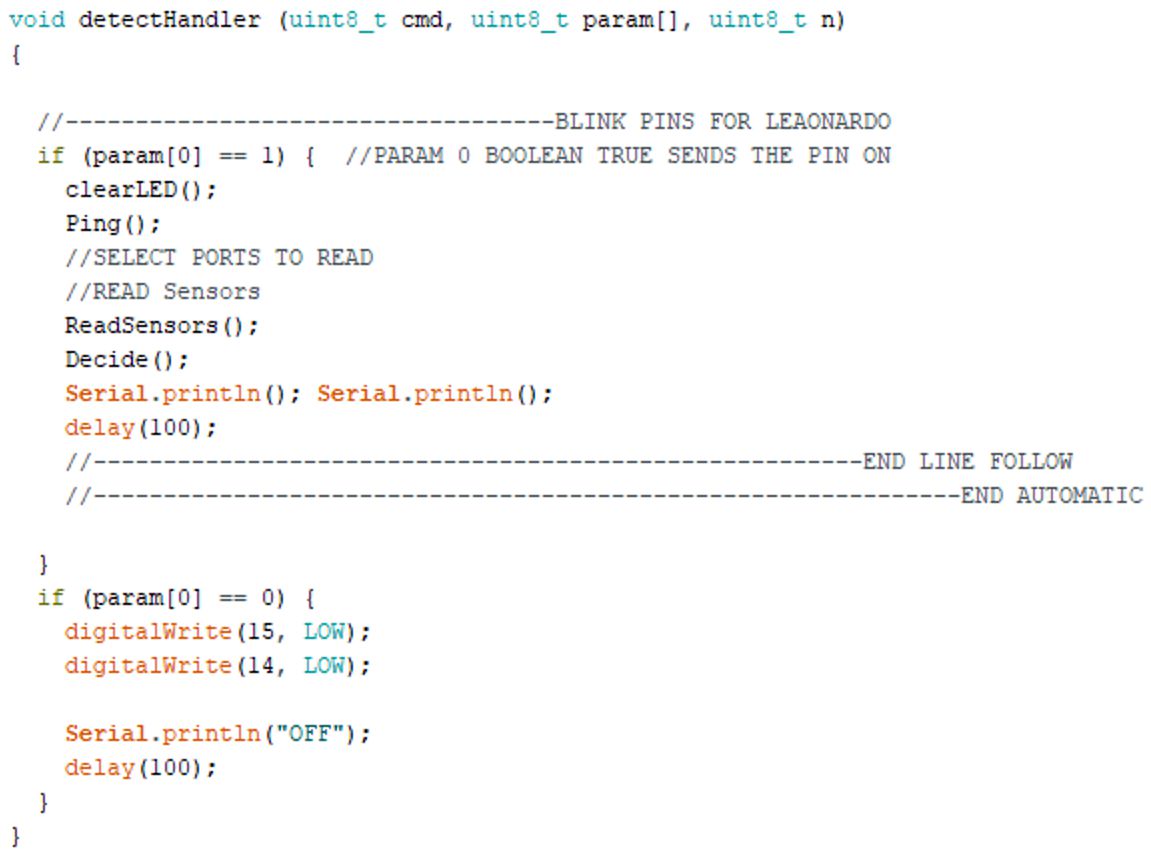
Final Software
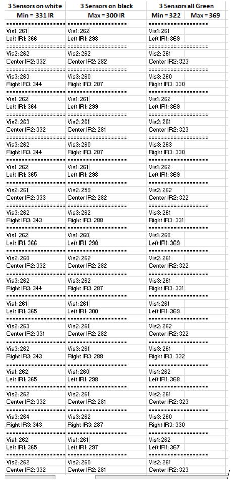
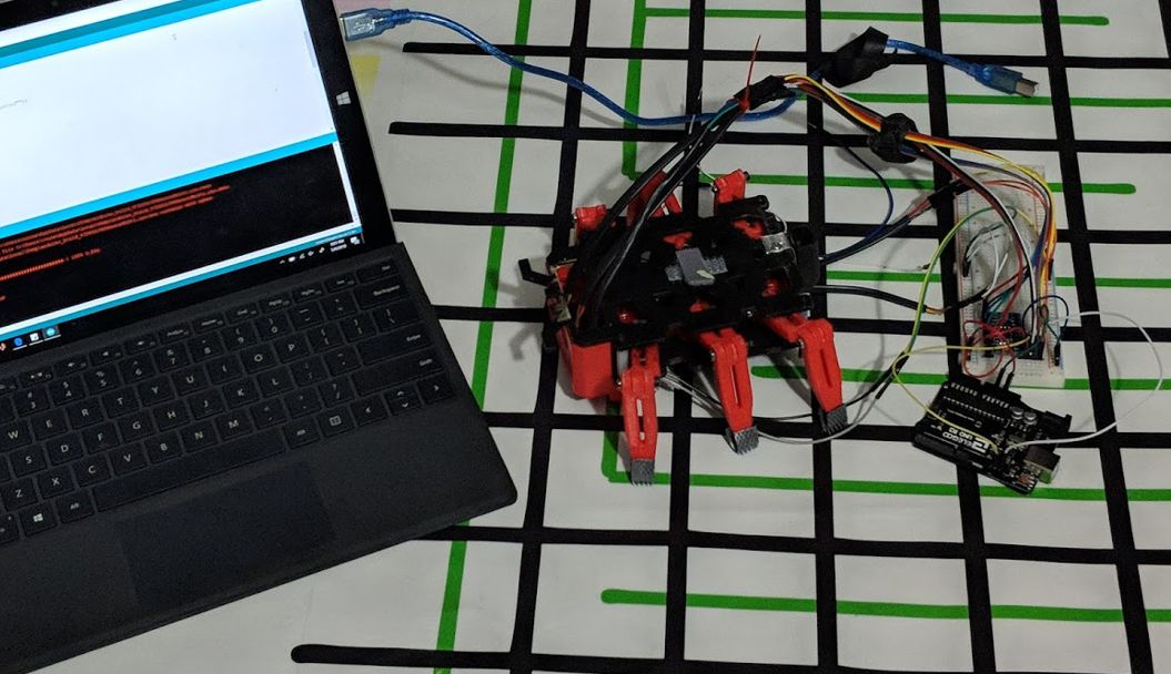
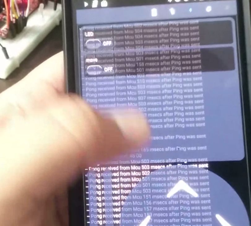
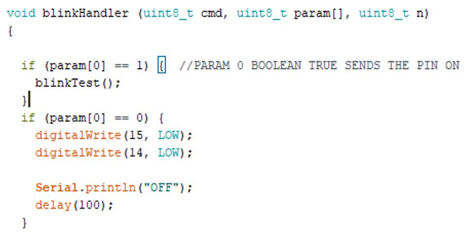
The E&C Engineer was unable to get the line following code to function correctly on the arxterra app. The line following on Arduino only worked ok but due to the sensors not fitting correctly in their spot, consistent values were difficult to obtain. The sensors kept moving positions and angles. The blink custom command shows that the handle is correct and is going through, but Detect command does not work for some reason. Our team did not have a dedicated software team member which lead to extra work on the E&C Engineer. If we had another team member we could have gotten the code working.
https://www.arxterra.com/spring-2018-3dot-hexy-final-arduino-code/
Electronic Design
Fritzing Diagram
We used the open source fritzing software to create a prototype that will show all connections to an Arduino Leonardo. The Leonardo is used because it uses the same processor as the 3DoT board. The Leonardo provides 3.3V to the pins which is less than the 3DoT board provides, so if it works on the Leonardo it will work on the 3DoT board. The prototype will be able to move with motors connected to a dual motor driver to control the motors. Three UV sensors will be connected with three UV LEDs. The UV sensors and LEDs will help the robot navigate the maze. An I2C multiplier for the serial data is needed. An ultrasonic sensor is needed with two digital pins. The ultrasonic sensor will detect other obstacles. We were able to use an ultrasonic distance sensor with only one digital pin.
https://www.arxterra.com/spring-2018-3dot-hexy-prototype-fritzing-diagram/
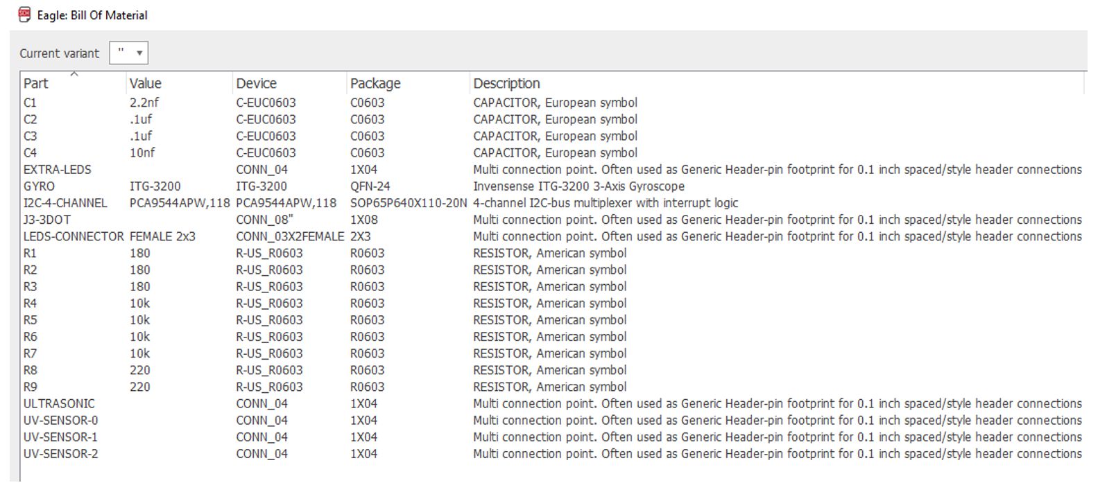
PCB Schematics
The PCB schematics included in the blog post below are for the custom sensor shield designed by the E&C engineer. The schematic must contain these parts: 1-to-4 I2C multiplex, connection to UV sensors, connection to LEDs connection to ground and power and connection to the ultrasonic distance sensor. The UV sensors, ultrasonic sensor, LEDs and booster are not going to be directly to the schematic. https://www.arxterra.com/spring-2018-3dot-hexy-spiderbot-schematic/
PCB Layout
Two PCBs were designed by the E&C engineer: a sensor shield and a booster shield. The booster shield was discarded for a variety of reasons. 3DoT Hexy has been improved and can move with the load at 3.7V. We will no longer be using the UV LEDs at 5V instead we will be using IR LEDs at 3.3V. E&C suggests learning Eagle CAD and starting this process as early as possible due to the fact that the PCB design process undergoes multiple reviews before getting the green flag to print.
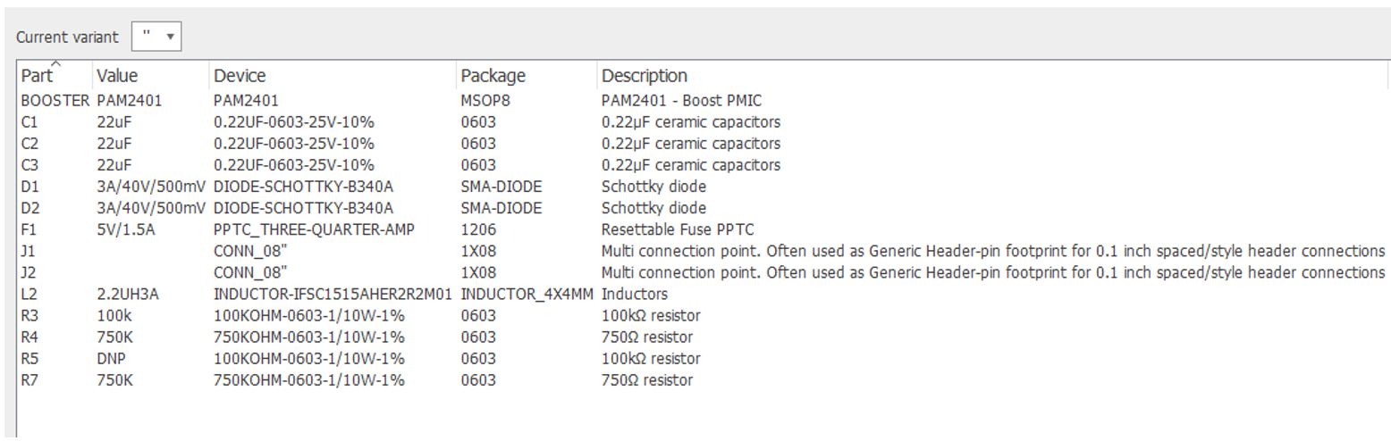
Booster Shield Layout
https://www.arxterra.com/spring-2018-3dot-hexy-booster-shield-layout/
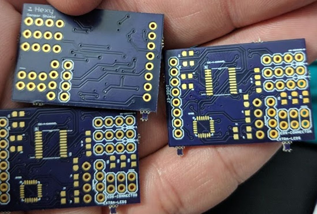
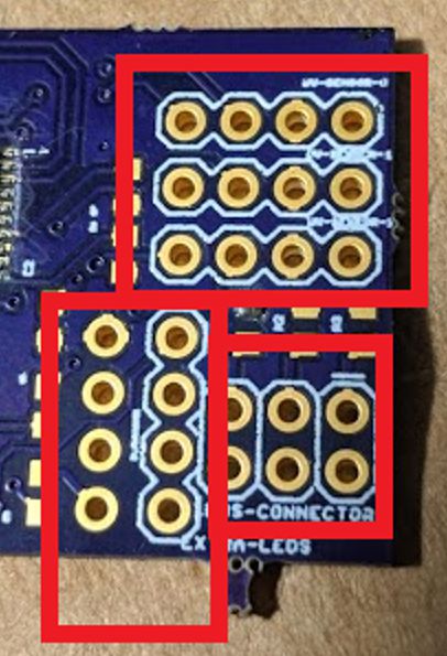
Sensor Shield Layout
https://www.arxterra.com/spring-2018-3dot-hexy-sensor-shield-layout/
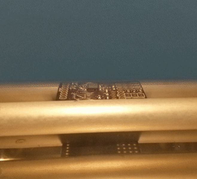
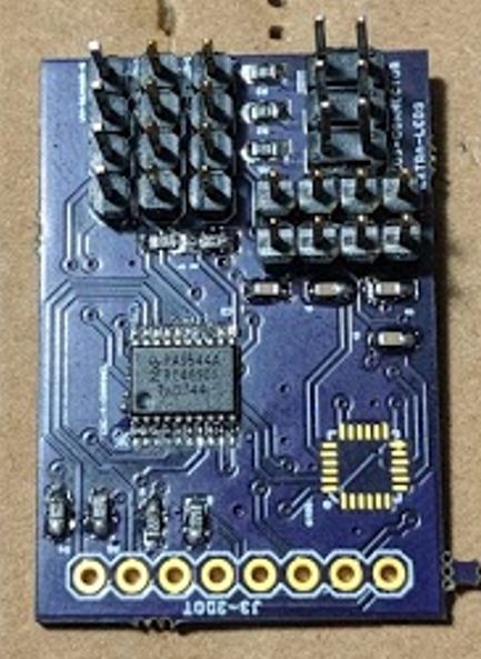
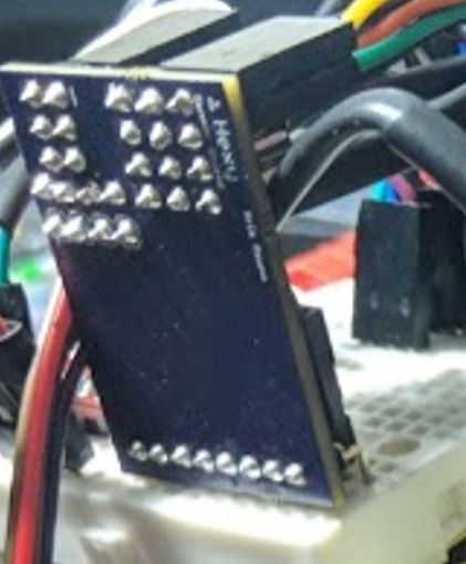
Custom PCB Assembly
https://www.arxterra.com/spring-2018-3dot-hexy-custom-pcb-assembly/
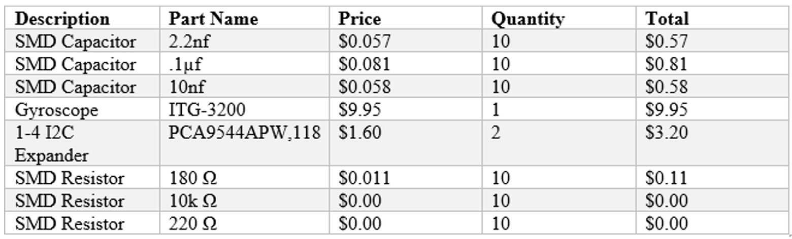
Bill of Materials (BOM) Report
This post shows all the parts needed to create the custom shields for the 3DoT. It also includes the cost of items that will not go on the shield but is needed to make 3DoT Hexy work correctly.
https://www.arxterra.com/spring-2018-3dot-hexy-electronic-component-bom-and-order/
Hardware Design
Blueprints/Mechanical Sketches
The blueprints show the dimensions of all parts designed in solidworks. These should aid the manufacturing engineer in designing 3DoT Hexy if the solidworks files are not available.
https://www.arxterra.com/spring-2018-3dot-hexy-mechanical-drawings/
3D Models
The 3D models give detailed explanations of why things look the way they are. We went through 4 revisions of our design before producing a design we were satisfied with.
https://www.arxterra.com/spring-2018-3dot-hexy-3d-model/
Prototype Part Adjustment/Modifications
This post gives a quick run through of all the things we modified and learned from creating the prototype. For the most part it would play to the teams advantage if the manufacturing engineer has to his disposal tools such pliers, different types of screwdrivers, rotary power tools, drills, power saws, etc.
https://www.arxterra.com/spring-2018-3dot-hexy-prototype-part-adjustments-modifications/
Assembly
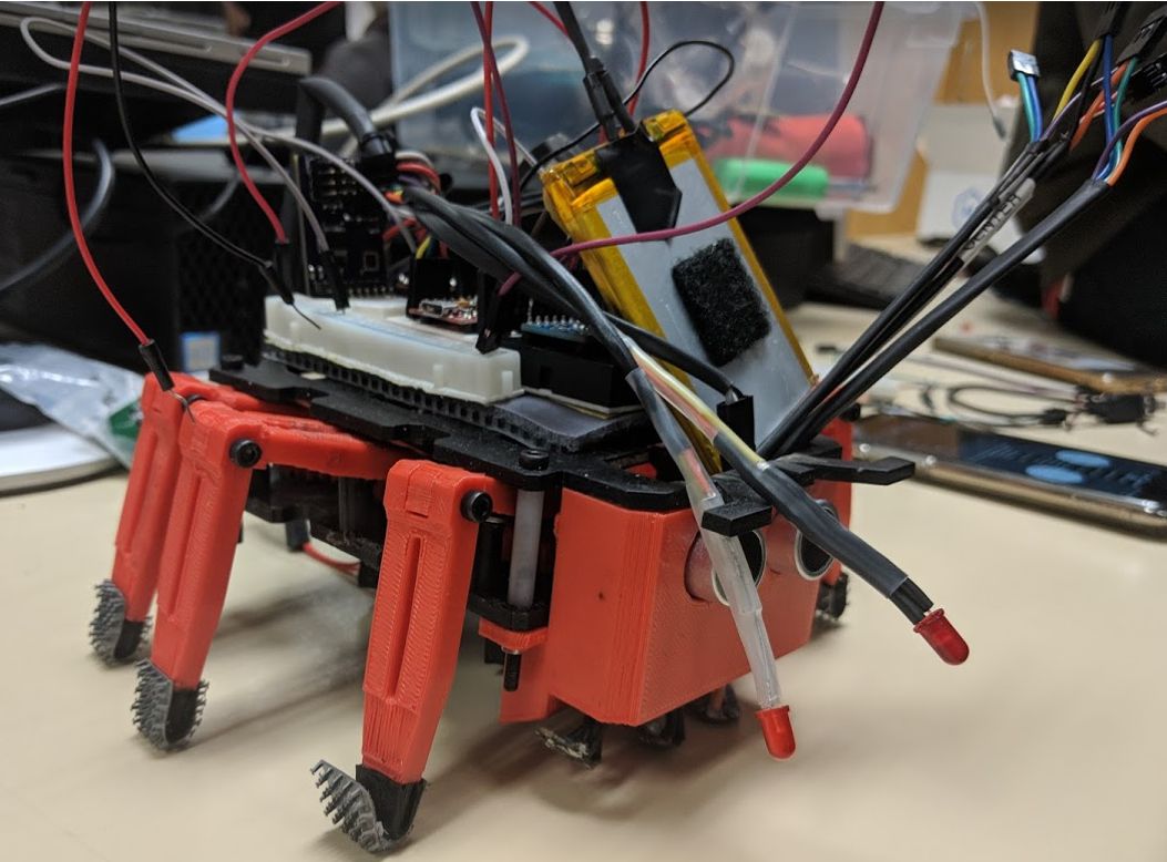
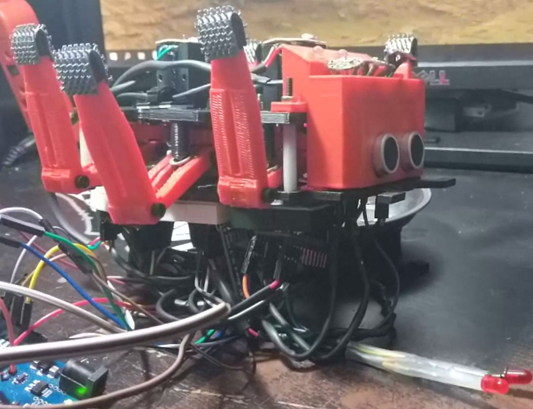
The purpose of this blog post is to demonstrate how all parts designed in Solidworks were put together along with other outsourced materials. We will be assembling two models of our robot: the prototype and the final model.
https://www.arxterra.com/spring-2018-3dot-hexy-assembly-prototype-final/
Project Status
Resource Report
This blog post covers 3DoT Hexy’s Resource Report which include cost, power and mass.Values for the battery and 3DoT board were initially estimated based on the final blog post of 3DoT David. Values for each component or device are updated as the project is further developed
https://www.arxterra.com/spring-2018-3dot-hexy-resource-report-cost-power-mass/
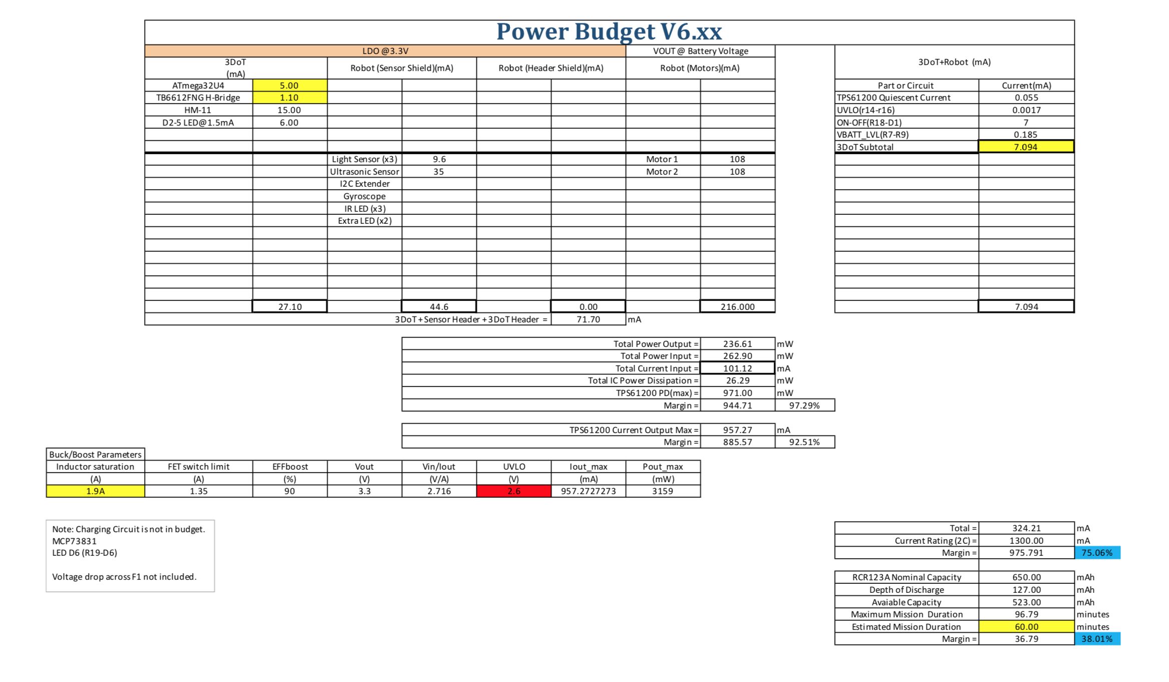
Updated power budget can be found by clicking the link below.
https://www.arxterra.com/spring-2018-3dot-hexy-power-budget/
3D Print Times
Print time quotes were obtained from two sources: Ridwan and Long Beach Makers. Parts for prototyping were printed with a .3 mm layer height for quick production.
https://www.arxterra.com/spring-2018-3dot-hexy-3d-print-times/
Product Breakdown
This document follows the Work Breakdown Schedule (WBS) developed by Eduardo De La Cruz (Project Manager and Manufacturing Engineer). This PBS is split into five sections to outline the major components of 3DoT Hexy. The five sections are electronic hardware, software, movement, manufacturing, and power
https://www.arxterra.com/spring-2018-3dot-hexy-product-breakdown-schedule/
Work Breakdown Structure
The diagram is broken down into task each division engineer will be responsible for in the production of the final product. These assignments are based of the task matrix we developed as a class. Engineers can use this diagram as a reference for what they need to do. https://www.arxterra.com/spring-2018-3dot-hexy-work-breakdown-structure/
Project Schedule
The project schedule was generated using excel’s Gantt project planner. The project schedule mirrors the time frames and due dates established in the task matrix. The goal is to provide a visual reference of how far or close one is from reaching their deadlines for a given task. A majority of our task were completed past established due dates. Despite this, we were able to complete the majority of our task. A burndown is included that shows how close we were to completing all our task.
https://www.arxterra.com/spring-2018-3dot-hexy-project-planning-and-scheduling/
Final System Integration and Test
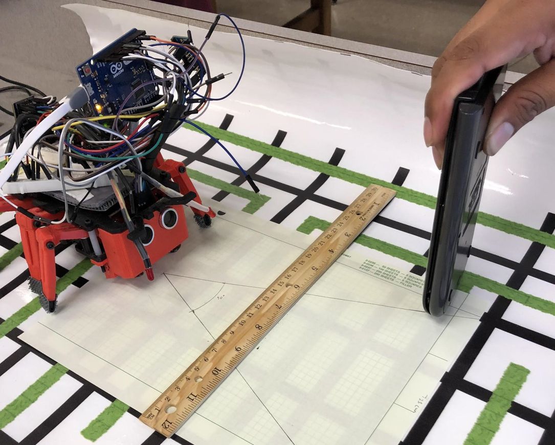
Most of the tests were conducted prior do the day of the final (05/15). Tests performed include ultrasonic ranges, light sensor value readings, and arxrobot communication to the pro micro board. Assembly and disassembly were performed on the day of the final.
https://www.arxterra.com/spring-2018-3dot-hexy-final-system-integration-and-test/
Preliminary Design Review (PDR)
The preliminary document is a progress report made half way into the semester that covers everything we have done. As of the preliminary design, we had not yet created a prototype of our design. It is very important that the team is able to get a prototype ready by the PDR day in order to get feedback by the professor.
https://www.arxterra.com/spring-2018-3dot-hexy-preliminary-design-review/
Conclusion
There were still a lot of things that needed to be done by manufacturing and E&C to make the final product perfect. For the most part we were able to control the spider as an RC toy. More time needed to be invested in autonomous control in order for the spider to have been able to navigated through the maze autonomously. Things that the next generation can improve on are:
1. Substituting the brass bushings used to pinch the gears for a more stronger material that doesn’t warp when tightened.
2. Exploring ways to reduce the play in the legs (wiggle) will make the design more sturdy.
3. Reducing the scale of the robot, in order for it to fit in a maze room
4. Method of hedge/line detection for autonomous navigation. For the most part we spend an extensive amount of time pursuing UV line detection only to end up with IR detection. It would be interesting to explore alternative methods of hedge/line detection that don’t involve IR.
5. Wire Management. As explained by the professor it is best to design a project based on the wire positioning. MST and Manufacturing should get together and agree on a design that looks good and keeps in mind how all wires will be routed.
6. Removing the driving gear and just connecting the motors to either one of the two gears that connect to the 30T gears will achieve the same results. This will eliminate the need of the additional gears.
Lessons Learned
For the most part we learned a lot about what to expect from EE400D. Below are some helpful tips to help the next generation get a head start.
https://www.arxterra.com/spring-2018-3dot-hexy-lessons-learned/
Resources
PDR Power Point
UPDATED-3DoT Hexy_ Preliminary Design Review (1)
Project Schedule and Burndown
Verification and Validation Documents
Master-Verification List-and-Test-Procedures_3DoT_Hexy_5_15_18 Verification_Test_3DoT_Hexy_Spring2018_Final
Verification_Test_3DoT_Hexy_Spring2018_Final
Solidworks files
Frtizing Diagram
Eagle CAD files
Arduino Code
BOM
Sample Waiver
Request for a Waiver of Program Requirement
Project Video
https://www.youtube.com/watch?v=z3S46hI10LI&t=1s


