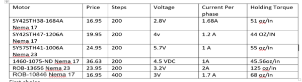
Objective: Currently, we will be using our own Arduino Leonardo while the Thursday Pathfinder group (referred to as the chassis group) will also have their own Arduino Leonardo. The solar panels Arduino and chassis Arduino will communicate using I2C interface on Arduino. In order to ensure the concept is understood completely, the following experiment was done with an Arduino Mega and Arduino Uno, where the Mega was used as the Master and the Uno as the slave.
The following were the components used for the experiment:
Arduino Uno
Arduino Mega
LED
Resistor
Breadboard
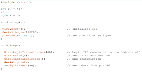
Figure 1: Code to set up Mega as master
The code in Figure 1 was used to set up the Arduino Mega as the master. The serial monitor was used to debug the system; however it can be removed without affecting the code. Wire.Begin starts the communication using the I2C and address must be inputted. Wire, write is then used to send data to the Arduino. To end the communication using the I2C, Wire.endtransmission needs to be used.
Figure 2: Code to set up Uno as slave
The code in Figure 2 was used to set the Arduino Uno as the slave. The key difference is that the Arduino is given an address by writing wire.begin followed with address. The address given to the Arduino is 400 because of the class but any number could have been used. In addition, a subroutine has to be made so that when data is sent, the Arduino goes to the function and does something with the data received. Note that the function called cocoon was created but any other function can be used.
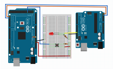
Figure 3 shows the Fritzing Diagram showing how the circuit is configured.
Figure 3: Fritzing Diagram
Figure 4: Visual Results of Experiment
Figure 4 shows the results of our experiment, i.e. our code working: every time the button is pressed, the Arduino Mega reads the value and sends the value to the Arduino Uno. As a result, pin 13 is set to high whenever the value received is one. Since we do not have both projects done yet, I am using the button as the Arxterra signal that will tell Arduino mega to cocoon. A LED on means subroutine cocoon is active in the Arduino Uno and inactive if the LED is off.
This experiment verifies that communication between two Arduinos is possible.
https://www.arxterra.com/wp-content/uploads/2016/11/Untitled4.png263430Inna Echual/wp-content/uploads/2013/04/Arxterra-Logo-340x156.pngInna Echual2016-11-10 22:19:432016-12-06 16:30:04Fall 2016 Solar Panels: I2C Communication Experiment
Objective: The following experiments were used to determine if a DC motor can be used in place of a stepper motor by configuring it to be as precise as a stepper motor. Using DC motors will be beneficial to our design as we are trying to provide power.
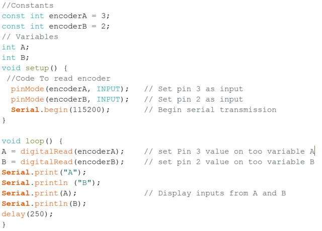
In the first experiment, the Arduino Uno was connected to an encoder—the signals the encoder provided was then analyzed as the shaft turned.
Parts Used:
Motor shield V2.0
DC motor with encoder
Push button
Breadboard
12V Power Supply
Figure 1: Breadboard Configuration
The following code was used:
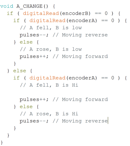
By taking a look at the serial motor I notice I was receiving zeros and once. The four different patterns received were 00, 01, 10, and 11 (this pattern repeated). Figure 1 explains the output of the serial motor where each output is offset by 90 degrees. The reason we have two outputs from encoder is to determine the direction of the motor. By analyzing the figure below, we can come up with a true table for direction.
Figure 1: Output of Serial Motor
If A goes from 0 to 1
B=1
Reverse
B=0
Forward
If A goes from 1 to 0
B=1
Forward
B=0
Reverse
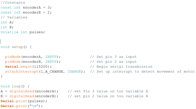
In order to track a pulse each time it occurs, we need to have an interrupt in our code so that we do not miss it. Every time a pulse occurs means that the motor has moved certain degrees. To find the ratio between pulses and degrees, I will measure the number of pulses for 1 rotation using the following code. Without adding power to the motor all that is required is to manually rotate the shaft 360 degrees.
A value of 2071 is what I tested for a full rotation. I divided 2071 by 360 and got 5.75. About 6 pulses will rotate the motor 1 degree and this concept is what I will used to control the motor with precision. If I will I like to move 2 degrees to the left or 2 degrees to the right, then 12 pulses are needed. Once 12 pulses have been received then the motor needs to stop. The next experiment will focus on being able to stop the motor after a full circle.
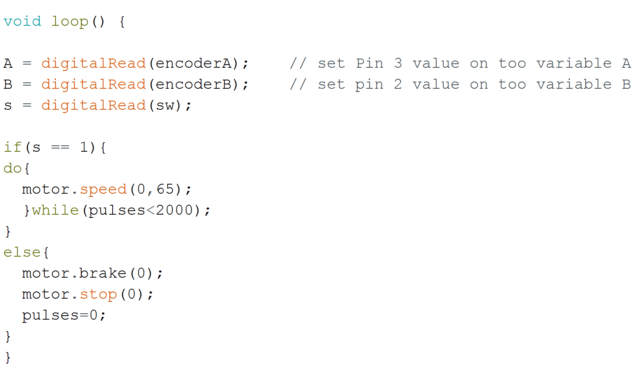
The following code was used to control the motor. A switch button is used to let the Arduino know when it should rotate. Pressing the button causes the motor to rotates and stops once 2040 pulse have been reach. Due to the fact that the motor is too fast, a perfect rotation cannot be done. A motor with slower rpm but strong torque could potentially respond better. In addition, a gear motor will be more acceptable because we can relate a 360 to 1 gear ratio as 1 degree for every rotation. In the solar panel design, a maximum gear ratio of 50 to 1 is what we can attain. A DC motor could not be used in our project. A stepper motor has been determined as the only option available due to time and gear ratio availability.
https://www.arxterra.com/wp-content/uploads/2016/11/400d.jpg480640Inna Echual/wp-content/uploads/2013/04/Arxterra-Logo-340x156.pngInna Echual2016-11-09 22:17:202016-11-09 22:36:02Fall 2016 Solar Panels: DC Motor with Encoder Experiment
The team received the PDR debrief from meeting with the customer and the president. A concern of theirs was that our mission profile presented during the PDR (1) was not updated as the Chassis group in the Thursday class had changed their course to an area with a stronger WiFi signal and (2) was representative more of the Chassis group’s mission profile instead of ours.
Because of the two reasons, the team then developed a new mission profile which will clarify the confusion present in the current one.
Previous Mission Profile
The project will be demonstrated by charging the pathfinder’s battery using solar panels in order to completing the course defined by the Spring 2016 AdBot rover, as shown in Figure 1. This course is on the California State University, Long Beach campus, specifically in front of the University Student Union building and will be conducted at night for better operation of the LiDAR sensor.
Figure 1: Spring 2016 AdBot Rover Route
Updated Mission Profile
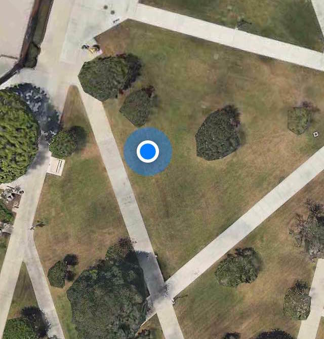
The project will be demonstrated by parking the Pathfinder in the Central Quad on California State University, Long Beach located at 33°46’40.7″N 118°06’48.9″W. In addition to the location near the defined travel course, the parking spot was chosen as it had low traffic and free of shading. The parking spot is indicated in Figure 2.
Edited and Approved By Inna Echual (Project Manager)
Folding Mechanisms Considered
Objective: One of the most important components of our project is to define the folding mechanism that will allow us to achieve the cocooning requirement. This study will showcase the mechanisms we considered and which of the ones research was chosen.
Rack and Pinion
Video 1: Rack and Pinion Folding Mechanism
This idea was brought up through a YouTube search on “folding mechanisms,” resulting in the rack and pinion method in the video above. The folding is accomplished by sliding a rack back and forth and spinning a spur gear placed at the hinges of the panels. This configuration was created to fold t-shirts but I found this video to be very helpful.
For doing this method, the rack would have to be suspended from underneath the panel because doing a two-layered panel configuration like the video would be unfeasible as it would result in more materials, adding cost and weight. Taking those factors into account, it was additionally determined that is method is not the best for folding our panels since having the rack be suspended underneath could prevent the side panels from going -15° (for example) when the panels articulate to track the sun.
However, this video inspired us to consider attaching a gear to the pin of a hinge and to consider a gearing mechanism to do the folding of the panels.
Linear Actuator
Video 2: Linear Actuator Folding Mechanism
This method of using a linear actuator was both found by doing the same YouTube search and as suggested by Professor Hill. Though the linear actuator would provide enough force to push open our panels despite its weight, we had many concerns:
An obvious placement of the actuator would be on the stationary front side panel and on the side closest to the base (see Figure 1). This placement would cause two problems: (a) we would be losing valuable real estate for putting our solar cells, space that we need to achieve power generation for charging the battery. And (b) putting the actuator on the top will prevent our back side panel from completely closing onto the back front panel, which also brings up the problem when folding the two onto the base for the cocooning.
To fix the problems brought up in (1) above, we considered placing two pads on the side of the front panel furthest from the base panel (see Figure 2). Our problem with this placement is that we assumed putting pads there would dissatisfy with the Level 1 Requirement of having the panels be identical to that of the Opportunity and Spirit rovers. The placement there would also be not ideal as since the actuator is on the other side of the side panel, it could interfere with the rover’s overall center of mass.
We also considered placing the actuator underneath the panels but we had difficult time finding a mechanical configuration to encompass the 0° to 180° range of the panel folding.
Therefore, we determined that this method was not the best and we continued to research further on folding mechanisms.
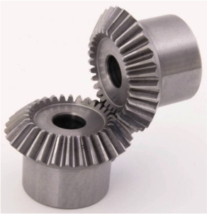
Bevel Gear
Figure 3: Bevel Gear
Through we are not considering rack and pinion method for folding, we were inspired by the gear to incorporate a bevel gear into the mechanism to lift the panels into position. One bevel gear would be fixed to a rod extending from piano hinge and that pin of the hinge will be welded to one side of the hinge on the panel that needs to be lifted.
The main concern is the panel could not be kept at a specified angle and the motors would have to be constantly turned on to hold the panel at that angle. After the Iterative design process and additional research, the worm gear was considered for its self-locking feature.
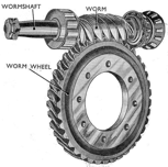
Worm Gear
Figure 4: Worm Gear
The worm gears are considered because of power transfer due to the effectiveness of the two gears meshing. One appealing feature is that they are self-locking, meaning that the gear cannot drive the worm. For example, when the weight of the panels exerts torque, the motor is not affected; if the panels are going from 90° to 180° there won’t be load exerting torque on the stepper motor. Another feature is that they occupy less space which would declutter the design and reduce overall mass.
The most important advantage is that they are known for being used for speed reduction and increasing torque. This will be extremely helpful when doing a lifting action for our sun articulation.
Mounting the Stepper Motor
A custom bracket shall be designed to allow to mount the stepper motor low to the ground.
Torque
Take the right back panel for example:
Weight of panel on SolidWorks using 6061-T6 Aluminum = 165 grams
Distance
For safe measure a weight of 250 grams will be used.
So, a motor with a torque of 23 oz.in or higher will in theory be able to lift the right pack panel.
Gear Ratio
As stated earlier, one of the advantages of worm gear is having higher gear ratios. For this example, a 30:1 gear ratio will be examined.
Motor – NEMA 17-size hybrid stepping motor with a torque of 44 oz.in
Motor Torque x gear ratio = torque at the hinge
This is more than enough to be able to lift the panels.
Figure 5: Lever Arm from Axis of Rotation
https://www.arxterra.com/wp-content/uploads/2016/10/worm.png152153Inna Echual/wp-content/uploads/2013/04/Arxterra-Logo-340x156.pngInna Echual2016-10-25 22:21:072016-12-06 16:31:05Fall 2016 Solar Panels: Folding Mechanism Trade-Off Study
Objective: Motors we need to select must be able to hold the panel at different angles with precision with maximum 12 volts and 2 amps to fulfill the sun tracking requirement. In order to do this, a minimum torque of 50 oz/in is required based on our calculations.
Stepper Motor:
Need to consider the positioning resolution because the number of steps per revolution range from 4 to 400.
Note: Resolution is expressed in degrees. Example- 1.8⁰ is 1.8360= 200 step/rev motor
Higher resolution torque effects the speed and torque by decreasing both as resolution increase
Gearing can help to increase resolution without having to loose torque
In addition, torque can be increased, but the tradeoff will be speed
Pros
Precise positioning
Low Speed Torque
Cons
Low Efficiency- draw the most current when not doing any work
Less Torque at high speed
No feedback- Limit switches or detectors typically required for safety and establishing a reference position
Require a stepper controller to energize
Cost more
Four inputs
DC Motor:
Pros
Cheap
Efficient
Can be controlled using an H-Bridge circuit
Only need two inputs
Cons
Can’t be used for precision
Noise is introduced if not brushless
Brushless DC motors- require a separate controller, ESC
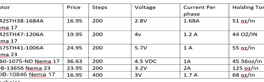
Based on the two key differences on these two motors, we concluded that we will need to use 2 stepper motors to control the sun tracking on the solar panels. Precision is needed and the stepper motor is the only motor that can be controlled to fulfill that precision requirement. In addition, a constant-holding torque is required to hold the panels and the stepper motors are able to provide this. Since the other panels do not require any precision or holding torque, DC motors are more acceptable to be used than stepper motors. The following table shown in Figure 1 will show the motors that I compared and based on my needs I picked one of the 6.
Figure 1: Stepper Motor Comparisons
Final Decision:
The final decision for making the sun tracking possible are the two stepper motors SY57STH41-1006A. They are my choice because it draws only 1 amp and has a holding torque of 55 oz/in, which is required to articulate the panels efficiently.
https://www.arxterra.com/wp-content/uploads/2016/10/Untitled2-e1476808741879.png163600Inna Echual/wp-content/uploads/2013/04/Arxterra-Logo-340x156.pngInna Echual2016-10-18 16:59:272016-12-06 16:32:47Fall 2016 Solar Panels: Motor Trade-Off Study
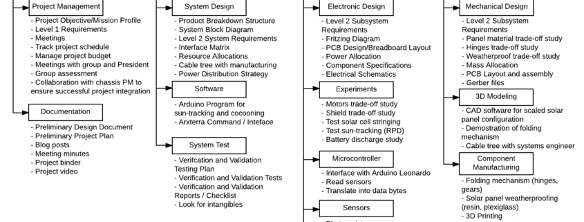
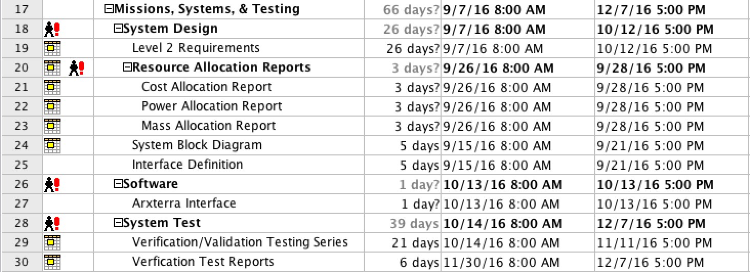
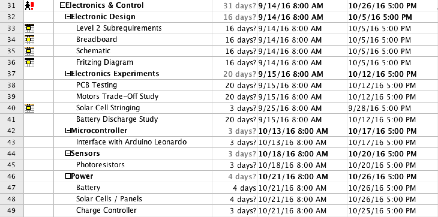
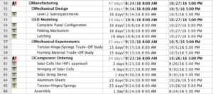
The Work Breakdown Structure shown in Figure 1 demonstrates the work needed to complete the solar panel component of the Pathfinder project. The work branches into the four divisions (including project management) and the work/unique tasks underneath associated with each division.
Project Schedule
By Inna Echual (Project Manager)
Top Level Schedule
Figure 2: Top-Level Schedule
The top-level schedule shown in Figure 2 follows the blocks shown in the work breakdown structure. The major project deadlines are shown under the tasks of the project manager while each division’s individual tasks are nested under their respective division.
Currently, the tasks related to completing the folding mechanism (research, trade-off studies, 3D-Modeling, component specification and ordering, etc.) has the longest completion date and is our current critical path. We don’t have a solid choice for the folding mechanism yet so we still have to do further research and more studies to establish a design in order for our design to move forward.
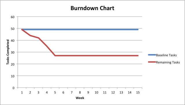
The project Burn Down Chart in Figure 6 demonstrates the work completed so far compared to the total amount of tasks expected to complete the project. The group has completed approximately 30 of the total tasks scheduled for the project. Currently, we are still trying to solidify a design for the folding mechanism so we may fall behind in the upcoming weeks due to research and trade-off studies.
System Resource Allocation Reports
By Stephan Khamis (Mission, Systems, and Testing)
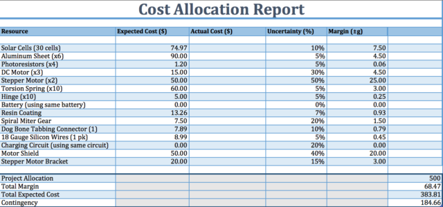
Cost Allocation
Figure 7: Cost Allocation
Our budget that we have set for ourselves is to keep the project under 500 dollars. All of the expected prices listed in Figure 7 are rough approximations or the average price for that type of component as, for instance, we have yet to define the specifications of the stepper motor will be using so its cost is yet to be defined but we have an approximation of its price. We are reusing some of the parts that were on the previous pathfinder, such as the battery and the charging circuit for the battery. Our total expected cost is $383.81 and we have a contingency of $184.66 dollars. We have allowed ourselves a margin of about $70.
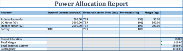
Power Allocation
Figure 8: Power Allocation
The expected power allocations are based on the components we expect to be using. We have not specified our motors yet but we have a range of the current draw based on the models we are leaning towards. Battery specifications were to be provided by the chassis group but they have yet to provide us with their experimental data.
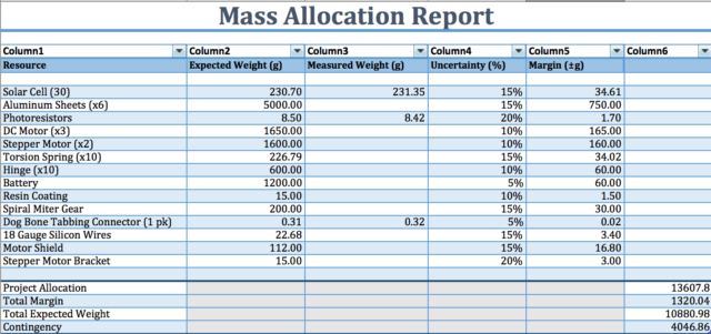
Mass Allocation
Figure 9: Mass Allocation
The mass report in Figure 9 are rough approximations of the mass of each component we expect to be using. We have yet to define specifically the DC motors and stepper motors we will be using so their mass is yet to be determined but we have a general idea. The aluminum sheets will have a honeycomb cutout structure to reduce its mass.
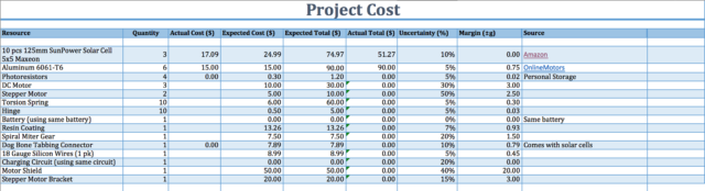
Project Cost Estimate
By Inna Echual (Project Manager)
Figure 10: Project Cost Estimate
From the Cost Allocation Report in Figure 7, the overall projected costs are currently estimated to be $383.81. This price will be subjected to change as the project continues and is by no means a representation of a final product. However, we have already selected the type of solar cells we will be using—which are monocrystalline solar cells that already come with the tabbing connectors, ultimately reducing the cost of the overall project. However, the motors and springs have yet to be defined, which I expect will affect our total cost significantly.