
Spring 2018: Project Power Budget Template
By: Raymundo Lopez-Santiago (Mission, System, and Test)
Verified by: Eduardo De La Cruz (Project Manager and Manufacturing Engineer)
Approved by: Miguel Garcia (Quality Assurance)
Introduction
This blog post covers the 3DoT project power budget. With the design of the version 6.43a of the 3DoT board, the existing power template from last semester needed to be updated. A major change from the last revision to this version is the parameters of the buck/boost converter. The previous revision had the output of the converter at 5V. This current revision has the converter output 3.3V to be used for peripherals needed for each robot project. This revision utilizes the same TPS61200 converter. The battery that will be used is the RCR123A 650mAh, 3.6V Li-Po. The project power budget template version 6.xx has been updated with the help of Professor Hill and Ryan Nguyen.
Project Power Budget (Updated 04/17/18)
Components of the 3DoT can be found in the schematic for the version 6.43a of the 3DoT board. For the schematic, click the following link: 3DoT v 6.43a Schematic.
This version updates the categories defined in the previous version. These categories include the LDO at 3.3V and output from the battery. The LDO incorporates the internal circuitry of the 3DoT board, sensor shield, and header shield. Output from the battery at the rated 3.6V can be used for motors/servos.
The complete power budget spreadsheet can be seen by clicking the following link: 3DoT Project Power Budget Template.
The user can input valued for peripherals used in the correct section. Any sensors should be added to the sensor shield or header section. Motors should be added in the Vout section. See Fig. 2 for clarification. Values inserted for current draw should ones from measurement but values from datasheets will be a good start.
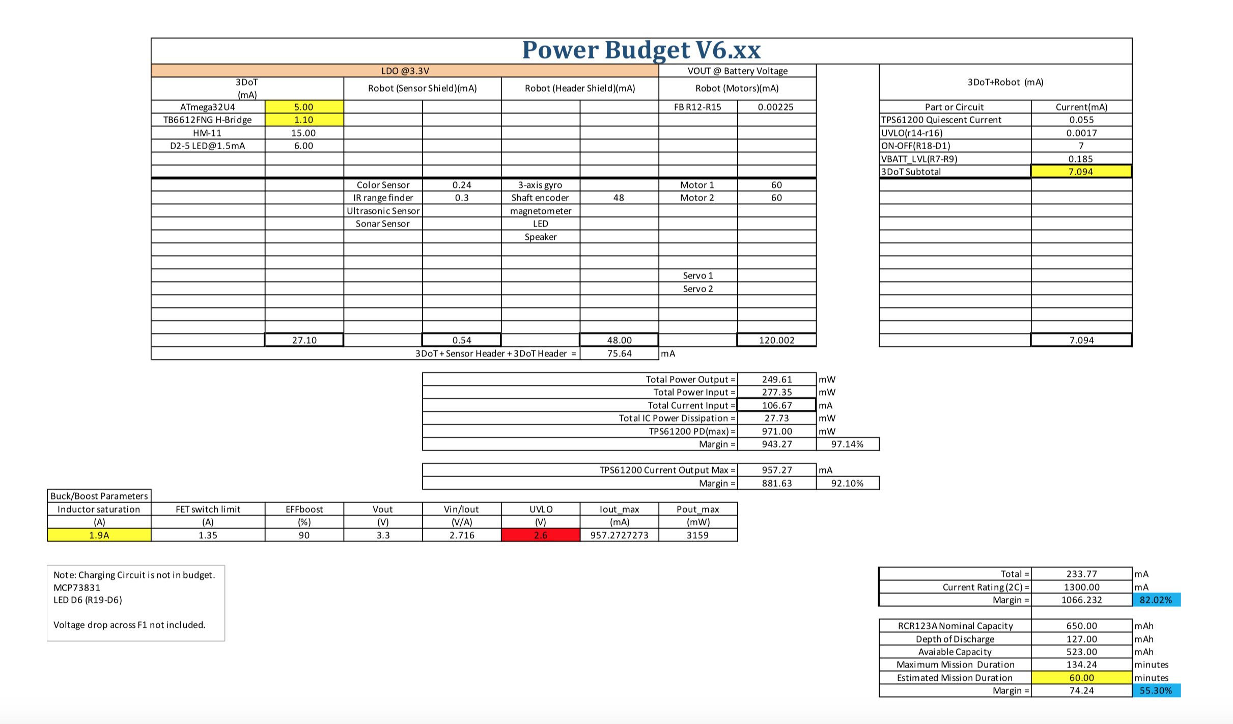 Fig. 1: Spring 2018 3DoT Project Power Budget
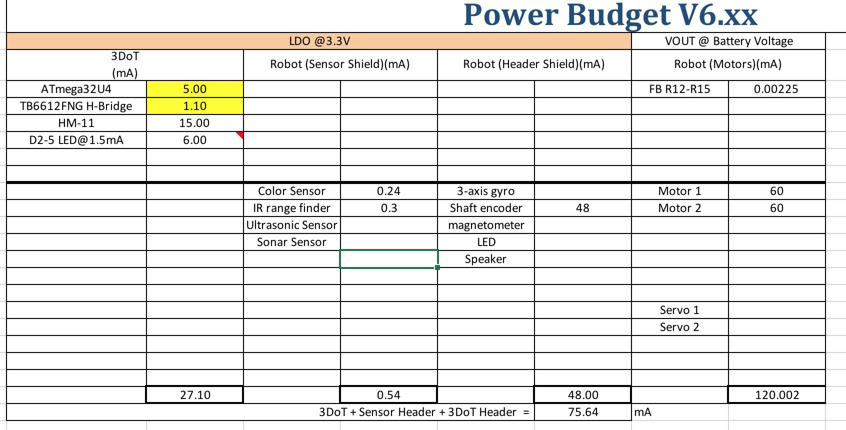
Fig. 2: LDO @3.3V and Vout @ Battery voltage section
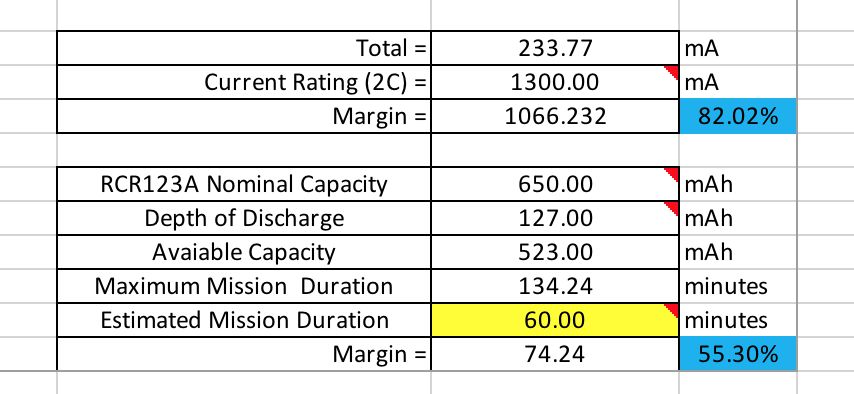 Fig. 3: Calculations for current draw and mission duration
Conclusion
The objective of this power template is to allow each project team to record all peripherals used in their project and their current draws. This template helps identify all current draws so the robot can operate efficiently without exceeding the battery values. Once all the values are inputted for each respective peripheral device used, calculations are automatically updated. The calculations are displayed towards the bottom of the document, see Fig. 3. All the information calculated includes total current draw and the maximum mission duration which is defined differently for each project.
References
- https://docs.google.com/spreadsheets/d/17oXC8C9Apr0KN9fGo3VRT38ZHFaBRNQnUWpWSYL1bdw/edit#gid=205608523
- http://www.ti.com/lit/ds/symlink/tps61200.pdf
- http://ww1.microchip.com/downloads/en/DeviceDoc/Atmel-7766-8-bit-AVR-ATmega16U4-32U4_Datasheet.pdf
- https://drive.google.com/file/d/18xenQLRR–v6t-eWHHrI-9tyA8uVhRLa/view
- https://www.arxterra.com/news-and-eventsmembers3dot-robots3dot-goliath/