Christopher Andelin (Project Manager)
Mario Ramirez (Systems Engineer)
Qui Du (Manufacturing Engineer)
Andrew Laqui (Electronics and Controls Engineer)
Henry Ruff (Electronics and Controls Engineer)
Executive Summary
Program Objectives & Mission Profile
By Christopher Andelin (Project Manager)
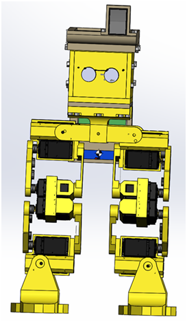
RoFi is the fifth prototype from Project Biped. It is a self-contained, bipedal robot that uses accelerometer feedback to balance. It has 12 DOF (degrees of freedom) and can walk around while avoiding obstacles using an ultrasonic range sensor. A small Android tablet in RoFi’s head provides the brains and an Arduino Mega provides the hardware interface.
The Design
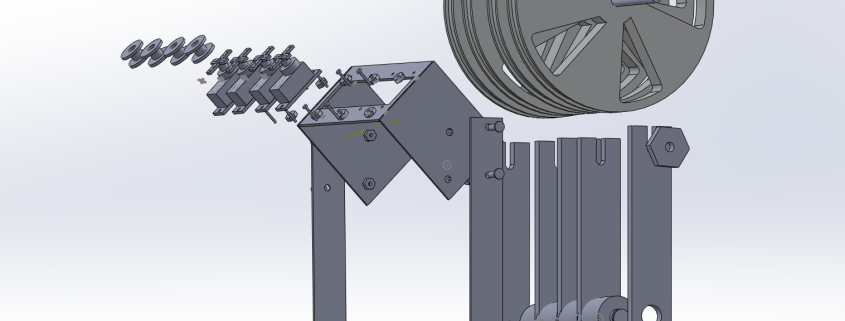
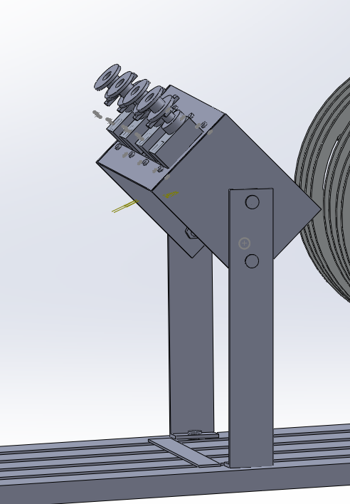
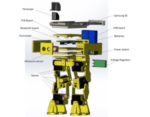
The figures below are our mechanical design and layout of RoFi.
Exploded View

Rear View
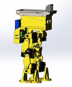
Right Side View
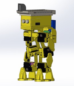
Left Side View
Project Features
Some key features of our design include:
- Redesigned head
- Battery Backpack
- Larger batteries for longer run time
- SMT PCB / Microcontroller
- Periscope provides vision
- RoFi must walk a figure 8 obstacle course
Some innovation of our design include:
- Mouse pad for shoes
- Designer glasses box for prototype head due to its ability to be shaped and retain form
- Servo locks are used to secure loose servos
System Design
System Block Diagram
By Mario Ramirez (Systems Engineer)
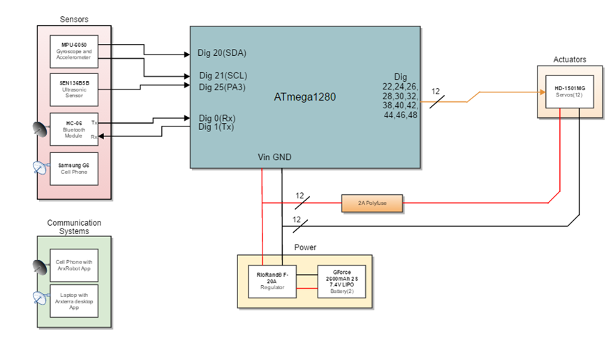
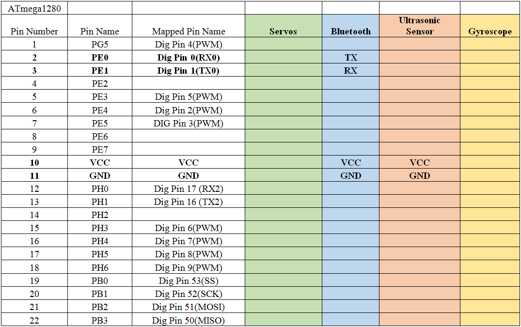
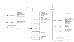
The Block diagram shows our system broken into sub-systems and how each sub-system is connected to complete the entire system. Pins for the Atmega chip can be verified through our interface definitions.

System Block Diagram
Experimental Results
Accelerometer / Gyroscope
By Andrew Laqui and Henry Ruff (Electronics and Controls Engineers)
The accelerometer/gyroscope MPU-6050 found here was tested by implementing the test code found here and reading the raw values that were printed through the Arduino IDE. Detailed instructions on how to use those raw values can be found here in Henry Ruff’s blog post.
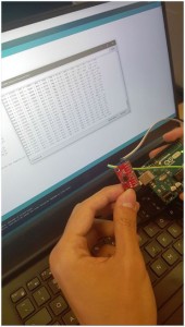
Accelerometer / Gyroscope
Ultrasonic Sensor
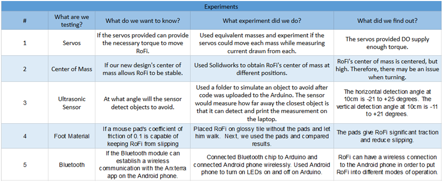
The ultrasonic sensor SEN136B5B was used on RoFi in order to detect and avoid objects. Various tests were performed in order to determine the range for which the sensor can detect. An in-depth explanation of these tests can be found here. The table below details the various angles that the sensor detected an object.

Ultrasonic Sensor Data
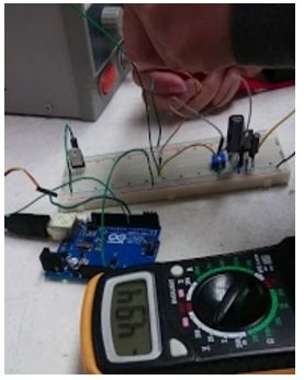
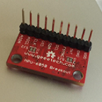
Servo Driver
The servo driver PCA9685 found here was tested because originally, an Arduino UNO was going to be used in order to reduce the size of the Arduino. Ultimately, rather than using an Arduino UNO, an ATmega1280 was implemented on the custom PCB design in order to accomplish this size reduction. A detailed description of how to servo driver was tested can be found here.
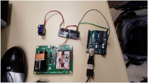
Servo Driver
Experimental Results
By Mario Ramirez (Systems Engineer)
Below is our table of experiments completed.
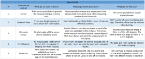
Experimental Results
Torque Testing
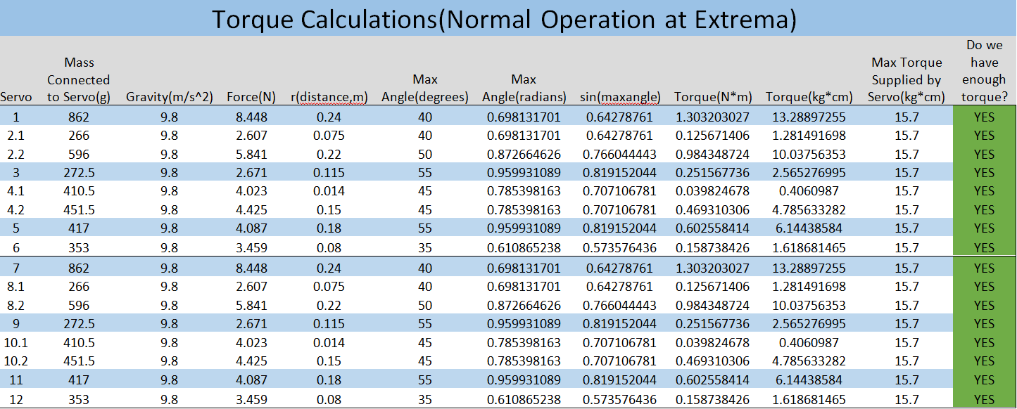
An analysis of the maximum torque needed to move each mass is done to insure RoFi’s servos can provide enough torque before stalling. Further information can be found here, https://www.arxterra.com/spring-2016-rofi-torque-report/.
This table shows the torque needed for each mass compared to the stalling torque of each servo.
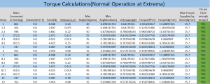
Torque Calculations
Center of Mass
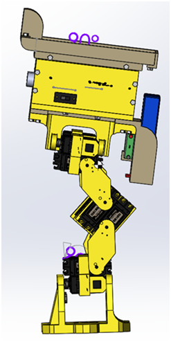
Center of Mass simulation was done to visualize RoFi’s center of mass with the new head design. The center of Mass is represented by the black and white circle. Further information can be found here, https://www.arxterra.com/spring-2016-rofi-center-of-mass-report/.

Center of Mass Side View

Center of Mass Front View
Subsystem Design
Interface Definition
By Mario Ramirez (Systems Engineer), Andrew Laqui and Henry Ruff (Electronics and Controls Engineers)
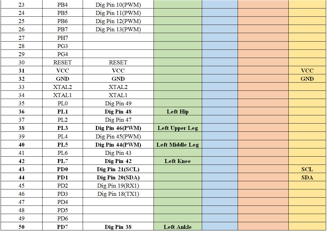
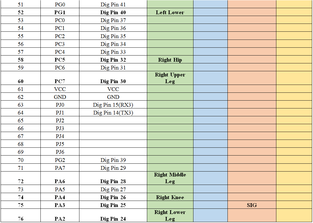
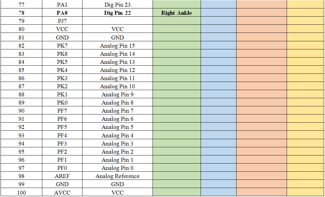
Below is our pin mapping for the ATmega 1280 chip.
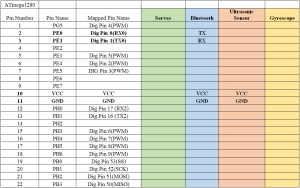
Interface Definitions 1a
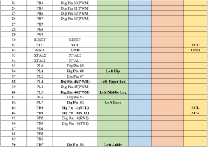
Interface Definitions 1b
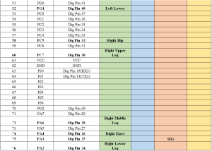
Interface Definitions 1c
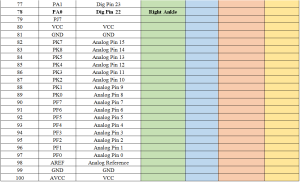
Interface Definitions 1d
Custom PCB / Microcontroller Design
Custom PCB Design
By Andrew Laqui and Henry Ruff (Electronics and Controls Engineers)
The beginning of the custom PCB design began with taking a look at how messy the physical breadboard was. Due to the number of servos (12), the wires needed to be carefully attached and handled in order to not have any wires disconnect.
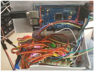
Messy Cables
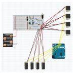
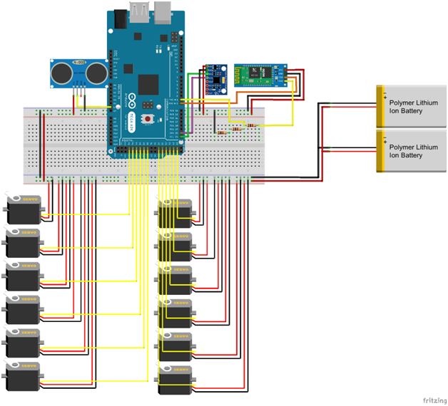
Using the free software Fritzing, a digital diagram of the breadboard was constructed. Various libraries were added to the original software because the free software did not provide a few of the required parts. Those libraries can be found in the links to the Custom PCB Blog below.

Fritzing Diagram
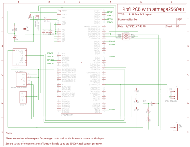
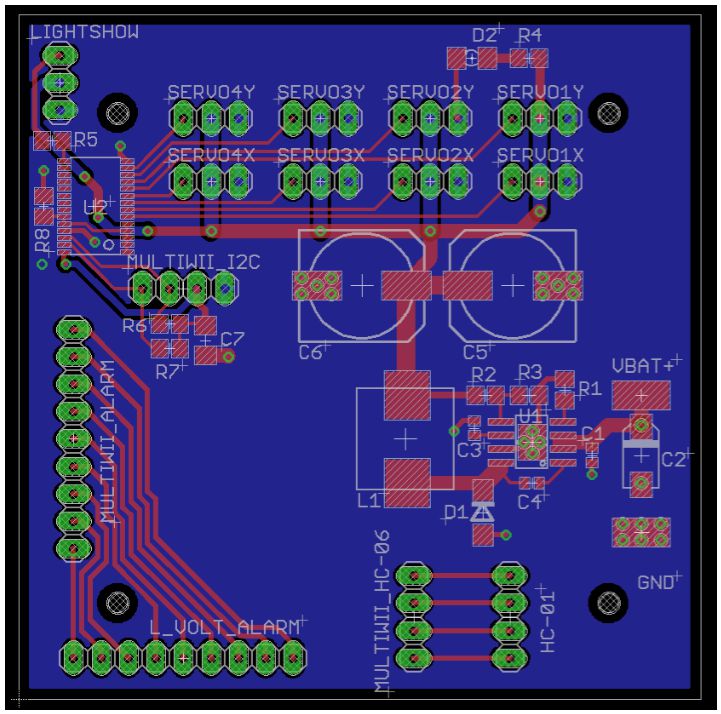
Next, using the free software EAGLE, a schematic was constructed including all of the components that will be used on RoFi according to the interface definitions. The schematic was then used to determine the finalized layout for the actual PCB. More information for the PCB Layout can be found in Qui Du’s PCB Layout blog post.

PCB Schematic

PCB Schematic Continued

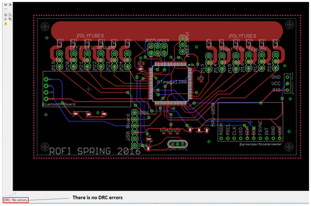
Finalized PCB Layout
Active Balancing of RoFi During Movement
By Henry Ruff (Electronics and Controls Engineer)
A large challenge for RoFi was the utilization of the MPU-6050 Accelerometer/Gyroscope while it was performing its active walking cycle. Because RoFi had to traverse a threshold, incline, and perform a figure-8 on such, it became very time-consuming and difficult to successfully replicate in separate run-throughs. As such, utilization of the MPU-6050 would have been able to make RoFi’s walking more reliable and easier, however, we were unable to successfully implement in. Instead, the following blog post elaborates on relevant efforts.
PCB Design
By Qui Du (Manufacturing Engineer)
I created the PCB layout once I received the PCB schematic from the Electronics and Controls Engineers. More detail about our PCB Design could be found here.
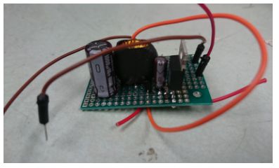
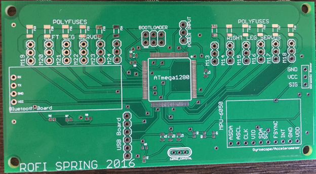
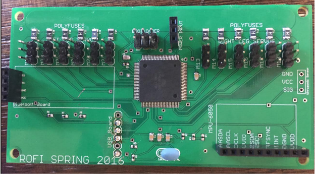
Soldering the PCB
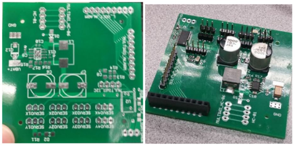
After generating Gerber files and ordering the PCB components, I sent the Gerber files to class president Ryland Watts. One and half weeks later, we received the PCB board and PCB components. I soldered the PCB board with help from the class president Ryland Watts and the manufacturing division manager Juan Mendez. Here is the result of PCB board before and after soldering.

PCB Before Soldering

PCB After Soldering
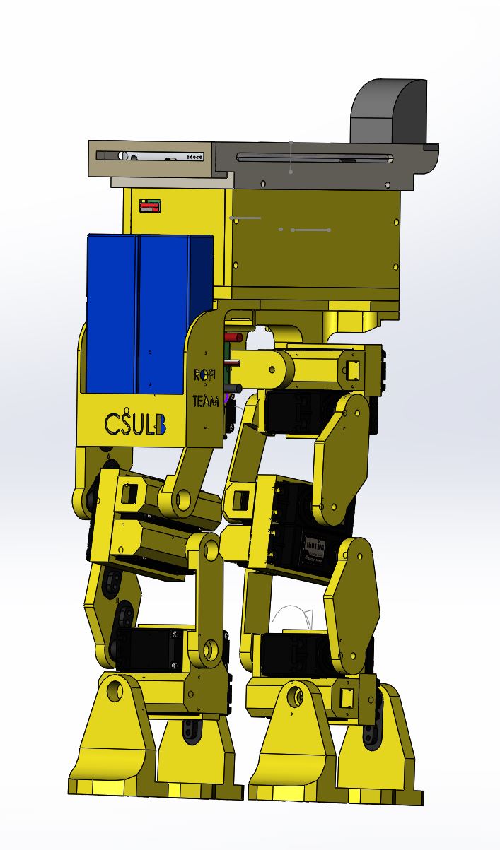
Hardware Design
My design decreases the size of the head and feet. Below is the completed SolidWorks 3D modeling of RoFi.
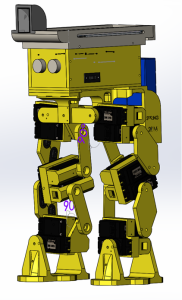
Complete RoFi Design
Detailed information about the design could be found here
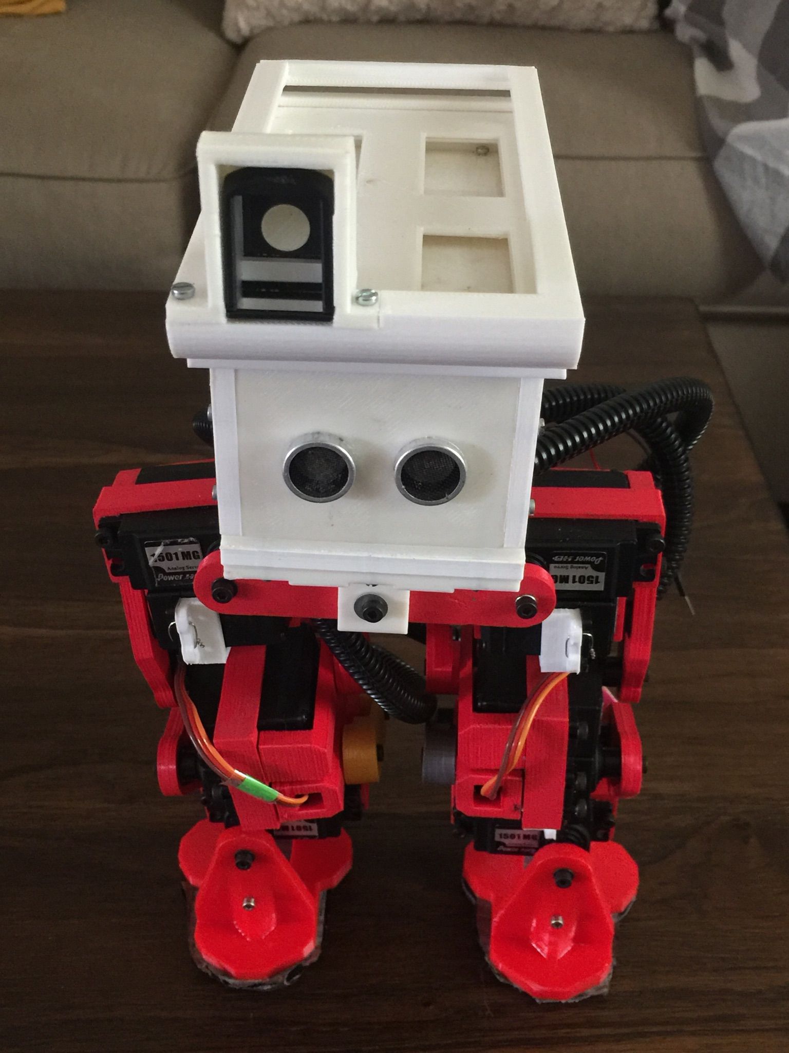
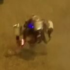
After generate the STL files and making STL repair using netfabb Basic, all parts were ready to print. Here is the final result of RoFi.

Complete RoFi
Software Design
Software Block Diagram
By Mario Ramirez (Systems Engineer)
Here is a flow chart of our software. The grey boxes are scripts written to handle the telemetry. This code is given to you by Hill. Blue squares represent the different subroutines for our code. The red boxes represent the type of pin each sensor or actuator is connected to. The orange squares represent the name and number of the pin each sensor or actuator is connected to. The yellow boxes represent our sensors and actuators. Green boxes represent what the user is controlling based on the software.
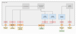
Software Block Diagram
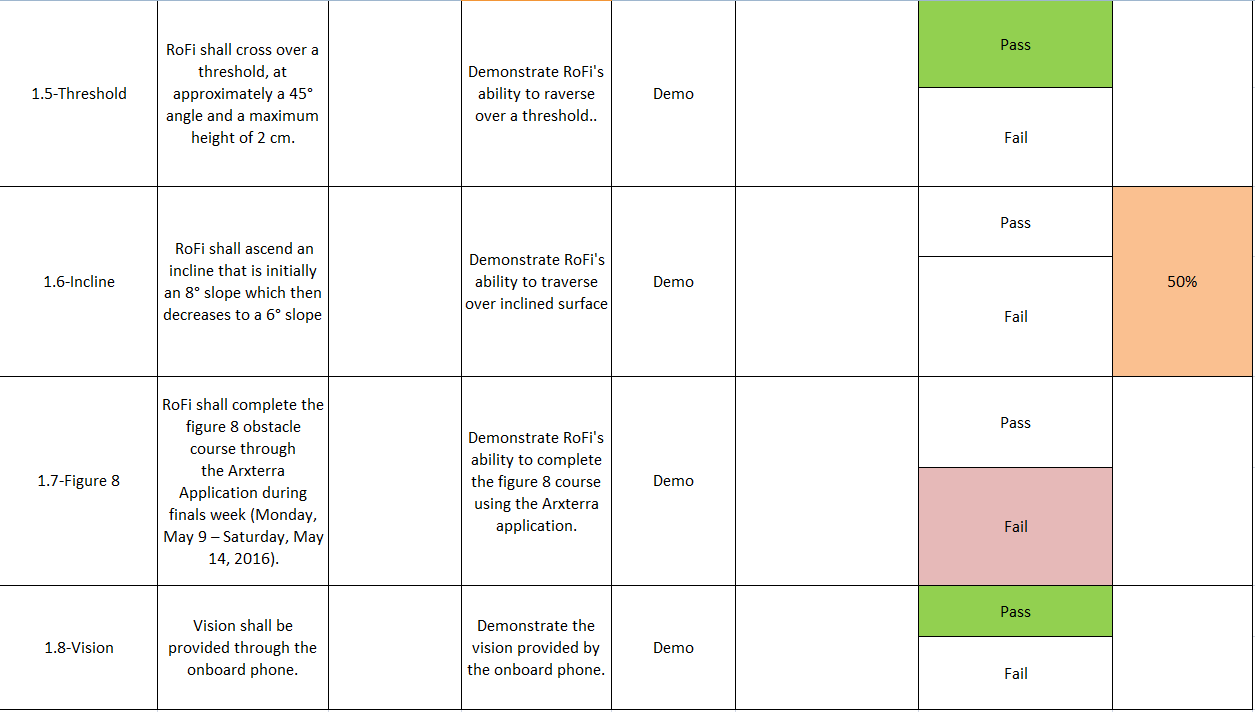
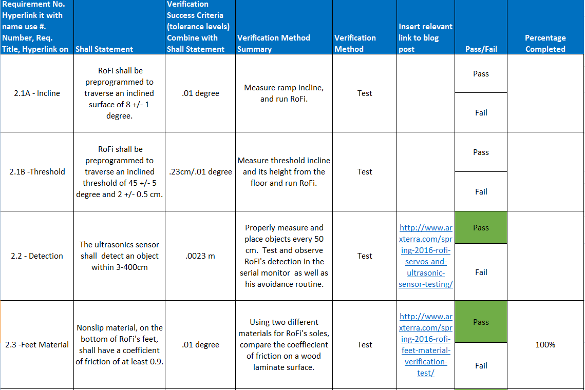
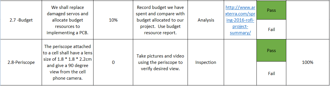
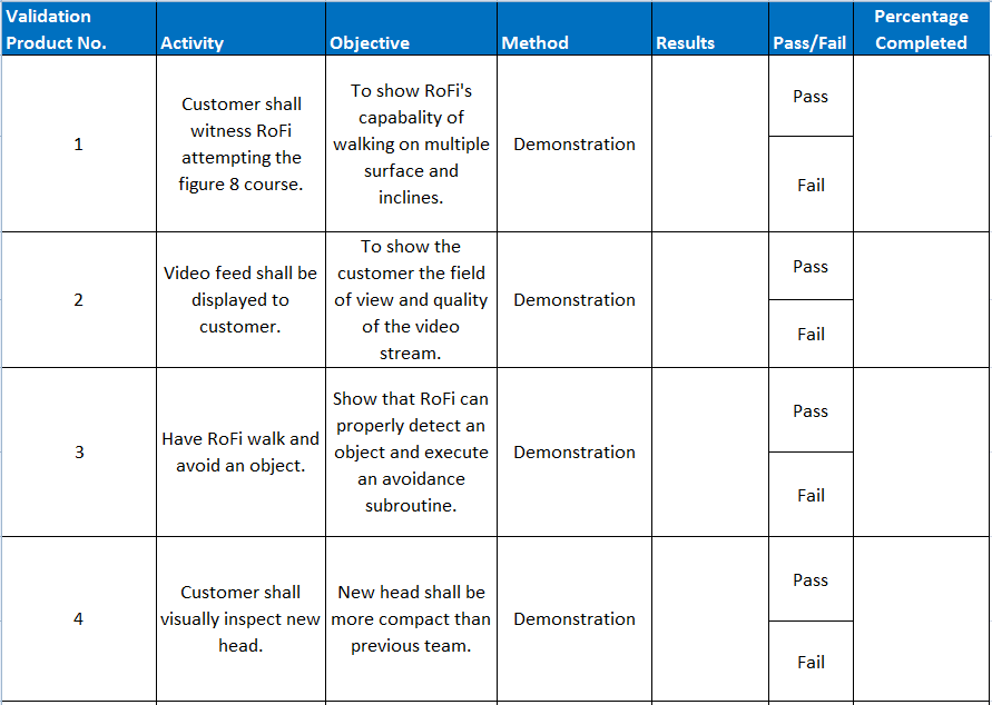
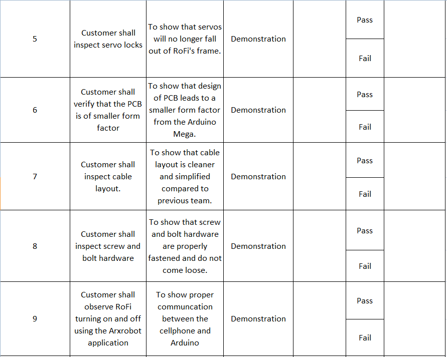
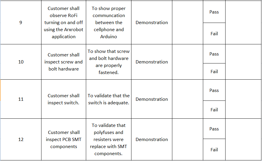
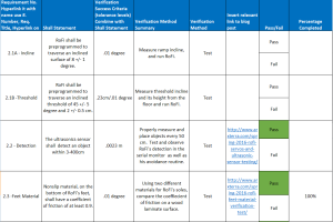
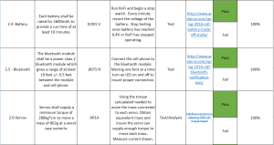
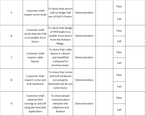
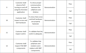
Verification & Validation Test Plan
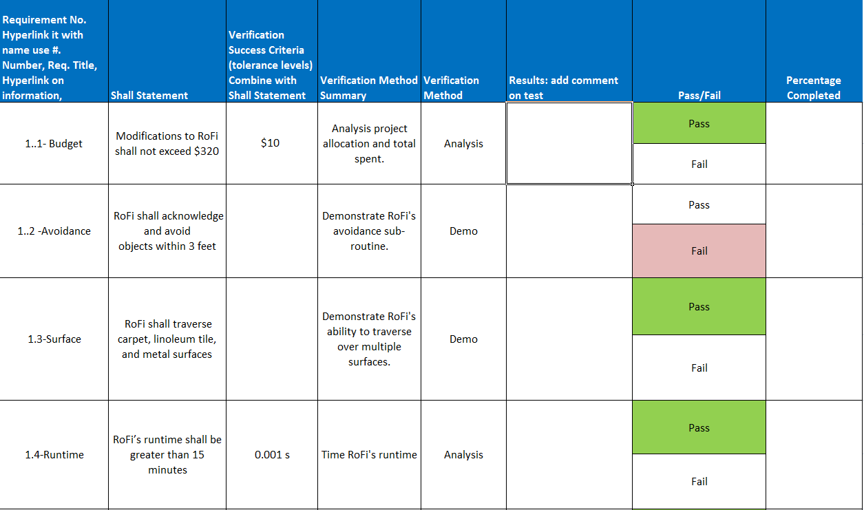
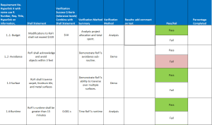
Verification and Validation are based off requirements that can be found here, https://www.arxterra.com/spring-2016-rofi-preliminary-design-documentation/
Note: The Pass / Fail and Percentage Completed columns is our teams opinion and not that of the customer.
Verification and Validation Req.1a

Verification and Validation Req.1b
Verification and Validation Req.2a
Verification and Validation Req.2b

Verification and Validation Req.2c

Verification Matrix 1a
Verification Matrix 1b
Verification Matrix 1c
Project Update
Work Breakdown Structure
By Christopher Andelin (Project Manager)
Below is our work breakdown structure.
Work Breakdown Structure
Resource Reports
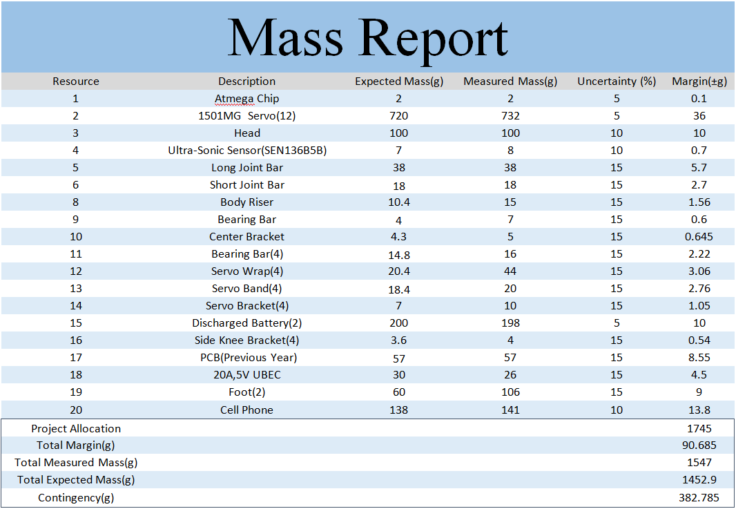
Mass Report
By Mario Ramirez (Systems Engineer)
Project allocation is based off of the maximum mass the servos would be capable of moving before stalling.

Mass Report
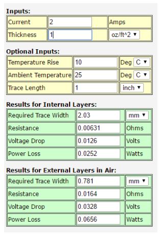
Power Report
Project allocation is based off of a 15 minute run time. This report assists in calculating what ratings you need for the batteries.
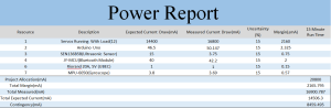
Power Report
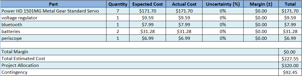
Budget Report
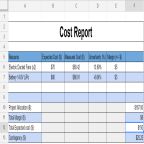
By Christopher Andelin (Project Manager)
Note: Our project cost does not include the PCB / Microcontroller and the components because our President bought them.
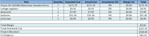
Project Cost
Schedule
Below is our project schedule.
View post on imgur.com
Schedule Summary
Here is my assessment on our overall progress:
- Mechanical Design 100%
- PCB / Microcontroller Design 100%
- Repaired issues with loose frame 90%
- Improved running time 100%
- Periscope lens 100%
- Polyfuse SMT 100%
- Organize cables 100%
- Moving parts hazard 0%
- Walking in a circle on flat surface 100%
- Surpass leveled surface to inclined surface threshold 100%
- Walking in a circle on inclined surface 25%
- Figure 8 obstacle course 30% (leveled surface circle only)
My overall assessment is that we are about 80% complete.
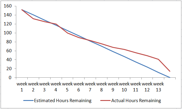
Burndown Chart
Our burndown chart dips in the last week due to getting the printed parts and PCB / Microcontroller implemented into our design. We still need to complete the figure 8, hence the reason why we are behind schedule.
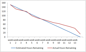
Burndown Chart
Concluding Thoughts
Since it is the end of the semester, I have some suggestions for future RoFi teams:
- Get approval for all purchases – Due to time constraints, our team was in a rush to get parts in to begin implementation. We focused our attention on completing our mission objective without considering our customers expectations. It is important to complete the objective as well as pleasing the customer.
- Replace servos with better quality – We had servo issues throughout the semester. We always had a spare servo in hand due to the unpredictability of servo failure.
- Make RoFi lighter – The servos would spasm causing RoFi to fall.
- Lower the center of mass – Due to RoFi being so top heavy, it was difficult implementing walking on an inclined surface.
- Avoid using Robot Poser – Robot Poser only worked on one of our team members laptops and we never found out why. Robot Poser was also difficult to get it to start. You may have to open task manager at times and close programs, plug and unplug the Arduino cable and the battery; I felt like we had to jump through hoops to get it to work.
- Implement the ultrasonic sensor, accelerometer/gyroscope and cordless walking – Due to customer request, we focused a lot of our attention getting RoFi to walk the figure 8 obstacle course and neglected other features.
- Get RoFi asap – We had to do a lot of documentation throughout the semester, we did not get to work on RoFi until about one month into the semester.
- Choose team members wisely – I was fortunate to have a great team but keep in mind that students have other classes and work to attend to. Interview students and select members that have time, transportation and money.
- Project Manager – As Project Manager I had a lot of paperwork in the beginning of the semester. Work slowed down in the third month, so I dedicated a lot of my time getting RoFi to walk and assisted the engineers where I could.
- Be cautious of free 3D printing – Verify that the quality of the 3D printing material is to your liking.
- Understanding the customer – Realize that the customer has multiple projects and classes and will claim things were said or were not said that you may need to address. Communicate and verify all concerns with the customer, student teacher and president.
- Update Mission Objective – Our mission objective said that the incline was 8 and 6 degrees; we measured the incline and it varied from 14 to 7 degrees. The room was also a burden to work in because the room was popular for labs and lectures.
Resource
Project Video
Bonus Videos
www.youtube.com/watch?v=96UEVOszRBs
Files
The following Google Drive contains useful resources for future RoFi teams, https://drive.google.com/drive/folders/0B_v74PMhdCbKSXVPQ285ekZEX28.