Spring 2018 AT-ST Line Follower Code

By: Samuel K. Yoo (Electronics & Control – Software)

Verified By: Intiser Kabir (Project Manager)

Approved By: Miguel Garcia (Quality Assurance)

Table of Contents

Introduction

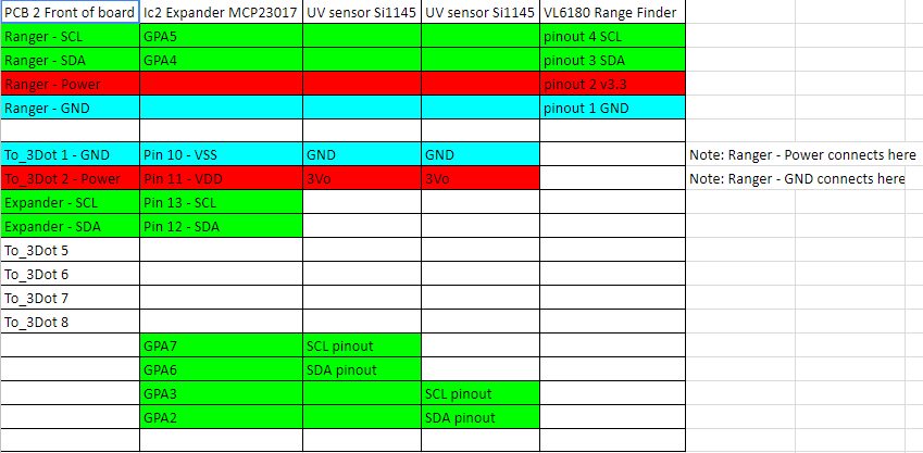
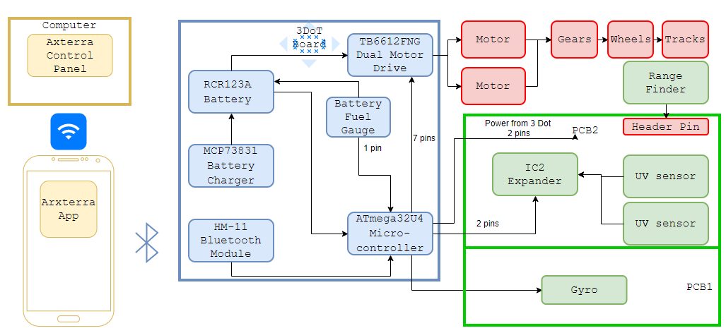
The main objective of this code is to make the robot follow a line. The initial part of the program has two motors turning wheels to move forward. After accomplishing this first part of the code, the next is to create the line follower. There would be four sensors not touching the line, and if the sensor hit the line, the robot would swerve away and continue to head straight. The AT-ST would not use motors for forwarding motion, instead, it uses servos. The four sensors will still be the same for the AT-ST.

Code

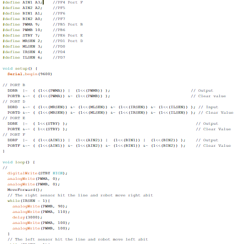
Figure 1: Code Screenshot

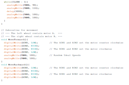
Figure 2: Code Screenshot cont.

Explanation

The beginning of the code initializes all the pin definitions and the I/O for each pin.  After that part of the program, the main loop contains the movement code. This code allows two motors to spin in opposite directions, attached to the wheels to move the robot forward. However, this movement code will be modified at a later date, as the AT-ST uses servos. The servos do not work like the motors and require a lot more analog pins. These pin requirements will need an analog extension. The sensor reading code, however, can mostly stay the same. The concept of slowing one part and increasing the speed of the other part will stay the same. However, it would not be the torque but the movement of the leg. Another huge difference in the code is the values. If this program would run on a robot right now it would crash or not move straight at all. This is because each motor is made with different values. There is no minimum value for the speed and the delay values might be too long.

Conclusion

So this line code main purpose is to move the robot forward and to follow a line. One of the issues is the AT-ST does not use motors for movement, it instead uses servos, which at the moment of this blog post, there is no research on. Another issue is the values inside the code are not accurate. These values need to be tested in real life to get value for the code. Overall, the general idea of the code in this blog post, however, needs to be updated with servos code and the real values in the final code.  

Spring 2018 AT-ST Power Budget

By: Joseph Cho (Mission, Systems, and Testing)

Verified By: Intiser Kabir (Project Manager)

Approved By: Miguel Garcia (Quality Assurance)

Table of Contents

Update: Figures have been updated to measured values.

Introduction

Power budget of the AT-ST project will be estimated using the power budget general template. The power budget will be estimated to determine the battery that should be used on the AT-ST. All of the values used in the power budget are measured using a current meter.

List of Parts

This is the list of all of the parts we are using as of today!

  • 3DoT Board
  • Bluetooth: HM11
  • Dual Motor Driver: DRV8835
  • (2) Motor: 50:1 Micro Metal gear motor
  • (2) Servos: HTX900
  • (2) Shaft Encoders : Pololu product 3081
  • I2C Expander: TCA9548A
  • Gyro : GY-521 (MPU6050)
  • Ultrasonic: HC-SR04
  • IR LED 1 (rated for 16~18mA)
  • Light sensor 1: Si1145
  • IR LED 2 (rated for 16~18mA)
  • Light sensor 2: Si1145

Power Budget Spreadsheet

Figure 2: The total Power In/Output of the system

Figure 3: Boost Parameters

Figure 4: Margin Calculation

Description

The current design for AT-ST uses 2 motors and 1 servo. The majority of the power is consumed by the motors and servo to move the AT-ST. The motors output power will be distributed by the motor driver. Four sensors will be used: UV, ultrasonic, shaft encoder, and gyroscope. The sensors will be using less power compared to the motors. Based on the estimated current consumption, a general power usage will be estimated using the power budget general template.

Measuring Current

Figure 5: Multimeter used to measure current

Description:

Rigol DM3058E digital multimeter was used to measure the current drawn by the components. The multimeter was tapped between the output pin of the microcontroller and VCC of the sensor.

Resources

  1. https://www.arxterra.com/news-and-eventsmembers3dot-robots3dot-goliath/
  2. https://www.sparkfun.com/datasheets/Components/LED/YSL-R547P4C-E3.pdf
  3. https://docs.google.com/spreadsheets/d/1WsdFps31TaSi-vaA3mB8fVlLQd3yEO-VCvbinQXoAG8/edit?usp=sharing
  4. https://docs.google.com/spreadsheets/d/1OaWtFrqYVQsylEh2nXOvKjFT-g2KG72ej-pF6OJWQ54/edit?usp=sharing

Spring 2018 AT-ST Resource Reports (Mass, Power, and Cost)

By: Joseph Cho (Mission, Systems, and Testing)

Verified By: Intiser Kabir (Project Manager)

Approved By: Miguel Garcia (Quality Assurance)

Table of Contents

Introduction

The resource report contains three parts: Mass report, power report, and cost report). These reports will be covering the resources’ mass, power, and cost. An estimate of the total mass will be shown on the mass report. For power report, the current values were taken from previous projects’ blog posts as reference. Lastly, cost report will show that the AT-ST project is within the budget.

List of Parts

  • 3DoT Board
  • Bluetooth: HM11
  • Dual Motor Driver: DRV8835
  • (2) Motor: 50:1 Micro Metal gear motor
  • (2) Servos: HTX900
  • (2) Shaft Encoders : Pololu product 3081
  • I2C Expander: TCA9548A
  • Gyro : GY-521 (MPU6050)
  • Ultrasonic: HC-SR04
  • IR LED 1 (rated for 16~18mA)
  • Light sensor 1: Si1145
  • IR LED 2 (rated for 16~18mA)
  • Light sensor 2: Si1145

Mass Report

Figure 1: Mass Report


Description:

Comparing our AT-ST to last generation of velociraptor, the mass will be around 800g. 3D printing mass is estimated on the mass report blog post. Since the custom PCB will be made with the same materials with 3DoT board, we can estimate that the mass of the PCB will be similar to the 3DoT board. Our main PCB is slightly smaller and two other sensor PCB are half the size. Further more information about how the masses were estimated and weighed are in Mass report blog post. There are also couple of measured weight as 0. This is due to those parts being included in the body of the mass measurement.

Power Report

Figure 2: Power Report

Description:

The power report shows the expected current draw needed from the power supply. Each servo is rated at 270 mA with a load. The 3DoT board current draw is also counting these parts: Bluetooth and dual motor driver. Measured currents have been added. The motor uses 29mA with load and 170mA when stalled. Power budget was used to determine if a battery with higher capacity was needed.

Link to Power Budget

Cost Report

Final Cost

Figure 3: Cost Report

The cost report shows the total expected cost to be slightly more than half of the budget. After totaling up the spendings, we are still under the budget of $250. There are some components that are given or borrowed; therefore, the actual cost is zero for those items. Our total cost for the AT-ST materials is $199.58 with shipping included.

Extra Cost

Figure 4: Extra costs (included in Cost Report)

Description:

There were additional costs to AT-ST, but not included in final cost report because these resources were not used on the AT-ST.

Conclusion

The reports show that the AT-ST had all resources within the project allocation. The final mass of AT-ST was 256.80 grams, which is very light compared to 2nd generation of Velociraptor. Total cost of the final product was $199.58 and the prices could have been lowered if parts were ordered earlier.

Resources

  1. http://www.custompcb.com/faq.php
  2. https://docs.google.com/spreadsheets/d/1_q0K2hwcqDshcp3e7MT1azD3lbXh80qJeSJ1bALZQZ0/edit?usp=sharing
  3. https://docs.google.com/spreadsheets/d/1P0TaSyV01-3muaii-rDUmqtotstaM6gV4AgC4sjzqFQ/edit?usp=sharing
  4. https://docs.google.com/spreadsheets/d/1j9I_ts227pN5yA5srDkUxOWhMTKYiYWG9uBwJw8IQA8/edit?usp=sharing 

Goliath Spring 2018 – Power Budget

By: Ryan Nguyen (MST Engineer)

Verified By: Ernie Trujillo (Project Manager)

Approved By: Miguel Garcia (Quality Assurance)

Figure 1 – Power Budget for the components of the Goliath.

Version 6.x of the 3DoT board does not include an LDO component, thus several changes were made to the power budget to reflect that change. All of LDO related currents and voltages were deleted, making the template much simpler. To calculate the power budget out the template, current draw of each subsystem must be obtained, by either measurement or data sheets. The template then takes those measurements and calculates the margins of power dissipation, output current, and how long the battery would last. Several assumptions were made, such as the EFFboost, the efficiency of the buck/boost converter, UVLO, FET switch limit, and inductor saturation.

Since Goliath does not use a servo, we won’t have a current draw from it. Regarding margins, there are three that we considered. From top to bottom and left to right: The first is heat safety margin. Our application dissipates 41.62 mW while the max is 971 mW so we are almost 96% safe. The second margin is the boost converter and its supply current margin; boost converter is able to supply plenty of current with a 91% margin. Third, is the margin is maximum instantaneous current the battery can supply, at 1300 mAH, we have a 78.46% margin. Lastly, we have a huge margin on runtime where we are able to operate at 112 minutes, twice the mission duration of 1 hour.

AT-ST Mass Report

By: Joseph Cho (Mission, Systems, and Testing)

Verified By: Intiser Kabir (Project Manager)

Approved By: Miguel Garcia (Quality Assurance)

Table of Contents

Introduction

This blog post will show the mass of the AT-ST and include the ways that the masses have been initially estimated. All of the parts have been measured for the final mass report.

Mass resource report

Figure 1: Mass Report

Description:

Mass of the AT-ST has been estimated by the given masses on the retailers. The 3D printed parts were estimated by rough calculation shown below. PCB mass was estimated by comparing the size to the 3DoT board size.

All of the parts have been measured on the AT-ST. The total mass came out to be 256.80 grams. There are some parts that have been listed as 0 grams because they have been put together in the body weight.

Measuring the Mass

Figure 2: Scale used to measure the mass

Description:

Ozeri pronto digital scale was used to measure the mass of our components. The scale had to be placed on a leveled surface and calibrated by pressing “TARE” button. The weight of the parts was rounded to the nearest gram. I would recommend a scale that has more accuracy for lower masses.

Theo Jansen Leg Dimensions

Figure 3: Theo Jansen leg concept

Description

With the Theo Jansen leg dimensions, we are going to estimate the volume of each legs to find the mass of the legs. The Theo Jansen legs will have a width of 3.96875 mm and thickness of 3.825mm.

Theo Jansen Leg 3D mechanical drawings (from mechanical drawing blog post)

Figure 4: Theo Jansen Leg 3D mechanical drawing

Body (housing for 3DoT and PCB)

Figure 5: Estimated Body Volume

Calculations

Figure 7: Mass Calculations for supports and Joints

Figure 8: Total Mass for one Leg and Joints

Figure 9: Total Mass Calculation for body (box)

Description:

The legs and body calculations were done by estimating the volume of the 3D printed parts and multiplying their density to them. Since 3D prints do not fill the parts completely with the material, the estimate of the mass will be higher than the actual weight. The mass of the AT-ST 3D printed parts will be around 253 grams for the box and 120 grams for the legs.

Resources

  1. http://www.strandbeest.com/beests_leg.php
  2. http://www.psyclops.com/tools/technotes/materials/density.html
  3. https://docs.google.com/spreadsheets/d/1l4bPs0FaRDSLj46PryDBNb4UZcGDcVGFgoV37JaNrXk/edit?usp=sharing

Goliath Spring 2018 – Mechanical Drawings

By: Daniel Guerrero (M&D Engineer)

Verified By: Ernie Trujillo (Project Manager)

Approved By: Miguel Garcia (Quality Assurance)

Figure 1 – Preliminary sketches for the Goliath Tank.

The reason behind this design was to follow the concept of the spring 2016’s design, to create a box shell of the tank as a preliminary design and attempt to fit all of the equipment inside. I tried to steer away from just a simple box for this design and tried to follow the general shape of the German 302 goliath tank. As for the placement of all the gaps in this design, I was aiming to have it accessible enough to configure all of our equipment into the design. For this first edition, I kept the size to five inches in length by four inches in width and about three inches in height.


Goliath Spring 2018 – Interface Matrix

By: Ryan Nguyen (MST Engineer)

Verified By: Ernie Trujillo (Project Manager)

Approved By: Miguel Garcia (Quality Assurance)

The interface matrix shows how each subsystem of Goliath connects to the ATmega32U4 microcontroller. The top header consists of the sub-systems, the left column has the name and pin number of the ATmega32U4. The matrix maps out how each pin is connected.


From the ATmega32U4, the version 6x 3 dot board specifies 16 pins that students can use for their robots. The first matrix shows the two PCBS of Goliath that will be connected to the three dot board, the top header shield, and the front sensor shield.

Figure 1 – Interface matrix of ATmega32U4

The second matrix shows how the components of the sensor shield will be connected; Goliath uses two UV sensors, as well as a range finder to navigate the maze.

Figure 2 – Interface matrix of front sensor shield

Lastly, Goliath uses a gyrometer, connected to the top PCB, to determine turning in the maze.

Figure 3 – Interface matrix of top header shield

Goliath Spring 2018 – Fritzing Diagram

Written by Milton Ramirez (E&C Engineer)

Verified by Ernie Trujillo (Project Manager)

Approved by Miguel Garcia (Quality Assurance)

Figure 1 – Fritzing Diagram for the Goliath Tank.

Parts

  • Pro Micro
  • Motor driver
  • Gyro
  • Range-finder  
  • Multiplexer
  • Bluetooth
  • Color sensor
  • Battery


Description

This a prototype of how we will connect the parts we are going to use, but some of these parts might not make the final design. In this prototype, our processor will be the pro-micro instead of the 3Dot board, since Professor Hill is still working on the 3dot board. Also, for that same reason, we will have to use a Bluetooth circuit for our prototype since the 3dot has Bluetooth implemented in it. We will probably have to use this configuration for most of our testing since we won’t get the 3dot until later in the semester. Also, we have a motor driver to control our motors. We are also using a multiplexer for our sensor, which is a Gyro sensor and a color sensor. Then we also have a range-finder, which this and the color sensor are floating outside on purpose, because the color sensor goes in the bottom of the Goliath. The range-finder will be somewhere in the front. Also, the specific part number is not included since that will also change for the last design.

References

  1. http://fritzing.org/home/
  2. https://www.sparkfun.com/products/12587


Goliath Spring 2018 – Planning and Scheduling

By: Ernie Trujillo (Project Manager)

Approved By: Miguel Garcia (Quality Assurance)

Table of Contents

Introduction

To achieve mission success for the Goliath Tank, a Gantt Chart was created by the Project Manager; the chart depicts all the pertinent tasks that need to be completed before attempting the mission through the maze. With the Gantt Chart, the Project Manager was able to take the tasks from the Task Matrix and display it in a visual chart that depicts the amount of time that is allotted per task and during what time of the semester this task will be worked on.

Figure 1 – Gantt Chart (1/3), these tasks mainly focus on being prepared for the Preliminary Design Review


Figure 2 – Gantt Chart (2/3), tasks that are pertinent to implementing the hardware to the Goliath.


Figure 3 – Gantt Chart (3/3), tasks that focus on software implementation and final verification of the Goliath.

Broad Layout of Project Schedule

Phase 1 (Research), Weeks 1-5:

  • Look through blog posts from prior semesters on Arxterra website for useful information that the current team can implement.
  • Begin developing level 1 & 2 requirements to meet mission objectives and customer expectations.
  • Begin layout for all tasks required to reach mission success at the end of the 16th

Phase 2 (Preliminary Design Review), Weeks 6 – 8:

  • Achieve a thorough schedule to lay out all tasks required to be complete by the team to bring the project to fruition.
  • Accomplish preliminary tasks: preliminary 3D model, system block diagram, Fritzing diagram, mechanical drawings, resource reports, work and product breakdown structure.

Phase 3 (Rapid Prototyping), Weeks 9 – 12:

  • Design multiple iterations of Goliath Tank to make the final product more efficient.
  • Create a program that will integrate all systems that are in the system block diagram. Also, ensure that the program will have the robot operate in a manner that meets mission objectives.
  • Have E & C Engineer work on creating and finalizing custom PCB.
  • Have MST Engineer work on Arxterra custom command and telemetry (Application side)

Phase 4 (Final Product & Mission Success), Weeks 13 – 16:

  • Finalize Goliath Tank 3D model and ensure that all systems are working properly.
  • Complete Project Video that shows the progression of project and implementation of the Engineering Method.
  • Complete Final Blog Post which displays a comprehensive overview of the Goliath project from start to finish.
  • On the day of the Final, demonstrate that the Goliath can navigate through the maze and meet all the L1 & 2 requirements.

References

  1. https://www.projectlibre.com/
  2. Task Matrix

Goliath Spring 2018 – System Block Diagram

By: Ryan Nguyen (MST Engineer)

Verified By: Ernie Trujillo (Project Manager)

Approved By: Miguel Garcia (Quality Assurance)

System Block Diagram

Figure 1 – System Block Diagram for the Goliath Tank.

The system block diagram illustrates how components of the Goliath communicate and connect with each other; from the control panel that uses Wi-Fi to talk with the mobile app to the wheels and treads. More detailed specific components such as the HM11 Bluetooth model is added, and various parts on the PCB parts are laid out; more items are expected when the E&C engineer completes trade-off studies. The 3DoT board houses a rechargeable battery that powers the motor driver and the Atmega32U4, which in turn powers the PCB. The number of pins is listed to demonstrate a rough idea of how many pins are required and create a rough layout for the interface matrix.