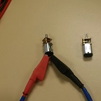
In this test, I will be testing the n20 motors at various voltages. The motors are rated for 6 volts, but the operating boosted voltage on the 3Dot board is 5 volts. The battery is rated at 3.6 volts, should we tap directly into the battery, but is typically fully charged at 4.2 volts [1]. The discharge cutoff voltage is at 2.75 volts, but wanted to test it at a slightly higher output of 3 volts.
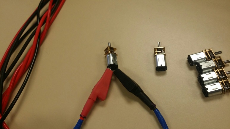
Figure 1. Applying Voltage to the Motor
Results
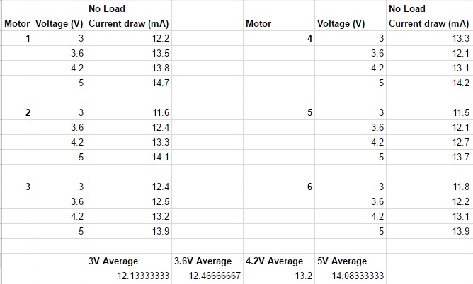
Figure 2. Voltage and Current Results
Conclusion
There is no significant change in the current draw from the different voltages on all the motors. Since the 3Dot motor connectors will use the 5 volts from the boost converter, we will most likely utilize the same voltage output so that all the motors will spin at the same rate. This is an easier solution than programming the onboard motors to spin at the same rate that the other motors.
https://www.arxterra.com/wp-content/uploads/2017/05/motor-Voltage-testing-thumbnail.jpg144144John Her/wp-content/uploads/2013/04/Arxterra-Logo-340x156.pngJohn Her2017-05-20 12:04:162018-03-09 07:35:24Spring 2017 Mini Pathfinder Motor no Load Current and Voltage Test
By: Oscar Ramirez (Mission, Systems, & Test)
-Body
Edited and Approved By: Jesus Enriquez (Project Manager)
-Introduction & Conclusion
Table of Contents
Introduction
One of the other challenges that we faced on top of choosing and configuring a color sensor was the challenge of interfacing the Arxterra app custom telemetry with the count dots command. This post covers the strategy and solution we came up with in order to solve this issue.
Requirement L2-1: The Velociraptor shall be able to count the number of dots it encounters in the Custom Maze using an SMD LED to indicate that it counted a dot Requirement L2-2: The 3DoT shall send custom telemetry to the Arxterra Control Panel via Bluetooth
Detecting the Red Dots
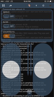
After configuring our TCS34725 color sensor we needed to implement this into our main code and not just detect the red dots inside the maze, but also count them and find some sort of way to display them. Implementing the red dot detection into the main code was not an issue but displaying the number of counted dots proved to be more of a challenge. A seven-segment display would not be ideal since it would require numerous digital pins on our Arduino and we would also need two seven segment displays to count a practical amount of dots. A much simpler solution would be first counting the dots and display the counted dots by blinking an LED equal to the number of dots counted. For example if we were to collect 14 dots the LED would blink 14 times. To enable this dot count, I created a custom Boolean command that once switched to “ON” would blink the LED the same number of times that are equal to the total dots. Creating a counting dot subroutine and inserting this logic was simple. First I copied the dot counter into a dummy variable so that the value of the counter would remain unmodified. Taking this dummy variable that has the total number of dots that we want to count, I inserted it into a while loop that begins by decrementing it by one and then flashing the LED once. This process repeats until the value of the dummy variable is equal to zero and the LED has flashed the same number of times equal to the total dots counted.
Figure 1: Our custom command that toggles the current red dot count
CountDotsHandler:
void countDotsHandler (uint8_t cmd, uint8_t param[], uint8_t n)
{
d=c; // copying number of dots to dummy variable
if (d>0) // counting the number of dots by derementing d
{
while (d>0)
{
d=d-1; // subtracting each dot one by one and setting LED to HIGH for each dot
digitalWrite(8, HIGH);
delay(250); // 250ms delay between LED flashes
digitalWrite(8, LOW);
delay(250); // repeating loop until all our dots are counted
}
}
}
Conclusion
This test for us worked fairly well off the robot and the only challenging aspect of this that we came across was that we did not test the robot for a static walk performance in order to predict about how long we should allow the LED to stay on as it encounters each dot. For the future, the best recommendation is to focus on getting the robot to walk first and foremost.
https://www.arxterra.com/wp-content/uploads/2017/05/soludot.jpg144144Jesus Denriquez/wp-content/uploads/2013/04/Arxterra-Logo-340x156.pngJesus Denriquez2017-05-20 07:59:292018-03-09 08:18:58Spring 2017 Velociraptor: Counting the Number of Dots Encountered
By: Oscar Ramirez (Mission, Systems, & Test)
-Body
Edited and Approved By: Jesus Enriquez (Project Manager)
-Introduction & Conclusion
Table of Contents
Introduction
One of the bug requirements that we needed to satisfy for our Velociraptor was giving it the ability to perform a turn in order to navigate the maze. To solve this issue we decided to integrate servos into the robot to turn the hip through the universal joint. This post covers a brief background on the testing we performed through the arxterra app to control the servo for the turn.
Requirement L2-8: The Velociraptor shall be able to turn.
Servo Control
For our velociraptor to turn we needed a servo to control the hip motion to an appropriate angle so that the robot could take a step with the hips turned and take another step with the hips back to their regular state to complete the turn. To control this hip motion a servo motor was the ideal solution.
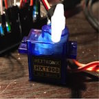
To begin I included the servo library in my code and declared servo11 as my servo. Next I created a handler and subroutine for this servo. A servo motor will typically only rotate from 0 to 180 degrees and for our purpose we would only need it to go from 0 to about 15 degrees to complete the hip motion. Using a Boolean command from the Arxterra app I set two angles, 0 and 15 defining 15 as “ON” and 0 as “OFF”. Finally using the pwn pin 11 on the Arduino I set up the servo and tested the range of motion with the Arxterra app going from 0 to 15 (toggling the on and off switch).
After performing this test, we were able to successfully send commands to the servo to turn a specific amount of degrees as required. The only thing that was the set back in this test was that there was a lot of iterative designing going on throughout the mechanical assembly of the robot so it did not leave us with enough time for full-proof testing. This provided proof of concept for our robot. This is why it is consistently recommended to focus on the mechanics of the robot more than anything before diving into the servo testing for turning.
By: Andrea Lamore (Manufacturing) Edited & Approved By: Jesus Enriquez (Project Manager)
Table of Contents
Introduction
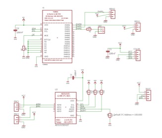
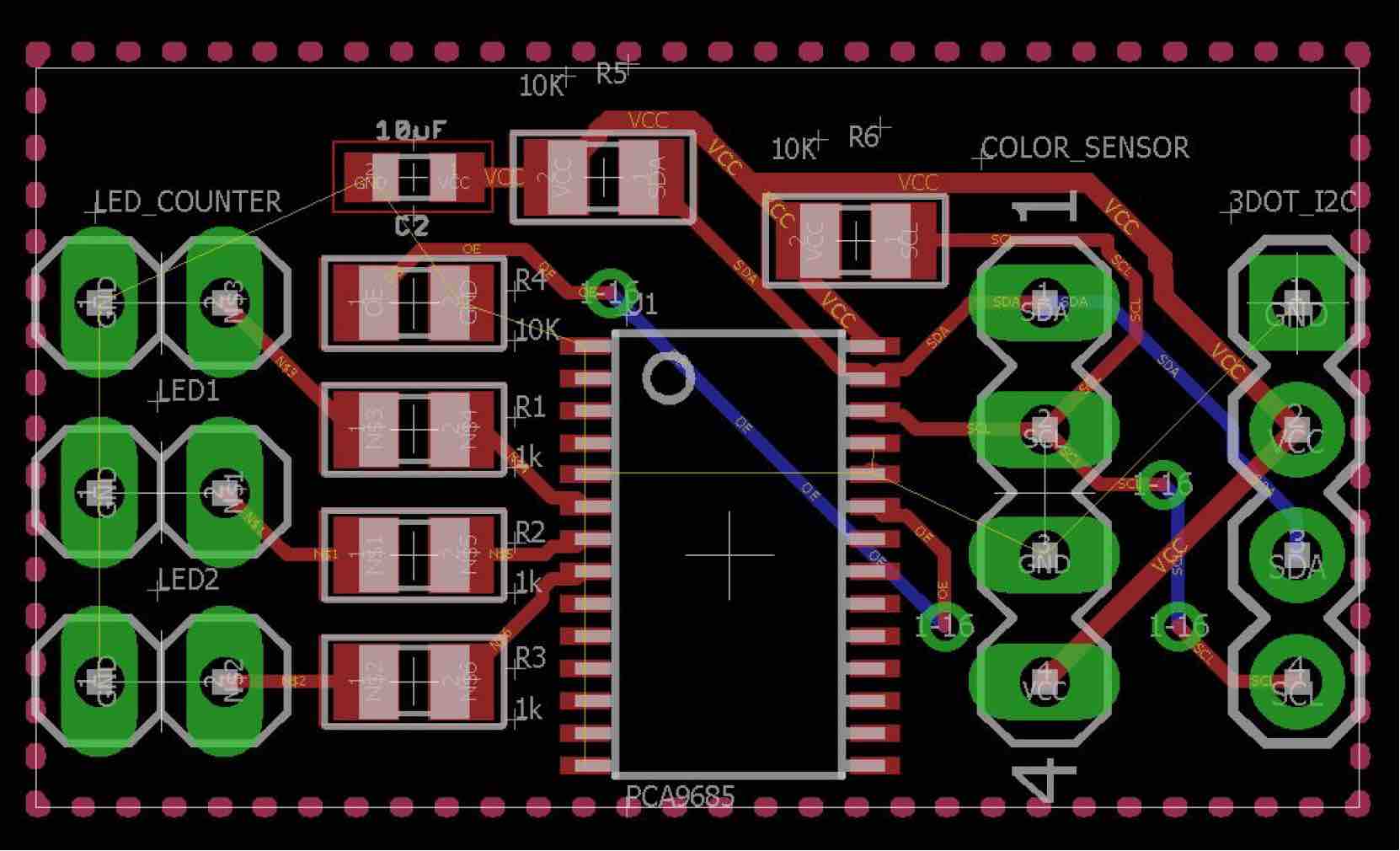
We had to build a custom PCB. Our PCB contained a 12 channel PWM expander the communicated with the peripheral devices that the 3Dot board did not have pinouts to hold. It was important to make sure everything on the PCB was I2C compatible so that the 3Dot board could communicate with it via only 2 pins. Netted to the PWM expander is an LED, potentially 3 servos, a color sensor, 2 rotary encoders, and an A2D converter for the rotary encoders.
Requirement L1-5: The Velociraptor shall use a custom PCB
Body
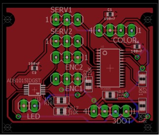
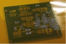
Below is the schematic and the PCB design
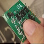
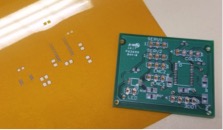
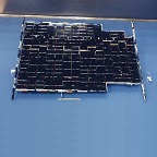
The Board we ordered and the stencil
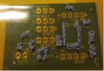
Surface mount soldering.
Solder pasts is layered over the stencil on to the PCB and then heated in the oven. Before laying out paste the stencil and PCB need to be secured with tape. After the paste is spread flat over the stensil with a credit card the stencil and the tape can be peeled off. The parts I was working with were about the size of a grain of rice, this is a reasonable size if one is hand placing parts. However, one of the capacitors I had to lay over the PCB was the size of a grain of sand, in these instances it makes more sense to use a Pick-and-place. If you do not have access to a pick and place make sure you are aware of the sized components you are ordering.
After the parts are placed over the solder, the board can be placed in the oven until the solder turns a shiny metallic color.
With Unheated Paste and Components
Note that is soldering you PCB with paste is not something to guess at. Soldering the PCB requires a lot of visual observation and attention to detail. You must use your best judgment to ensure that there are no shorts after heating up you board. Most of the teams fail the first time because they treat soldering the PCB more like a step-by-step procedure rather than an art.
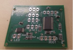
After placing PCB in Toaster oven for a couple minutes
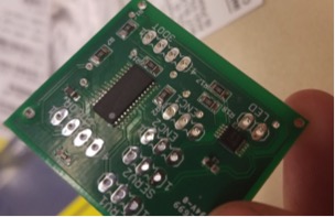
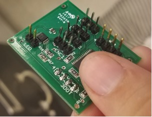
After I attached the through-hole components with a solder iron.
Conclusion
If I could redo the PCB I’d collaborate more with the EnC so that the parts ordered are a reasonable size so that they could be easily hand soldered onto the board. I’d add a more complicated display to the PCB (probably 2 seven segment displays) and more LEDs. I’d use an LED instead of a header. I’d use screw clamps for the power supply instead of a headers- since they hold easier. I’d include some control buttons/switches so I could potentially program various setting for the Velociraptor and change them easily by adjusting the switches on the PCB and resetting the board with a push button.
https://www.arxterra.com/wp-content/uploads/2017/05/PCB8-300x231-1.jpg144144Jesus Denriquez/wp-content/uploads/2013/04/Arxterra-Logo-340x156.pngJesus Denriquez2017-05-20 07:57:242018-03-09 08:18:58Spring 2017 Velociraptor: Schematic, PCB, and Construction
By: Andrea Lamore (Manufacturing) Approved By: Jesus Enriquez (Project Manager)
Table of Contents
Introduction
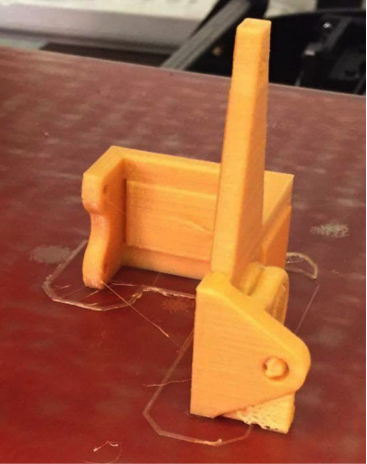
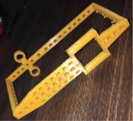
Assembly of the first velociraptor demonstrated some problems that were not clear from the SolidWorks model alone. These problems included a wobbliness/loose motion of the legs, the hip joint was arching when it should have been straight, and the head and tail were bending and lacked stability. In order to increase the stability of the velociraptor I made some changes to the design.
Requirement L1-3: The Robot should resemble the embodiment of a Velociraptor
Body
Assembly of the first velociraptor demonstrated some problems that were not clear from the SolidWorks model alone. These problems included a wobbliness/loose motion of the legs, the hip joint was arching when it should have been straight, and the head and tail were bending and lacked stability. In order to increase the stability of the velociraptor I made some changes to the design.
Above, on the first assembly, you can see the head and tail that will now be used only aesthetically. Below is the second Assembly with no electronics attached.
I increased the width of the hip socket so the u-joint wouldn’t bend vertically. Two ball bearing were to be used on each side.
I added stabilizers to the leg so the circle would remain vertical. I also cut the circle large enough to reach the stabilizers without interfering with the shaft motion.
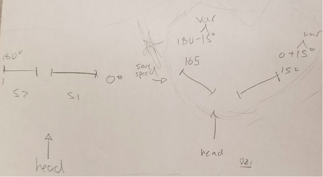
A single servo should be able to move the hips, however 2 servos will be attached and move in sync to increase torque. This requires that they be attached at 90 degrees then move plus and minus 15 degrees respectively depending on whether the legs are turning out or in.
I used thicker acrylic sheeting for the new leg cuts and reduced the size of the shaft holes to the minimum size that could fit a 6-32 screw (which I used for the shaft).
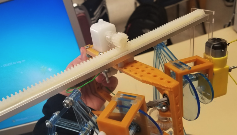
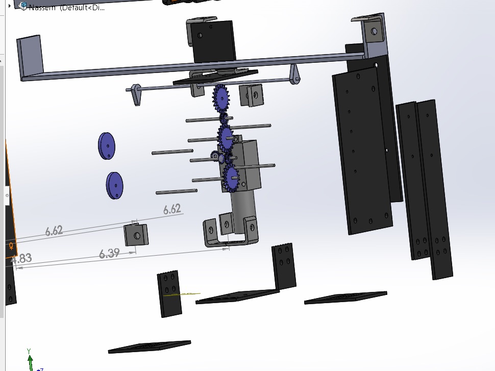
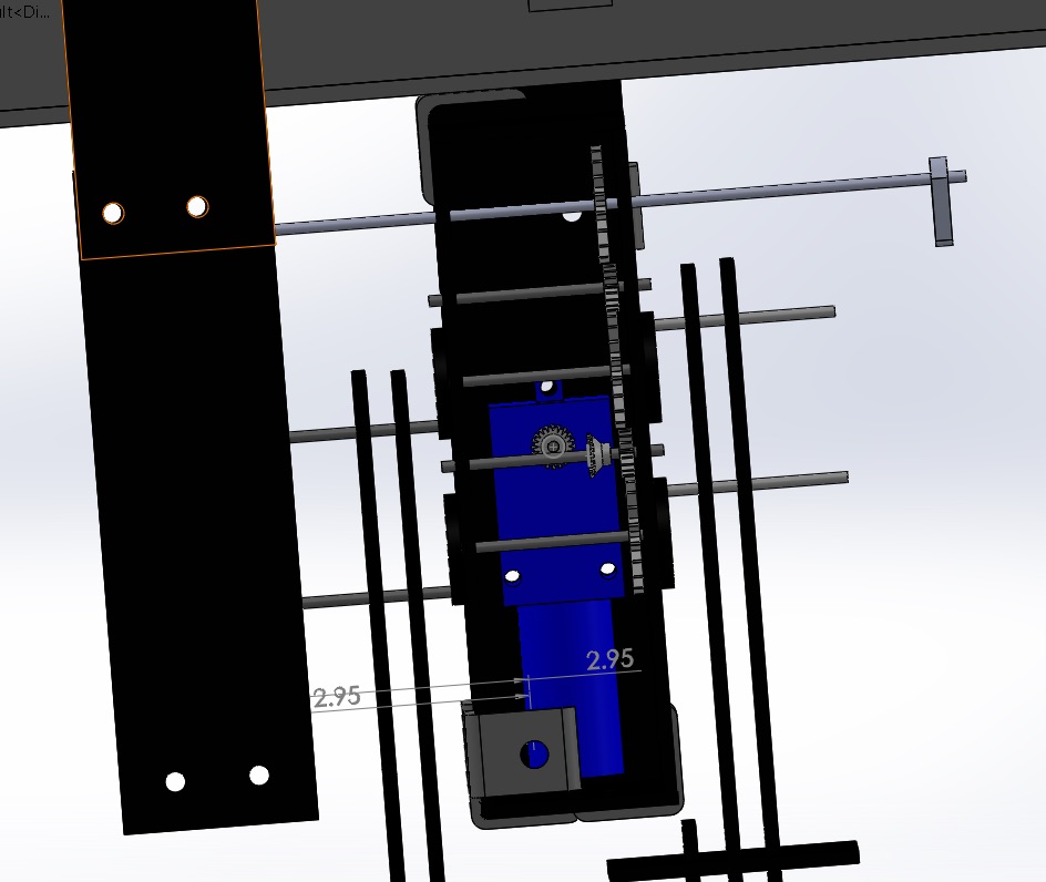
I replaced the head and the tail mechanism with a rack and pinion on a linear bearing. This mechanism requires a DC motor instead of two servos. The DC motors will send feedback from the rotary encoders to indicate how many turns and at what angle the rack positioned at. The DC motor moves the shaft back and forth to adjust the Velociraptors center of gravity. At the end of the shafts are counter weight holders that hang low to the ground to lower the center of gravity and increase balance.
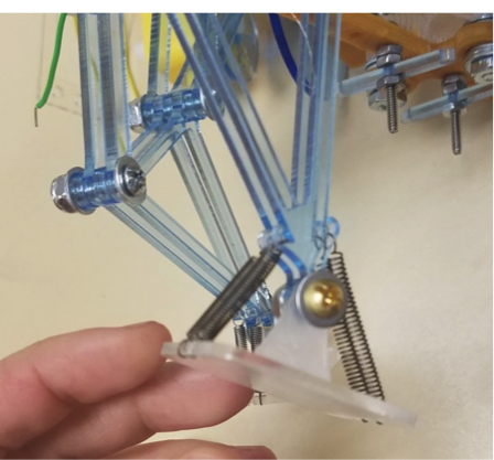
I found the foot mechanism to be somewhat successful in maintaining the stability of the velociraptor while it walks, however, the more weight I added to the velociraptor (DC motors, rack and pinion, etc.), the more resistance I required from the springs. Later I plan to double the amount of springs in the feet.
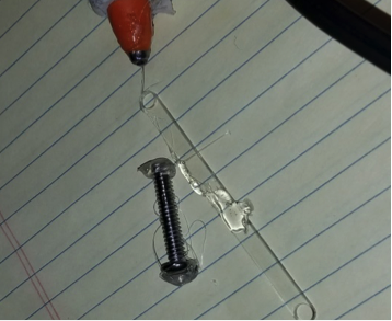
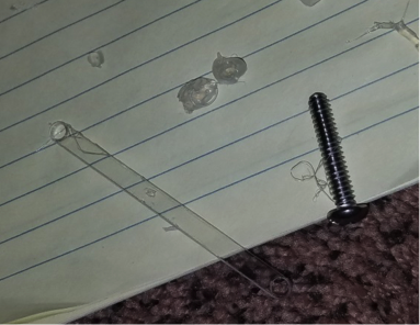
I printed some feet and ordered some rubber. I will eventually glue the rubber to the larger foot platforms and attach them to the raptor. The raptor can stand on rubber far better than it can stand on a smooth surface such as tile or plastic flooring. The velociraptor is shown slipping in the following image. He caught himself by landing on his knee.
Although I decreased the hole size for the 6-32 screw shaft to the minimum there is still some wiggle room in the legs. When You laser cut it actually cuts a little larger than expected (Contrary to 3D printing). If I could cut again I’d reduce the hole size a little more since the legs still have some wobble due to the wiggle room in the shaft holes.
I cut some squares that will eventually be used to mount the 3Dot board and the PCB.
I used hot glue in place of super glue or screws since it is easy to peel off if needed. Hot glue was surprisingly useful for temporary fastening of parts, especially parts that don’t have easy compatibility such as DC motors and Servos. Hot glue caused no damage to these parts after being peeled off. I tested this in the following before and after images.
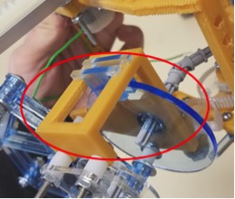
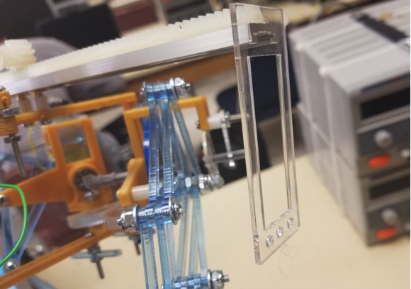
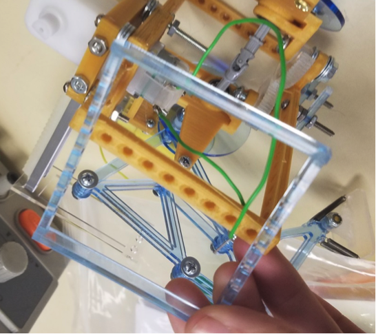
The turning mechanism was successful as can be observed from the following pictures.
The hips can be turned up to 90 degrees outward on each side. When the legs open the shaft connected to the u-joints and legs slide inward. The more the legs open the more room the shaft needs to be able to slide inward. All of this needed to be taken in to account in order to prevent interference of parts.
Conclusion
The new velociraptor is far less wobbly then the first. The hip mechanism, foot mechanism and the new head and tail mechanism work successful. The only thing I would change is the leg mechanism so that it’s sturdier and less wobbly.
https://www.arxterra.com/wp-content/uploads/2017/05/Assembly12-1-300x199-1.png144144Jesus Denriquez/wp-content/uploads/2013/04/Arxterra-Logo-340x156.pngJesus Denriquez2017-05-20 07:52:462018-03-09 08:18:58Spring 2017 Velociraptor: Final Assembly Update
The objective of this trade off study is to select an electrical device that can detect RPMs for our motors. One way RPM detection is important for our project would be our wheel slip detection.
Subsystem Relation
On the subsystem level, there are many things that we hope to accomplish with rotary encoders. We would like to detect wheel slip, wheel has lost traction or free spinning in the air, for each motor. We would also like to use the rotary encoders within differential turning and the climbing algorithm.
In order to fulfill this requirement, we researched optical shaft encoders, magnetic shaft encoders, and even considered designing a custom shaft encoder PCB.
Optical Shaft Encoder
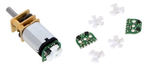
Pololu’s optical encoders are sensor boards and reflective wheels added to micro metal gear motors with extended back shafts. They have the option of a 3-tooth and a 5-tooth encoder that provides a 12 counts per revolution or 20 counts per revolution. These encoders output are direct photo-transistor outputs. [1]
Figure 1. Optical Encoder
Magnetic Shaft Encoder
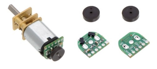
Similar to the optical encoder, Pololu’s magnetic encoders are attached to the extended shaft of an geared motor. These boards use 6-pole magnetic discs that can be used to add quadrature encoding. This board senses the rotation of the magnetic disc and provides a resolution of 12 counts per revolution of the motor shaft when counting the ends of both channels. [2]
Figure 2. Magnetic Encoder
Custom Shaft Encoder PCB
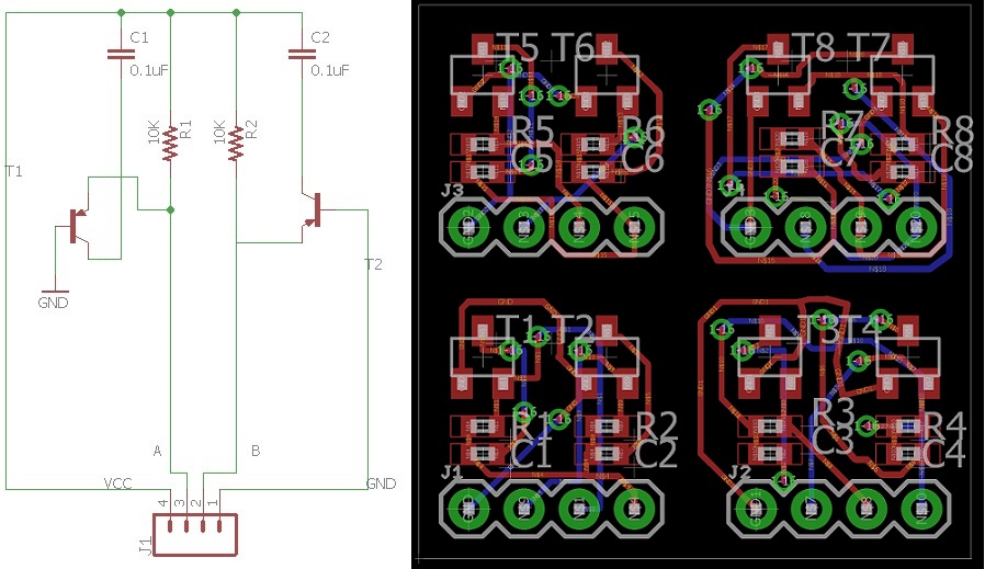
The custom shaft encoder was inspired by the magnetic shaft encoder just mentioned. The architecture is exactly like the shaft encoder. Although, after detailed research to find the exact EagleCad symbol for our hall effect sensor TLE4946-2K that the magnetic sensor uses. We discovered that the TLE4946-2K hall effect sensor can be with in TO-236-3, SC-59, SOT-23-3 packages. Digikey will send the package in SC-59. Fortunately, there are MOSFETs and Transistors that share similar packages. I choose PNP transistor that has a package of SC-59-BEC, SC59 (SOT23) Motorola, to be place holders for the hall effect sensor that we will purchase.
Figure 3. Magnetic Encoder Schematic and Layout
We were considering creating our own because we would have the ability to produce four from one square inch of PCB. The decision factor revolved around cost and time to have them implemented in our design.
Conclusion
In conclusion, we realized too late that we did not purchase the extended metal gear motors that would fit perfectly with the optical or magnetic shaft encoders. We decided to decline creating custom shaft encoders because they would be too time costly and we wanted to ensure that we had working encoders. We chose to purchase the magnetic shaft encoders instead. Although, we did not place the encoder behind the motor but inside a slit that held the motor attached to the suspension. We placed magnets on the inner wheel. As the wheel rotates the sensor should catch the change in poles from the magnet.
By: Oscar Ramirez (MST)
-Body
Edited and Approved By: Jesus Enriquez (Project Manager)
-Introduction & Conclusion
Table of Contents
Introduction
One of the requirements for our Velociraptor was giving it the ability to count the number of dots it encounters in the maze. In order to solve this issue, we came up with a creative solution which uses an LED to signal that the Velociraptor has encountered a dot.
Requirement L2-2: The Velociraptor shall be able to count the number of dots it encounters in the custom maze using an SMD LED to indicate that it counted a dot
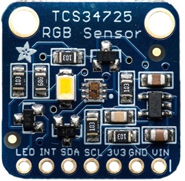
RGB Sensor
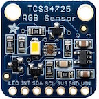
As part of our mission objective, the velociraptor must be able to detect the colored dots inside the maze that it will also be navigating. The TCS34725 color sensor does a great job of detecting a number of colors, from a long distance (about 4 inches). When the color sensor detects the dot inside the maze a led will illuminate, showing that the velociraptor has stepped over a dot. To begin, the color sensor had four pins that needed to be configured to the Arduino. The SDA and SCL pins were hooked up to analog pins A5 and A4 (SDA & SCL respectively). Then the Vcc and ground pins were connected to 3.3V and common ground inside our test circuit.
Figure 1: TCS34725 Color Sensor
Programming the RGB Sensor
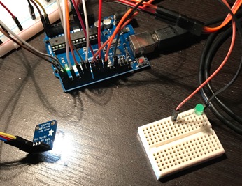
To program the TCS34725 we first needed the associated library files. Once those were downloaded inside the Arduino library we were ready to begin. I first set the designated LED pin to an output inside the setup. For this experiment I tried only detecting the color red, but also included blue and green in case the color of the dots inside the maze were to change. I created three 16-bit variables to store the data that the sensor picks up and designated them blue, red, and green. Grabbing the data the sensor was currently picking up I stored it inside these variables. These numbers can fluctuate from around 200 all the way up to 4000 per color depending on the intensity and proximity of the color i.e. the closer and clearer the color, the higher the number. While placing the sensor over the color red it does give values of about 3000 but also gives values for blue and green at about 1000. To differentiate between colors I took the average of all of the colors and then divided the particular color by the average. By comparing these values with each other it was easy to differentiate between them. On the code this was done by creating 3 different if statements and comparing the value of each color to each other. If the detected color were red then the LED would illuminate, signaling that red was detected.
Figure 2: Color sensor facing flat detecting no color (LED OFF)
Figure 3: Color sensor detecting the color red from about 4 inches (LED ON)
This method for counting dots was the simplest form we could come up with in terms of electronics and coding. One issue that we came across was that we did not take into account how long to keep the LED on after encountering a dot. To solve this issue, it is recommended to work with sending telemetry back through the arxterra app to let the user know when a dot has been counted.
https://www.arxterra.com/wp-content/uploads/2017/05/Picture1-1.jpg144144Jesus Denriquez/wp-content/uploads/2013/04/Arxterra-Logo-340x156.pngJesus Denriquez2017-05-20 07:39:262018-03-09 08:18:58Spring 2017 Velociraptor: Configuring the TCS34725 Color Sensor
The mini pathfinder will utilize one small encapsulated 5V 200mA solar cell. The reason for this is because it requires less cells to come up with the voltage and current required to charge the battery than if using the normal type cells, meaning less real estate on the small rover.
Results
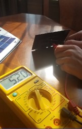
The size of the solar panel for the Mini Pathfinder should be 122x52mm, but the size of the one on hand is 120x70mm. This cell will be connected through the usb port to recharge the battery on the 3Dot board.The measured voltage was 5.2V
Figure 1. Solar Panel Voltage
Conclusion
The voltage of this solar panel is enough to charge the 3Dot board through the usb port during operation. The next step will be to determine if the solar panel can output enough current.
https://www.arxterra.com/wp-content/uploads/2017/05/sojourner_solar_panel.jpg144144John Her/wp-content/uploads/2013/04/Arxterra-Logo-340x156.pngJohn Her2017-05-20 07:35:252018-03-09 07:35:24Spring 2017 Mini Pathfinder Solar Cell Voltage Test
The BiPed team was assigned the task of designing a 7th generation bipedal toy robot utilizing a 3Dot board. The robot was to use D.C. motors as the main driver for walking motion instead of the more frequently used servo based motion. Project Biped was to be able to demonstrate static walking and should be able to demonstrate the ability to dynamic walk and turn. Our project overall was to cost lest than $200.00 as well as be completed and ready to participate in the end of semester game on May 15th, 2017.
Mission Profile
The Biped shall be able to participate in the end of semester “Pacman” game where the goal is to navigate a maze while being remotely controlled. The velociraptor acts as the ghosts and attempts to catch up to the biped. If the biped is caught, then the velociraptor wins. There are also red colored dots placed around the maze that will count as points once a robot walks over it. The robot will then count the dot and continue on with the game. The time limit of the game lasts up to a maximum of 30 minutes. Viewing of the game will be provided by the spiderbot which will be hanging above the maze and relaying live video feed through the arxterra control panel. The game rules can be referred to here.
Project Features
Ankle Turning Servos
One of the main focus and key features of our robot is that we will use servos in the ankle to turn the robot. Traditionally when turning, you would change the speed at which the individual legs move reference to each other. You could have one leg moving while he other remains stationary or you can even have them rotate opposite of each other. For our design, none of the would work considering that we were using just one D.C. motor to power everything. Since we had one motor that rotate both legs simultaneously, we thought to get one leg off the ground and then to turn it from there. This proved to be an acceptable solution and perfect feature for our robot.
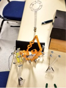
Tilt Box For Counterweight
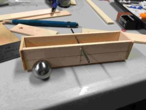
The other challenge for us was to be able to shift the center of mass of the robot to each leg as it would walk. Whenever a leg would lift up, the robot would immediately tilt over and fall. To attach this issue, we copied the idea from a Theo-Jansen video that was seen on the internet. The idea was to have a ball, or some sort of smooth weighted object move back and forth from side to side. The weighted object in question would obviously need to have weighed a majority of the entire systems weight to be able shift the center of mass, so mass allocations was a concern but we fell within requirements. In our design we incorporated a wooden box that would look like arms, and had a cam attached right beneath it to tilt the box back and forth effectively moving the ball back and forth.
This blog post goes more in depth with how the tilt box is essential to the robot.
The robot will be able to be controlled using the arxterra phone application or through a computer using the arxterra control panel. Due to the mission profile stating that we will be viewing game through a video, we needed to make the robot able to be controlled remotely. For our design we included a bluetooth module on the Arduino and from there was able to remotely control the BiPed. (3Dots were the planned component but through certain situations we were not able to use them and resorted to using an Arduino)
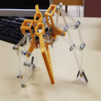
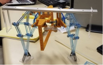
Simplistic/Straight Leg Design
For our robot we decided to go with a straight legged design instead of the more popular approach of using linkages. A few reasons for this is that we wanted to keep the robot as light as possible and as simple as possible. Adding linkages means more parts and more connections that need to be held together and ultimately adds more weight. More connections means more fasteners (or something of the sort) and the linkages would add material stress into consideration in more places than we intended. Keeping a straight leg would limit our focus on stress to only a few areas. We also essentially wanted to start over from scratch considering the last generation did not work with a D.C. motor source driven motion. If we were able to get it to walk, turn and succeed in all its functions, then the next class would be able to improve on it even more. It would be a lot more difficult for a class to try and find out what was wrong with the last one and improve it, than get a perfectly functioning one and improve it.
System Design
System Block Diagram
The system Block Diagram shows the inputs and outputs of our robotic system. From the input side we have the HM-10 Bluetooth module that receives data from the Arxterra application and an Adafruit color sensor that detects when the Biped is standing on a red surface. For outputs we have two servos and a DC motor that enable the robot to walk and turn. Lastly we have 3 LEDs to provide a visual effect. Two will be the “eyes” of the robot and one will be toggled on and off based on the color sensor inputs.
Subsystem Design
Experimental Results
We were able to test out and experiment on all the key components of our robot. The main concerns are all listed in this section of the blog post.
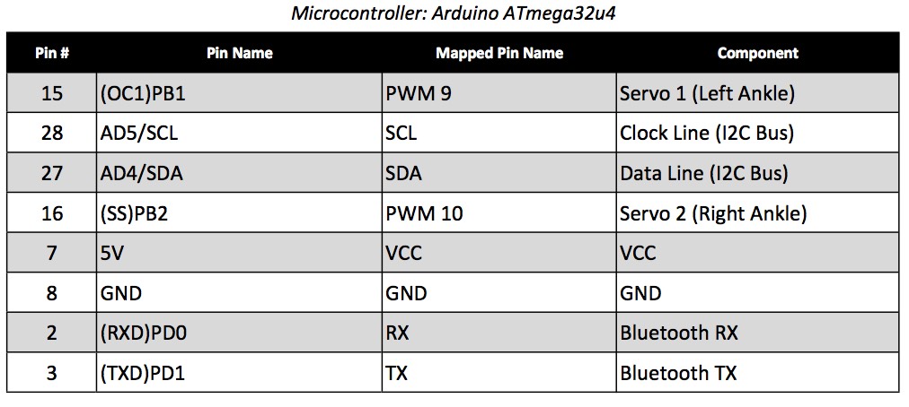
The BiPed utilizes a total of 8 pins from the Arduino microcontroller. The left and right ankle servos are controlled by PWM pins 9 and 10 while the DC motor and color sensor are controlled by the I2C lines. Data will be transmitted through the Tx and Rx lines that are directly connected to the HM-10 Bluetooth module. All of the connected devices run off of the supplied 5V.
Mission Command and Control
Updated Software Block Diagram
The BiPed software contains six different subroutines. Five subroutines control the robots movements and one controls the color sensor and LED. The software begins by first decoding incoming data packets, then each subroutine is called based on the decoded command in the commandHandler
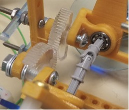
Some of the main components to the robot would be the Pololu 200:1 D.C. motor. We chose this one specifically because it had high torque and would be able to move the robot even with all the weight we were placing on it. Further more, we only used one and that helped a lot with our mass allocations. There are other components such as HXT900 micro servos and a RGB color sensor. Additional information on the components can be found here.
Firmware
All of the code and firmware that was used to control the walking, turning, and color sensor can be found here.
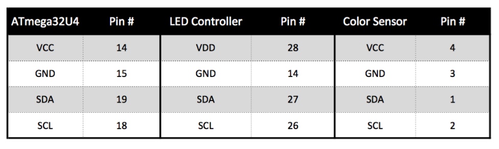
We designed our PCB to be able to function modularly from the rest of the system. In short, the robot itself can still be able to perform its main function of walking and turning without it. The main purpose for the PCB was to be able to participate in the game. For that end, we needed the robot to be able to detect dots and to light up LEDs in accordance to those dots. Initially in our first design we had the PCB with many more functions. It had two more servos connected to it to serve as a way to shift the center of mass. Now that we are using a tilting box with moving ball bearings, that is no longer needed. It also adds to the simplicity of the design and allows us to keep everything as small and light weight as possible. Now that we have two less servos to deal with, it leaves more room for us on our mass allocations. The blog post above can provide more detail into the PCB.
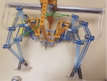
The above blog post is a show of one of the initial designs that we had previously had in mind. It again utilizes the straight leg, minimal linkage design. After progressing past this one we were able to look back on it and in retrospect really see where most of the flaws were coming from. Some of the key issues are as follows:
Off-centered weight (D.C. motor sticking out of the body to the right)
Unreliable pulley system
Unacceptable leg design (overlapping)
No center of gravity shift or consideration.
Incorrect use of gear ratios (not specified in the blog post)
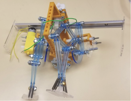
From these five lessons as well as others, we were able to come up with a better design and improve off the last one. The main difference with the newer design as opposed to the one before is that the dc motor is not centered in the middle. This makes it easier for balancing and the shifting of the center of mass. Now that most of the components are in the middle, the weighted ball can move from side to side at equal lengths. We also moved away from the pulley system completely. The blog post below as well as the images may provide better insight into the actual physical design.
We had written up our verification and validation in accordance to the new format which we had linked in the link below. The verification matrix is also included within the test plan and it documents all of the requirements that we were aiming to hit and those of which that we had not.
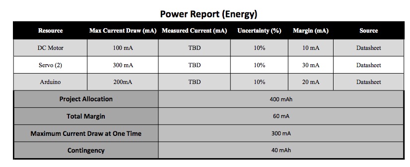
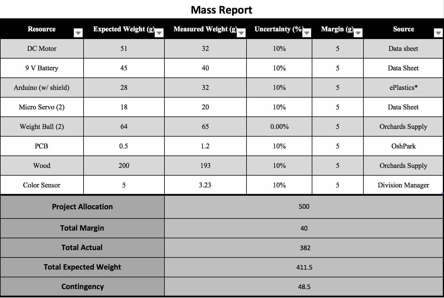
The Table above shows the maximum current the robot can draw at one particular time. This would mean both servos and the DC motor are at full power. The max current draw is 600 mA with a 60 mA margin. Our battery can only supply around 650 mA at a given time so this means our contingency is actually negative. While this may seem bad, its an impossible scenario because our robot will never be running all 3 actuators at one time.
This table shows the max current of each actuator with the total capacity of our battery. The goal here is to ensure the battery has enough energy to power the Biped for at least 30 minutes. Since the robot will only be using one actuator at a time, the worst case scenario would be the Arduino (200 mA) and the DC motor (100 mA) running at full power. At 300 mA our battery is rated with a total capacity of 400 mAh. This means our robot will be able to supply power much longer than our desired minimum.
Mass Allocation
Cost Report
Receipt
Vendor
Item
Unit Price
Quantity
Total Cost (Including Shipping)
Purchased By
1
Pololu
200:1 Plastic Gear Motor
5.75
1
23.70
Abraham Falcon
2
Adafruit
RGB Color Sensor w/ IR Filter and White LED – TCS34725 PID: 1334
7.95
1
23.94
Abraham Falcon
3
Mouser
1 K Ohm Thick Film Resistor
0.10
3
0.30
Abraham Falcon
3
Mouser
Standard LEDs (Red Diffused)
0.360
2
0.72
Abraham Falcon
3
Mouser
Standard LEDs (Green Diffused)
0.360
1
0.36
Abraham Falcon
3
Mouser
10 uF Multilayer Ceramic Capacitors
0.60
1
0.60
Abraham Falcon
3
Mouser
10 K Ohm Thick Film Resistor
0.10
3
0.30
Abraham Falcon
3
Mouser
Semiconductors I2C Bus LED / LED Display Drivers
2.31
1
2.31
Abraham Falcon
3
Mouser
Molex KK 100 Hdr Assy Bkwy / Headers and Wire Housing
0.27
2
0.54
Abraham Falcon
3
Mouser
Molex BREAKAWAY HDR VERT 2 / Headers and Wire Housing
0.16
3
0.48
Abraham Falcon
3
Mouser
(Shipping+Tax)
19.83
1
19.83
Abraham Falcon
4
Home Depot
Acrylic Sheet
10.27
1
11.17
Alexander Clavel
5
Staples
Staedtler Math Zip
4.99
1
4.99
Alexander Clavel
5
Staples
Loctite Liquid Super Glue
5.99
1
5.99
Alexander Clavel
6
Amazon
120 Pc RC Parts Lot (Plastic Gears, Pulley…)
13.95
1
19.94
Alexander Clavel
7
Amazon
Geebot Pulley Combination Package
9.99
1
9.99
Alexander Clavel
7
Amazon
Ajax Scientific Plastic Loose Pulley, 50 mm Diameter
8.52
1
8.52
Alexander Clavel
7
Amazon
Ajax Scientific Plastic Loose Pulley, 25 mm Diameter
8.21
1
8.21
Alexander Clavel
7
Amazon
(Shipping +Tax)
7.81
1
7.81
Alexander Clavel
8
Amazon
2 of HXT900 9g Micro Servo
6.49
1
12.98
Alexander Clavel
9
Amazon
120 Pc RC Parts Lot (Plastic Gears, Pulley…)
13.95
1
13.95
Alexander Clavel
9
Amazon
10 PCs 2mm Dia 250mm Length Stainless Steel Rod Shaft
7.51
1
7.51
Alexander Clavel
Total:
184.14
Budget Allocation:
200.00
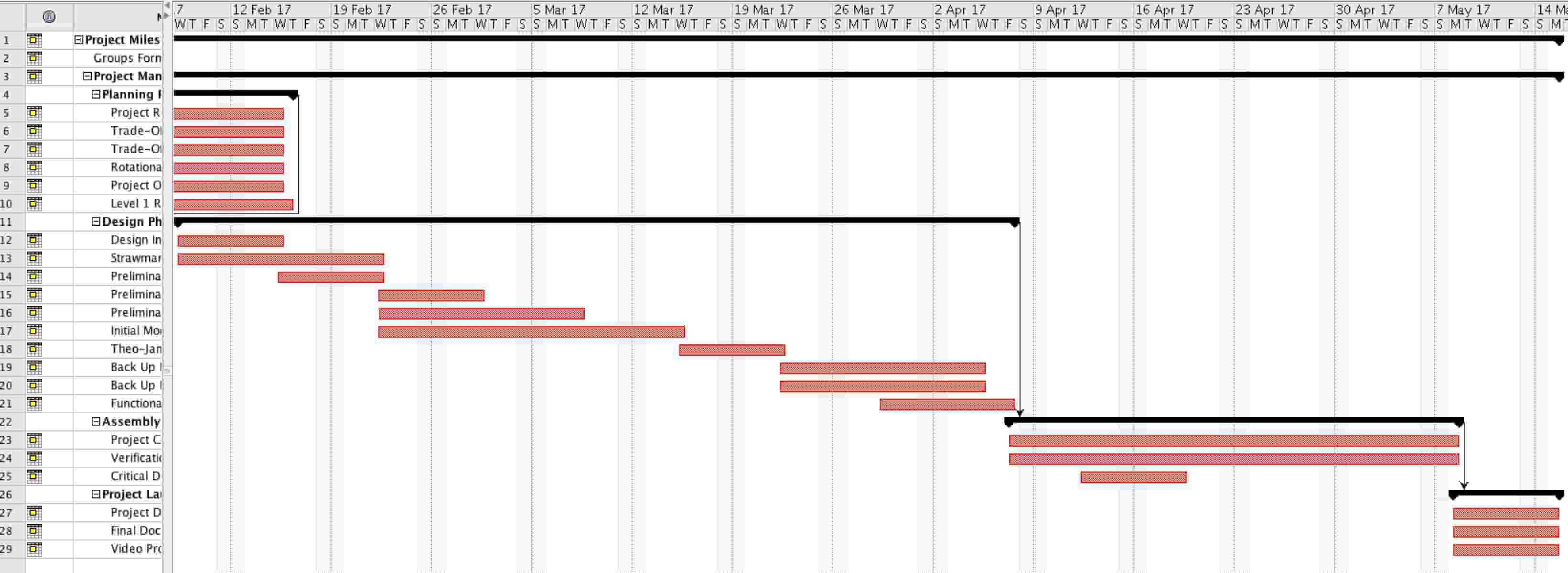
Updated Schedule
Top Level
Subsystem
Much of the top level schedule had remained the same mostly because most of the top level tasks had been completed. In the subsystem schedule you can see that some of the tasks mainly in electronics and control and in manufacturing had been pushed back some. This was mostly due to manufacturing’s inability to be able to produce and assemble a working prototype.
Burndown and Percent Complete
The project ended up being rushed at the end but we were able to finish on time. There were many bumps along the road like components not working, or accidental drops that hindered the progress of the project as a whole but in the end we were able to finish everything on time.
Summary / Concluding Thoughts
Results
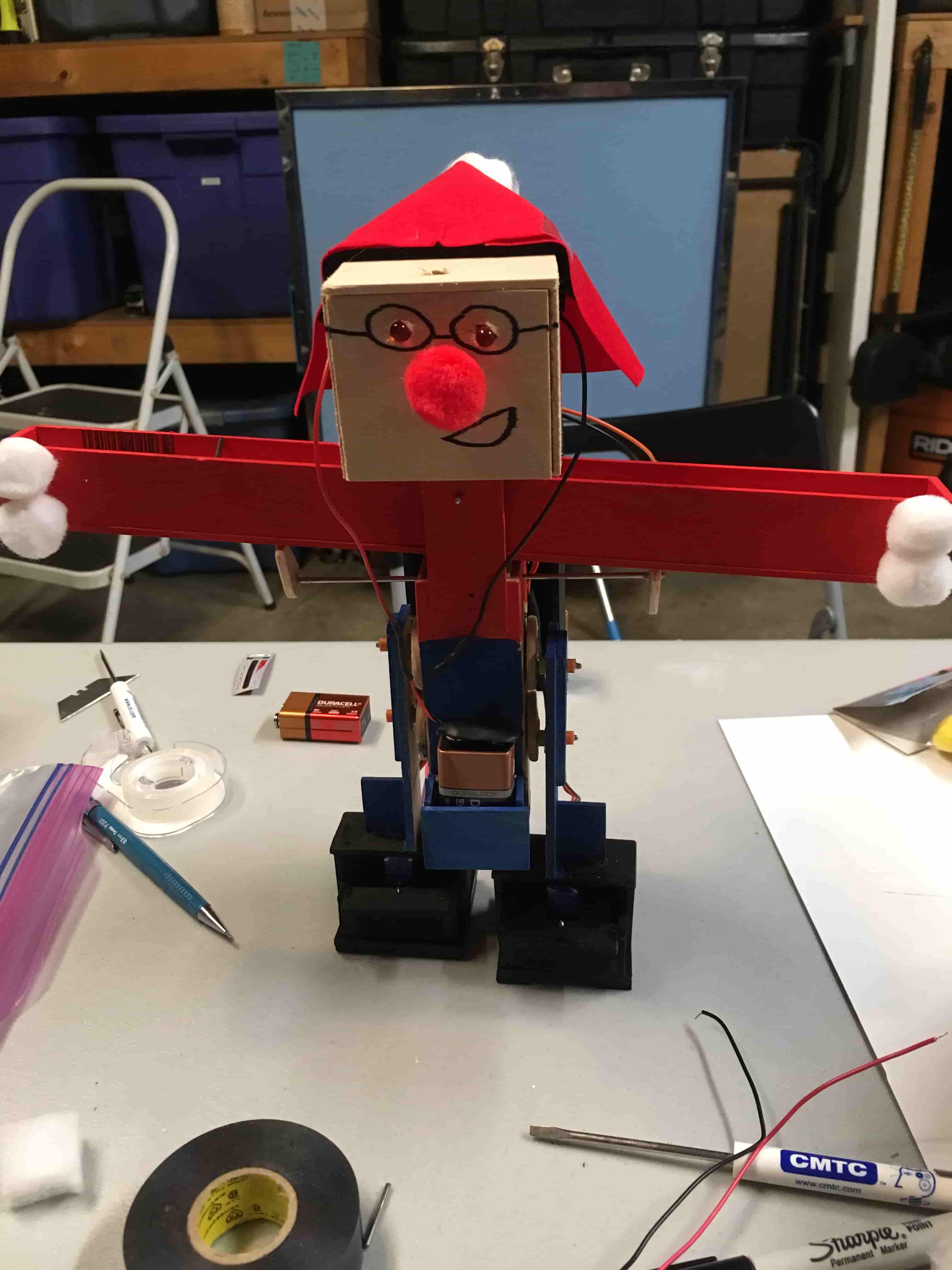
In the end the project was completed on time. We were able to create a statically walking BiPed that was bluetooth remotely controlled and was able to turn up to 180 degrees. We stayed within budget costs and weight limits that were set. The only issue was that nearing the demonstration date, the BiPed was dropped and the timing for the tilt box was thrown off and ultimately threw off the entire walking motion. We continuously tried to solve the problem before demonstrating it, but we ended up running out of time. Although it did not walk on the actual day of the demonstration, we are happy that we were able to get a fully functional system running and working exactly as we had intended it to. We can strongly say that this is a strong base for the next class to try and improve on it especially because it is a system that works.
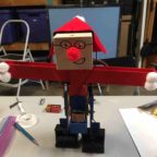
We also ended up running out of time because we had planned to laser cut the entire body our of plastic and to make it look sleek and nice. Due to being rushed and having limited time for testing, this was not able to happen. We had, at the end, printed out the head unit, body, and legs, but had not completed the tilting box, cams for the box, and the servo brackets to hold the feet. Ultimately it ended up looking like an evil Santa Claus due to the request of the customer wanting it to be more “toy-like” and fun looking.
The two different videos below show the BiPed in 2 different stages of its development. The first video shows the BiPEd with minimal weight on it and purely tests the functionality of it’s ability to turn and walk forward. The second video is in the final stages of its production and has (for all intents and purposes) the amount of weight that it would normally carry. In this test we decided to test out one of the requirements that it be bluetooth controlled from a distance of 5 feet. Jacob in the background is controlling the BiPed as it walks forward from a measure distance of 5 feet. All of this shows the success of the project in itself.
Video 1
Video 2
Lessons Learned/Future Suggestions
******THIS IS A MECHANICALLY CHALLENGING PROJECT*******
When you look at this project as a whole, we are studying to become electrical engineers and in all honesty do not focus too much on the physical aspects of a system. Granted, we have our basic physics courses and knowledge, but we are not experts on the mechanics of robots. That being said, manufacturing division must be a huge focus of the project managers from the beginning of the semester. From the very beginning you need to focus on getting a system that is structurally sound and something that works. If you cannot do that then, it does not matter how amazing of an electrical engineer you or any of your teammates are. If you cannot produce a testable system that is structurally sound, you will not be able to progress at all. The issue that I ran into with my project group was that at the time that my systems and electronics engineers were ready to test, my manufacturing had not yet produced a testable model. This was where the brunt of our time was spent. More time should have gone into studying and researching how to actually design the physical aspects of the robot. The assumption was that it was going to be quick and easy was one of our biggest downfalls.
The other very destructive aspect of our project process was that we spent much too long in the “creative” aspect of our design. There were many times where we keep throwing out ideas that we thought would be “cool” or innovative where instead we should have stuck to one idea, one solution and worked on it from there. There were three specific times where we worked an initial design and then from there, we thought of “a better way to do it”. We then scrapped the first option and completely started anew with the next one. This happened 3 times and it pushed us far back past our schedule than I had originally intended. This leads into the role as the project manager. Sometimes you just have to push your engineers. You cannot be worried about them liking you and you cannot have things be personal between you and your team. The project is a team effort and everyone has to do their part. If someone is slacking you have to be able to tell them in a firm manner that they are not performing the way that they should be. I made the mistake of trying to be too nice. I feel that in doing that, it gave certain individuals the idea that they were able to push due dates back on me. The difficult part that you will have to figure out on your own is being able to discern that sensitive line between destroying their motivation to do any work, and the firm hand that will keep them doing their job.
Lastly, when it really comes down to it and there is no other option, the project manager must step in to get the job done. There may be a time where a certain division is not doing their job and no matter what you do, they just do not improve or produce acceptable work. It is at that time that you must step in and just complete the work yourself. Whether you do that by getting help from the other division members/manager, or you step in to do the work yourself. As the project manager, results and ultimately mission success falls completely on you. Yes you may find a fault in one of your divisions, and yes it may be clear where things went wrong, but you are the one who’s job it is it make sure those don’t happen. I found myself in the situation where I waited to long to do just that. I could not wait any longer and I had to step in to build the physical aspect of the robot myself. It was done with just enough time, but it was a stressful and extremely arduous process. If I was able to identify the problem sooner and stepped in sooner, we may have been able to get in a few more tests than we had actually completed. We may have been able to make the robot more durable and last longer. The point is that you are ultimate quality control and the performance and quality of the project rests on you.
In summary:
Focus on the physical robot mechanics and structural aspects
Do the research, and not just when you think it is enough (Continually question your design for flaws)
Do not jump around on options. Once you have picked a design, stick with it until you have exhausted all solutions
Push project members to do their job
Quality control the work that is being done by your members
BE PREPARED TO STEP IN AND DO ANY JOB THAT IS REQUIRED
https://www.arxterra.com/wp-content/uploads/2017/05/51652580719__7020D665-4231-4738-9DC2-6E999B20B992-min-2-e1495256688216.jpg144144Alexander Clavel/wp-content/uploads/2013/04/Arxterra-Logo-340x156.pngAlexander Clavel2017-05-20 07:22:412018-03-08 22:16:12Spring 2017 BiPed – Final Blog Post
By: Oscar Ramirez (MST)
-Body Edited and Approved By: Jesus Enriquez (Project Manager)
– Introduction & Conclusion
Table of Contents
Introduction
One of the challenges that we had to come up with was coming up with creative way to get the Velociraptor to perform a static walk. Adding to this challenge we needed to control and implement this static walk through the Arxterra app. With the help of our MST engineer, our team was able to come up with a way to control the DC motors that drive the Velociraptor through a “Move” command on the Arxterra app.
Requirement L2-7: The Velociraptor shall be able to perform a static walk Requirement L2-5: The Velociraptor shall use the Arxterra Android or iPhone Application and/or control panel to control the Velociraptor
Testing the “Move” Command
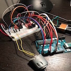
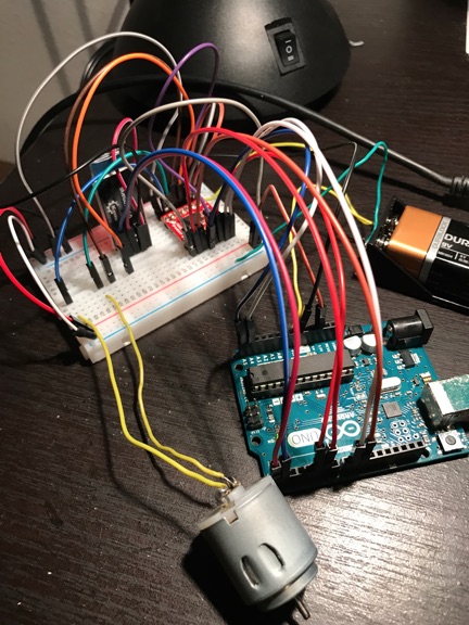
One of the first telemetry commands that we implemented for Velociraptor was the “MOVE” command. The MOVE command controls both the speed and direction of DC Motors A or B on the 3DoT Board. The 3DoT Board uses the TB6612FNG motor driver that can drive two DC motors and control their speed, direction, and even brake. The braking feature can be very useful, especially considering the balance issues with biped robots. The movement speed of the motor is also important to our design since we are using the Theo Jansen walking mechanism that requires a fair amount of control to keep the robot balanced. As far as the direction, it will not be used for our design since it is not practical for the DC motors to go in opposite direction. After testing the MOVE command on CoolTerm and verifying that the board received the command, I moved on to physically testing the move command by setting up the HM-10 Bluetooth sensor and the TB6612FNG on a breadboard. For prototyping purposes I used the Arduino UNO as the micro-controller and used a 9V battery as the main power source for the motor and Arduino UNO.
Figure 1: Arduino UNO breadboard setup with the HM-10 and TB6612FNG
Once synching to the HM-10 with the Arxterra App I used the Joystick layout to send a move forward command to the Bluetooth sensor that then relayed that command to the MCU and back out through the PWM pin and analog pin. Once confirming that the MOVE command worked through simulation and testing we were ready to proceed to the next step in our design.
Figure 2: Sending a “move forward” command on the Arxterra app
Conclusion
Through testing, we were able to successfully send bluetooth telemetry commands through the Arxterra app. It was convenient for our design in that we were able to control the speed of the DC motors which is necessary for a design like the Velociraptor. It is recommended that this be one of the first tests or tasks to complete when doing the velociraptor project since there will need to be a ton of testing for moving the legs/walking which is the most critical to making successful project work.
https://www.arxterra.com/wp-content/uploads/2017/05/hm-1.jpg144144Jesus Denriquez/wp-content/uploads/2013/04/Arxterra-Logo-340x156.pngJesus Denriquez2017-05-20 06:59:562018-03-09 08:18:58Spring 2017 Velociraptor: Configuring the HM-10 to Work With the TB6612FNG