Spring 2016 RoFi: Servo Driver, Accelerometer and Gyroscope Testing
Christopher Andelin (Project Manager)
Mario Ramirez (Systems Engineer)
Qui Du (Manufacturing Engineer)
Andrew Laqui (Electronics and Controls Engineer)
Henry Ruff (Electronics and Controls Engineer)
Servo Driver Testing
Andrew Laqui (Electronics and Controls Engineer)
Henry Ruff (Electronics and Controls Engineer)
Servo Driver Part Number: PCA9685
Link to Adafruit Servo Driver “Using the Adafruit Library” page https://learn.adafruit.com/16-channel-pwm-servo-driver/using-the-adafruit-library

Figure 1: Servo Driver Fritzing Diagram

Figure 2: Servo Driver Fritzing Schematic
Link to Adafruit library for Fritzing https://github.com/adafruit/Fritzing-Library
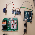
A Basic Stamp HomeWork Board with a built in 5V regulator was used to regulate the voltage from a 9V battery to power the servo. When the old Detrum UBEC regulator was used, the Tower Pro SG90 servo only made a buzzing noise; it was unresponsive. When we switched to the Basic Stamp HomeWork Board, the servo swept back and forth as it should.

Figure 3: Servo Driver Testing
The code was modified to only run the first servo (servonum = 0) rather than incrementing through 8 servos.
The code was modified from the Adafruit Servo Driver Library for Arduino Uno to match the pulse width of the Tower Pro SG90 servo.
Link to Tower Pro SG90 specifications http://www.servodatabase.com/servo/towerpro/sg90
#define SERVOMIN 500 // this is the 'minimum' pulse length count (out of 4096)
// Original value was 150. Value of SG90 is 500
#define SERVOMAX 2400 // this is the 'maximum' pulse length count (out of 4096)
// Original value was 600. Value of SG90 is 2400
Link to Adafruit Servo Driver “Hooking It Up” page https://learn.adafruit.com/16-channel-pwm-servo-driver/hooking-it-up
According to the “Hooking It Up” page, an electrolytic capacitor is added to handle quick changes in voltage. Since RoFi will be using 12 servos, a 1200 µF capacitor will be used.
At the moment, the servo driver has the pins that connect the GND, VCC, SCL, and SDA to the Arduino Uno soldered to the top of the board. These will have to be unsoldered and soldered again with the pins facing the bottom of the board in order to plug the servo driver directly into RoFi’s new PCB. If the pins are left the way they are, wires will be needed to jump the pins to the PCB.
Accelerometer and Gyroscope Testing
Andrew Laqui (Electronics and Controls Engineer)
Henry Ruff (Electronics and Controls Engineer)
Link to MPU-6050 test code http://playground.arduino.cc/Main/MPU-6050

Figure 4: Accelerometer and Gyroscope Fritzing Diagram

Figure 5: Accelerometer and Gyroscope Fritzing Schematic
Link to MPU-6050 for Fritzing http://fritzing.org/projects/mpu-6050-board-gy-521-acelerometro-y-giroscopio
Once the MPU-6050 was connected according to the Figure 4 fritzing diagram and the code was uploaded to the Arduino Uno, the Arduino began displaying values for acceleration and tilt in the x, y, and z directions and temperature.

Figure 6: Accelerometer and Gyroscope Testing