Spring 2018: Testing Design Sketches
Written By: Miguel Gonzalez (Project Manager and Manufacturing Engineer)
Approved By: Miguel Garcia (Quality Assurance)
Table of Contents
Related Requirements
Level 1 Requirements
L1-3: Micro FOBO will have 2 legs.
L1-4: Micro FOBO will be a toy robot based on the design of the FOBO by Jonathan Dowdall.
L1-8: Micro FOBO’s part components will be 3D printed using the material carbon fiber PLA.
L1-11: Micro FOBO shall be 60% or less of the overall size of Jonathan Dowdall’s FOBO
Level 2 Requirements
L2-2: Micro FOBO dimensions will need to be small enough to fit in a 4in by 4in box for maze purposes.
L2-3: Micro FOBO will use SG90 micro servos.
Customer Requirements
C-03: The robot will be designed to be a toy for people ages 8+.
C-04: In order to minimize manufacturing cost, and packaging cost the robot shall be able to be constructed from sub assemblies within 10 minutes.
Before CAD
One of the first things we did when verifying our sketches was produced a copy of the original FOBO from www.projectbiped.com this would help in determining correct aspect ratios for the creation of the Micro FOBO. Using parts from previous semesters we managed to get all the necessary components to produce the FOBO. We 3D printed the parts for FOBO and assembled it all within the first three weeks of the semester.
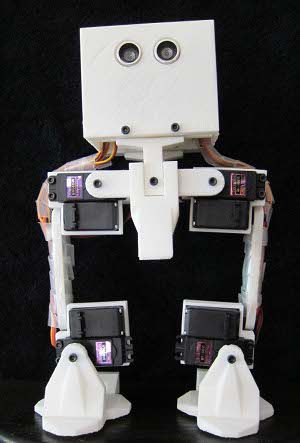
Fig.1 Original FOBO Source: projectbiped.com
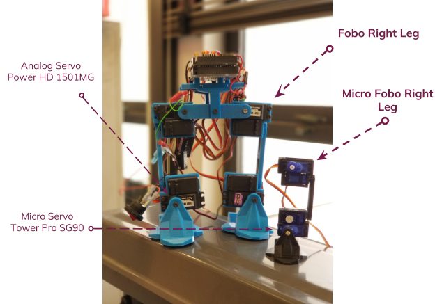
Fig.2 Printed FOBO
By using the printed out FOBO I was able to measure the individual parts of the robot and produce a scaled down version of each part. It mainly relied on using ratios of the larger servos compared to the micro servos our group planned on using. Figure 2 is an image that was taken after the testing of the micro FOBO parts but is a good illustration of the size comparison between the original FOBO (in blue) and the Micro FOBO (in black).
Creating the 3D Models
After creating the Initial Design Drawings on paper I made sure to 3D model the parts on Solid Works and test how the parts fitted together. Typically we can verify how the parts work together by using Solid Works Assembly and verifying the dimensions allow the parts to fit onto the micro servos and with one another. Of course, all parts first needed to be designed before we can verify part compatibility this also included designing the micro servos, ultrasonic sensor, and custom PCB. Below you will find 3D models of parts and components that were designed in Solid Works CAD.
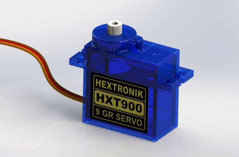
Fig.3 3D Model of Micro Servos
Once all the parts were 3D modeled the first compatibility test on the parts was conducted by assembling all parts together using Solid Works. This process involved virtually assembling the Micro FOBO and verifying that all parts fit together properly and that all mounting holes aligned with each other.
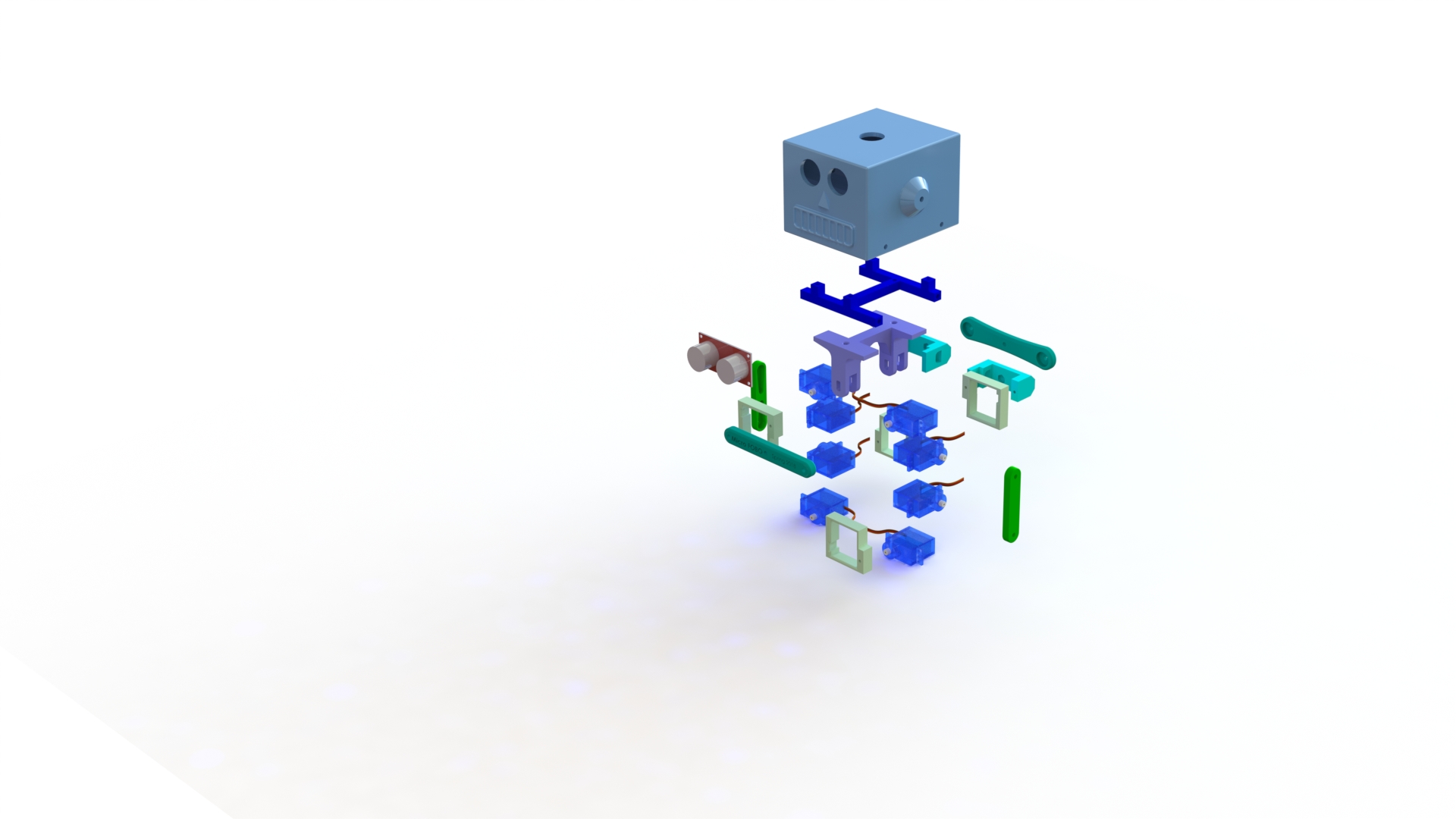
Fig.4 Micro FOBO Exploded Assembly
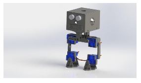
Fig.5 Micro FOBO Full Assembly
Testing the 3D Models
The last thing to do was to 3D print a prototype of the Micro FOBO and verify the results obtained from the assembly. Most parts that were printed out needed no revisions. Only the servo band and servo bracket required revisions. These parts typically required revising the mounting holes for the micro servos and slightly increasing the holes where the wires fitted through. Once the changes were applied to the model the parts were 3D printed again and verified that the issues no longer remained. We tested all designed parts by assembling a full-scale working prototype as shown below.
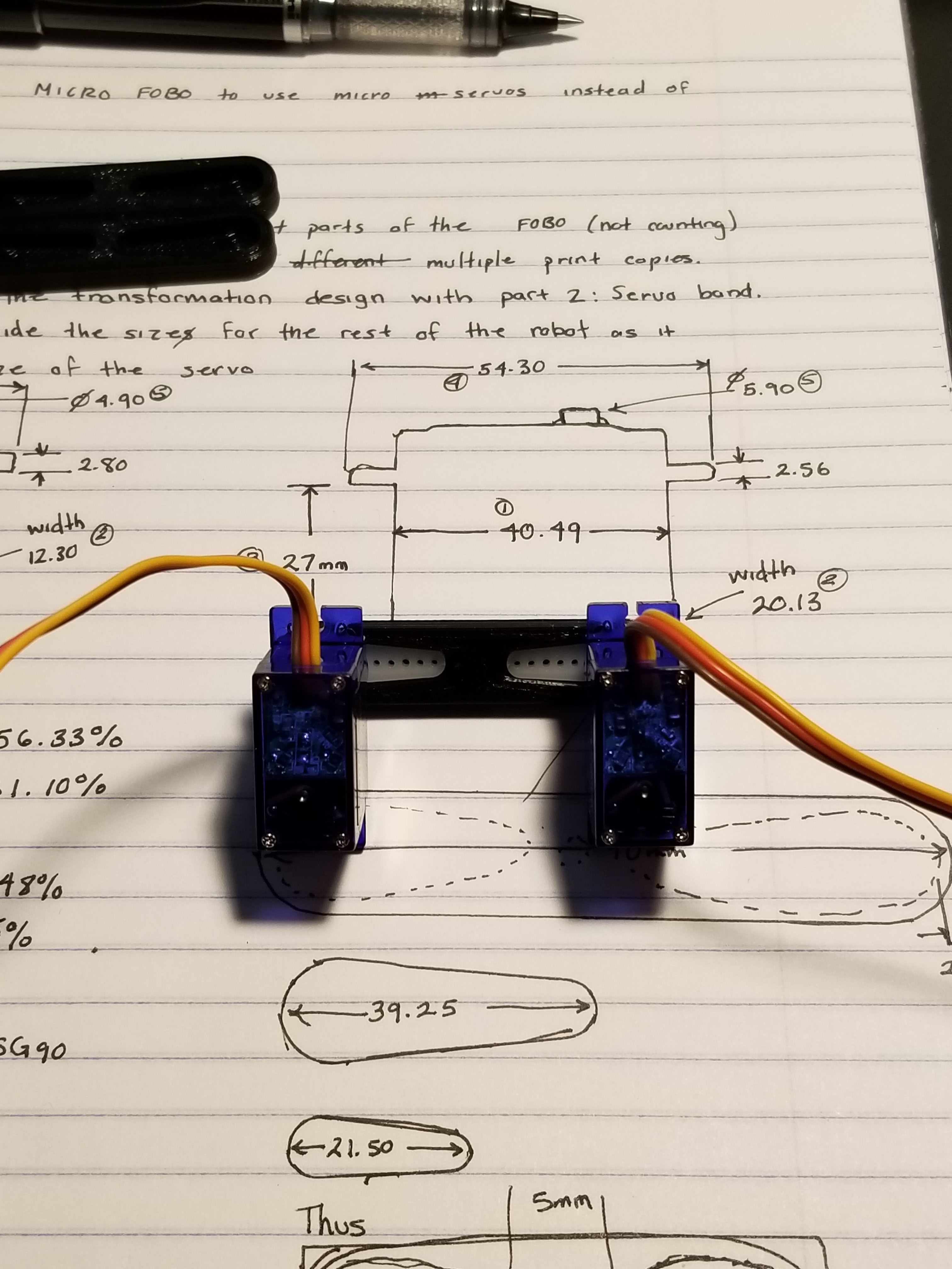
Fig.6 Part Verification
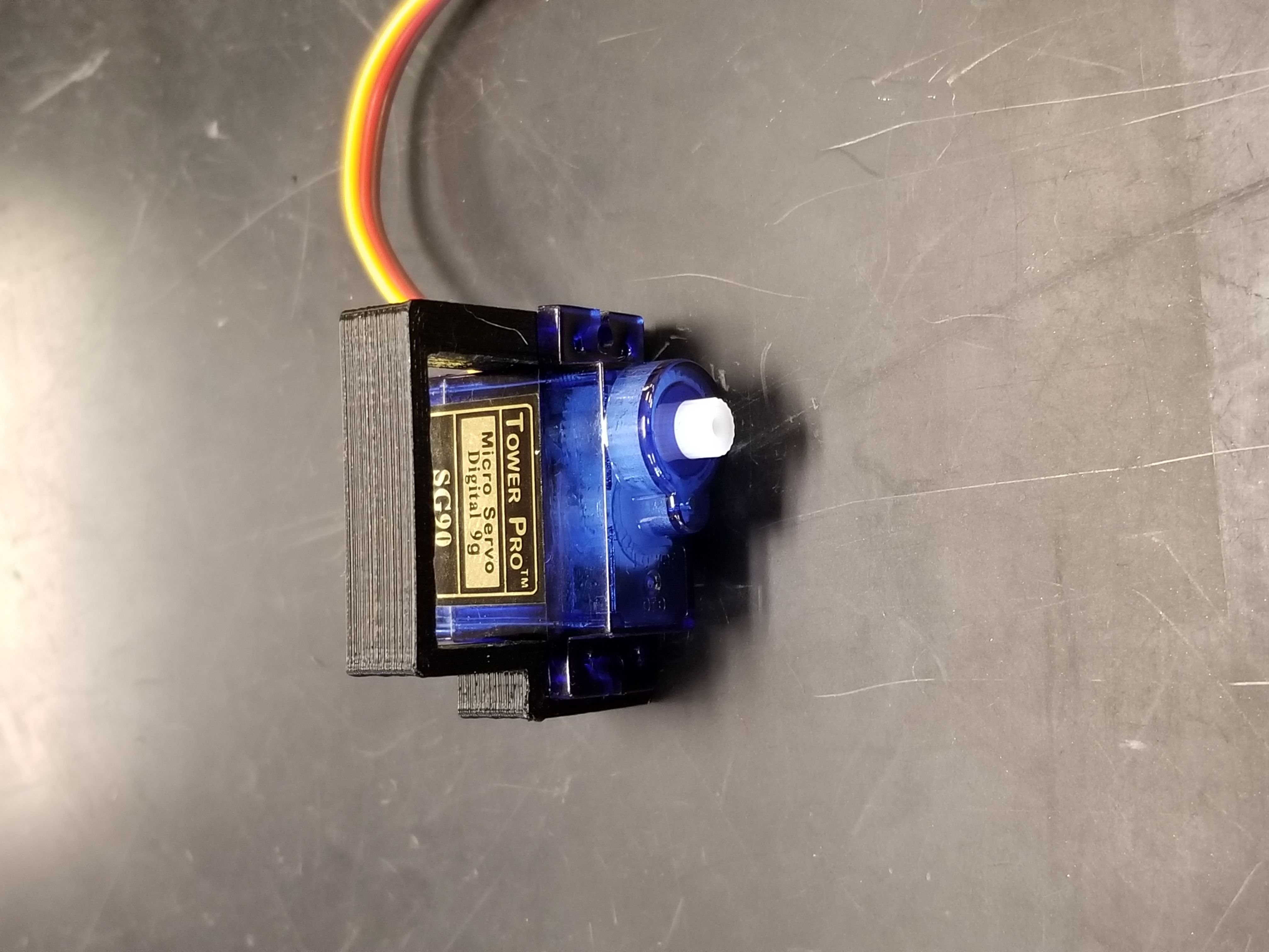
Fig.7 Testing Servo Fitting
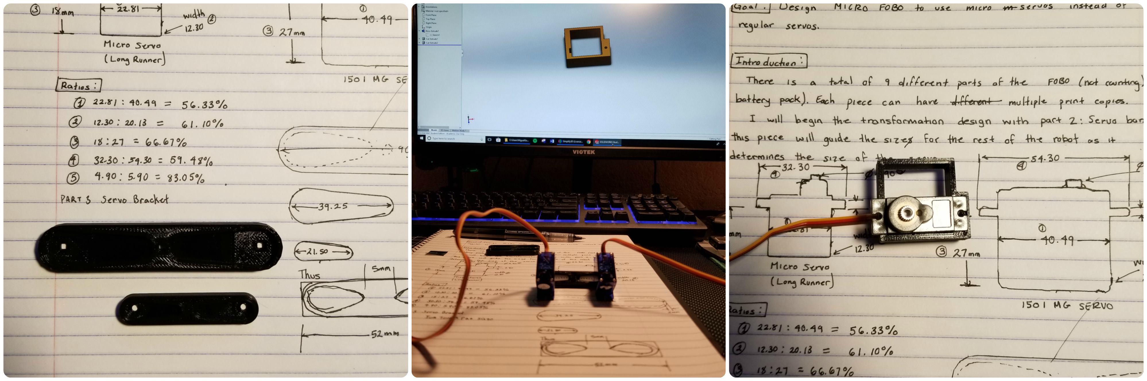
Fig. 8 Part Verification with Sketches
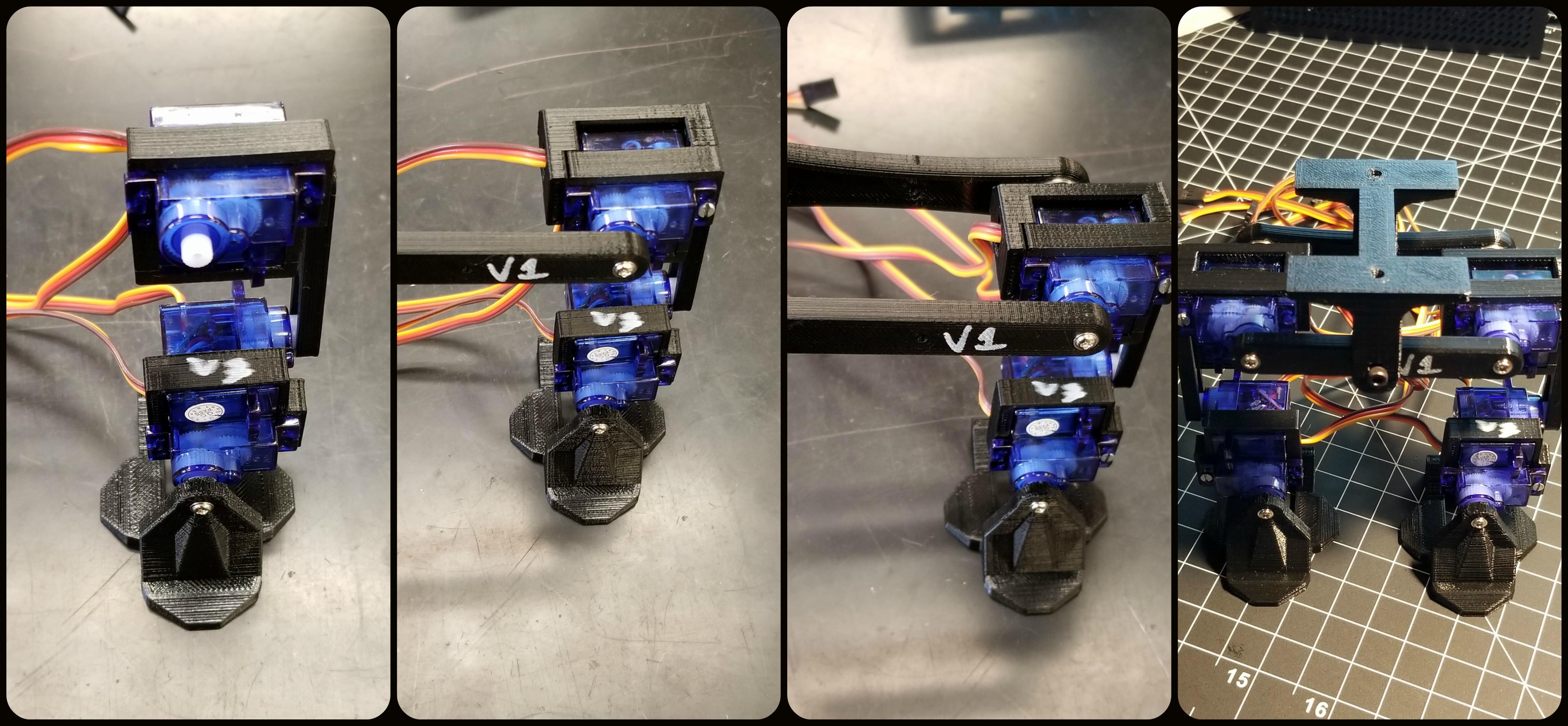
Fig.9 Assembly Process
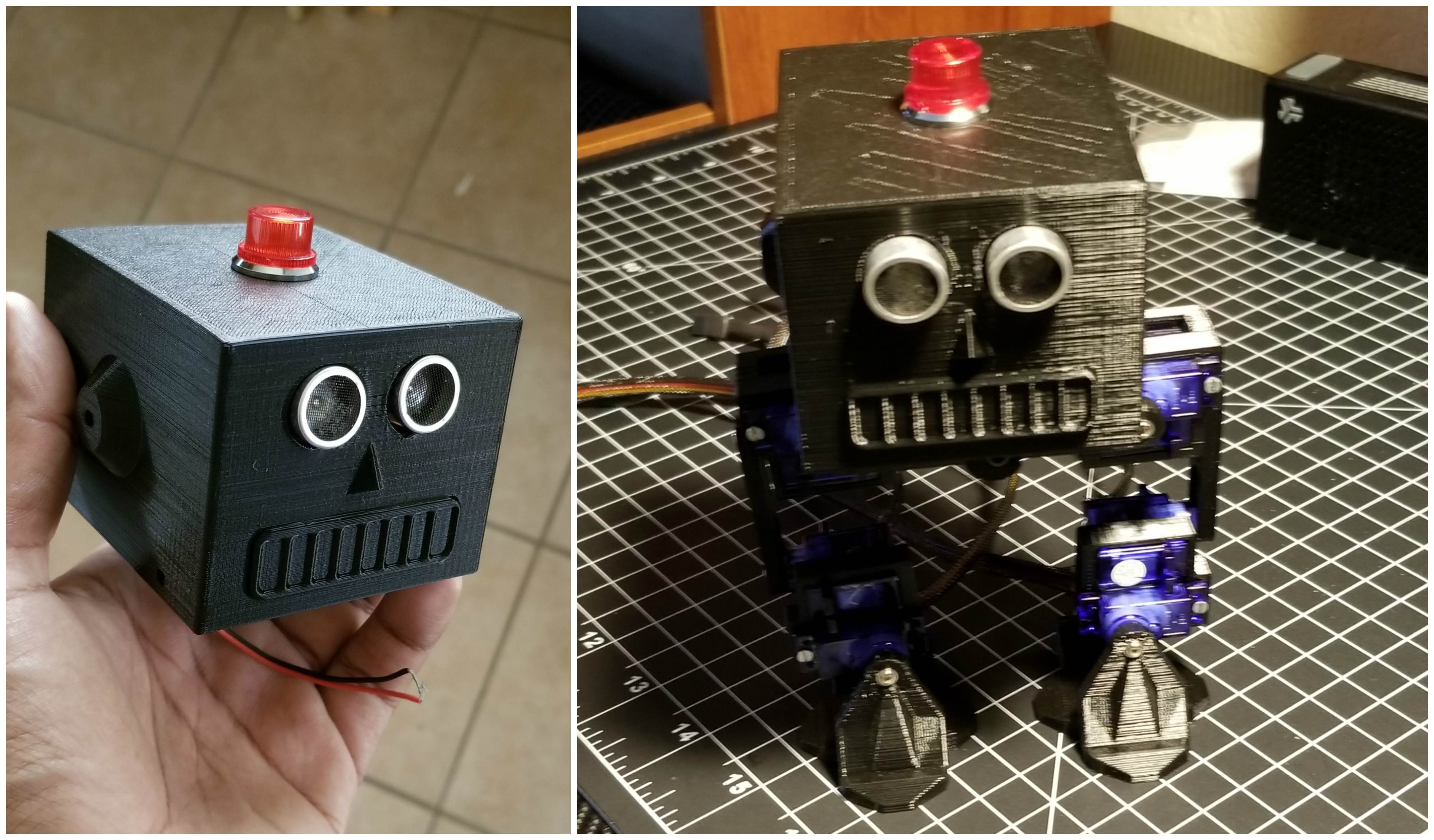
Fig.10 Head Verification and Assembly