GradBot – Fall 2019
Critical Design Review
Author/s: Taylor Manning, D&M and Shannon Hormozian, PM, MST
Verification:
Approval:
Table of Contents
The CDR happens somewhere towards the end of the semester, but at least a few weeks before the Final Demo, so much of this information has been amended and updated. The most up to date information can be found on the Final Blog Post.
Here’s a short list of things that have been changed, removed, or updated:
- Project Objective & Mission Profile
- App Customization
- Graduation cap and supports
- All resource reports
Project Objective
GradBot is a prototype of a toy robot that is marketed to soon-to-be graduates, ages 12+. It is designed to roll like the astro-mech droid BB8, but will have a graduation cap on top and a clear sphere body showing a pyramid inside that stays upright and houses the electronics. It should be operated by the user with the Arxterra app.
Mission Profile
To design a prototype of a sphero robot toy with a mortar board cap made to cross the stage in front of a graduating student.
Basic Design
- The clear sphere
- The mortar board
- The inner robot shaped like Walter Pyramid at CSULB
- The V9
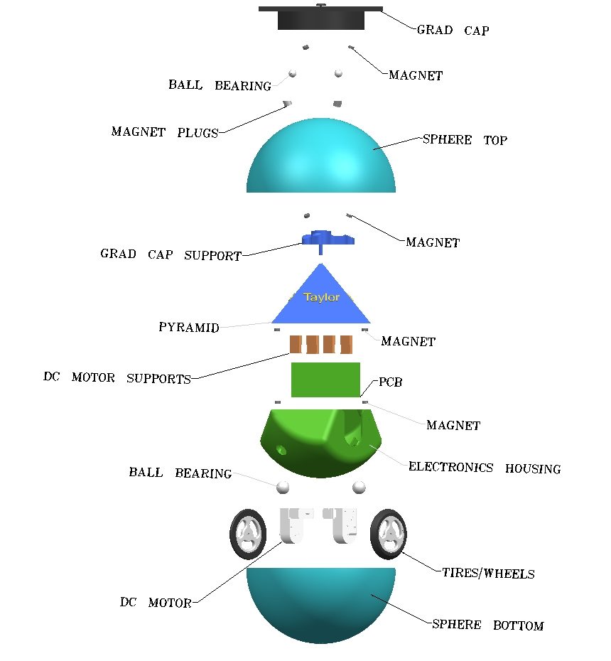
Figure 1. Exploded View of GradBot 3.0
Project Features
- Redesign of “Electronic Housing” to lower the center of mass.
- Active damping system including gyroscope and accelerometer to increase the stability.
- Mechanical design of mechanism to keep the mortar board on.
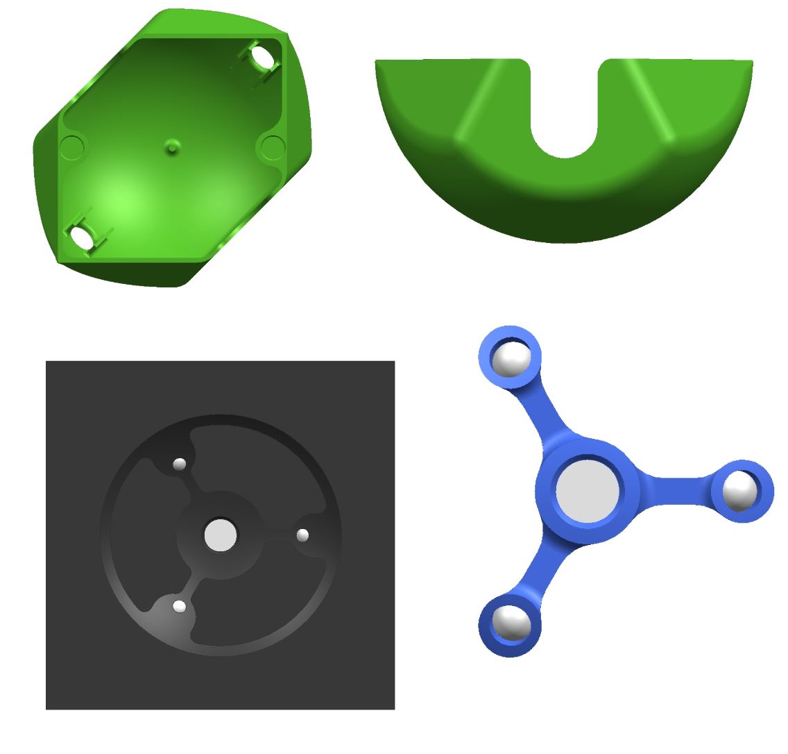
Figure 2. Model of Base and Cap Mechanism
Performance Requirements
Level 1 Requirements:
1.1 The robot shall be controlled in any x-y direction
- Verification by testing
1.2 The robot shall be aesthetically pleasing
1.3 The pyramid will be in a sphere
1.4 The robot shall have a graduation cap
1.5 The robot will be designed as a prototype for a toy (ages 12+)
Level 2 Requirements:
2.1-1 The robot shall be controlled and operated using a bluetooth module connected to the Arxterra app and connect within less than a minute when other v9 boards are not present.
- Verification by testing with the v9
2.1-2 The robot will have two gm6 motors with encoders that connect to an IMU.
- Verification by comparison of different motors (See Trade-Off)
- Verification by breadboarding to collect coordinate data
2.1-3 The robot will have two wheels that drive the motor at 1.4 m/sec
- Verification by testing the robot when fully assembled
2.1-4 The robot should have a PID for added balance
2.1-5 The robot should move in a straight path with accuracy of ±6 inches
- Verification by testing along a drawn straight path to see amount of deviation
2.1-6 The robot should have a low center of mass for added balance
- Verification by trial and error, adding/subtracting weight until best results with lowest COM is found
2.2-1 The internal electronics and all sensors will be hidden
2.2-2 The pyramid will be shaped like a 3D printed replica of the Walter Pyramid at CSULB
2.2-3 The pyramid body will be blue like the Walter Pyramid at CSULB
2.3-1 The sphere will be clear
2.4-1 The grad cap shall be held on with magnets and 3D printed mechanisms
- Verification by testing mechanisms on static sphere.
2.4-2 The grad cap shall remain at the top of the clear sphere when robot is at 90°±10°
- Verification by testing on robot in motion.
2.5-1 The robot should stay intact during normal operation
Constraints & Engineering Standards
Constraints
- GradBot’s internal rover must be less than 6 inches on its maximum side
- Gradbot must move at a minimum of 1.5 m/s (average walking speed)
- Gradbot must not exceed 3 kg
- Disassembly and reassembly of the robot shall be constrained to 20 min total
Standards
- Software shall be written in the Arduino De facto Standard scripting language and/or using the GCC C++ programming language, which is implements the ISO C++ standard (ISO/IEC 14882:1998).
- All 3DoT robots shall incorporate the 3DoT v8 or later series of boards.
- All 3DoT robots shall be controlled via Bluetooth 4.0 in compliance with the Bluetooth Special Interest Group (SIG) Standard (supersedes IEEE 802.15.1).
System & Subsystem Design
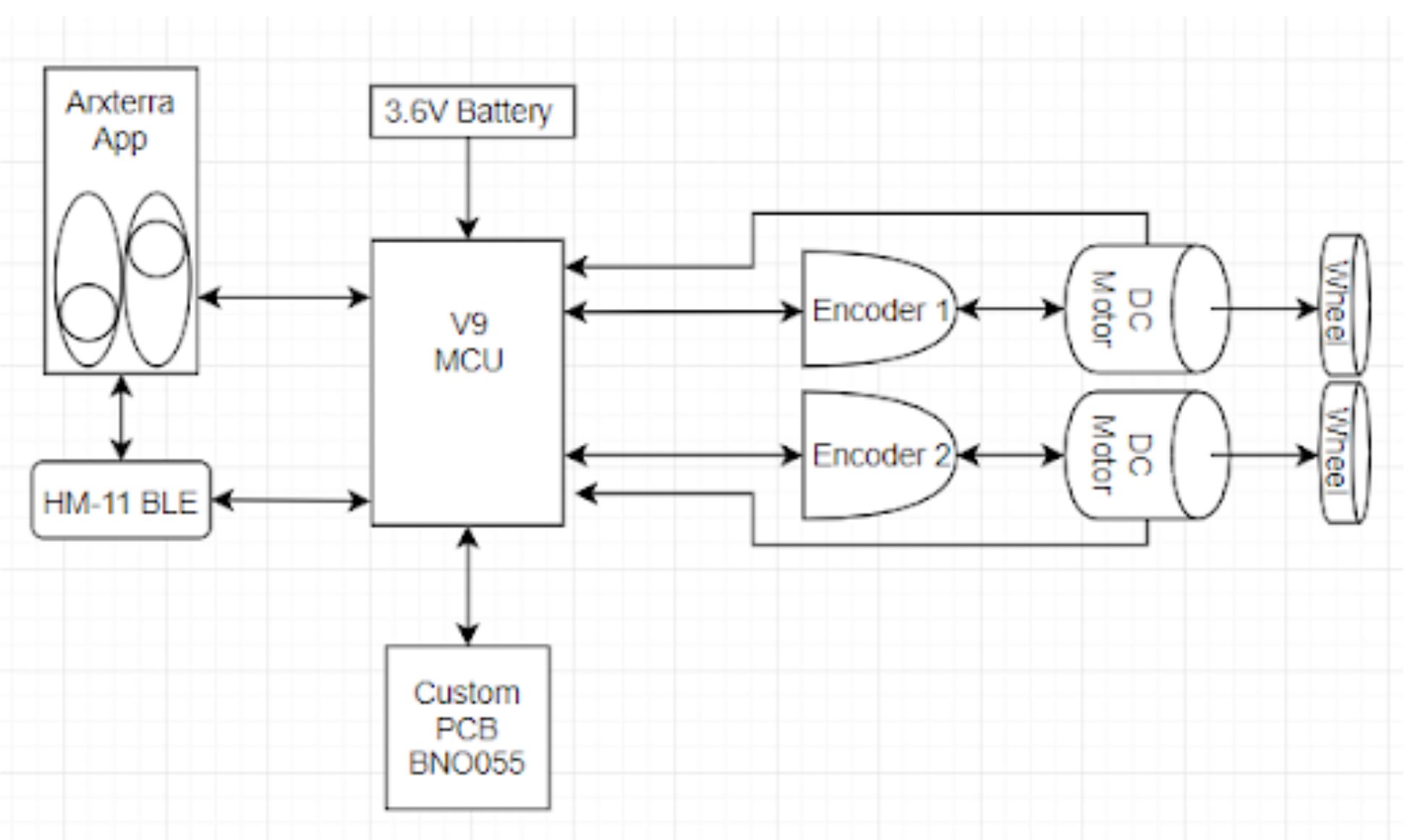
Figure 3. System Block Diagram
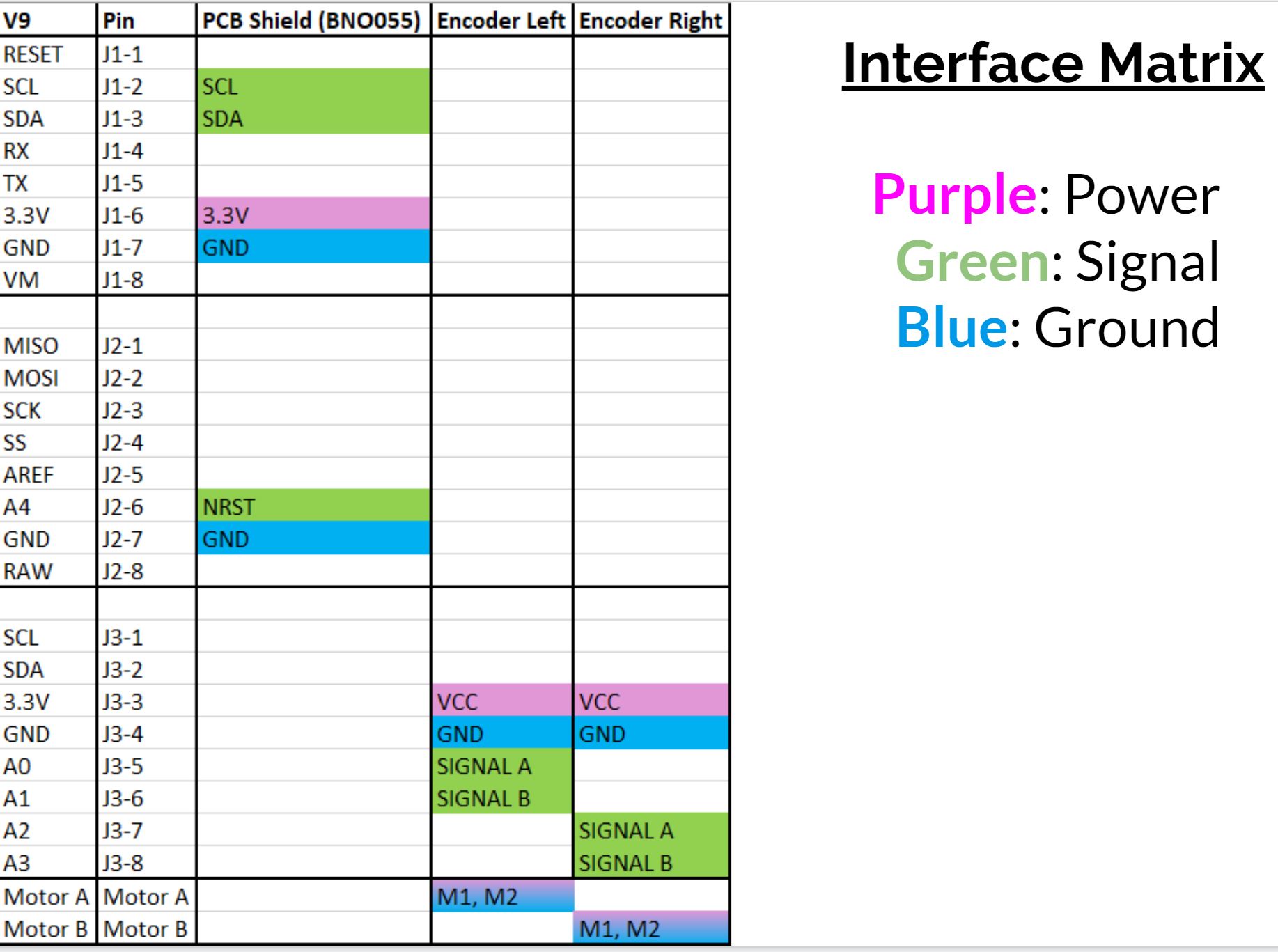
Figure 4. Interface Matrix Table
Mission Command and Control
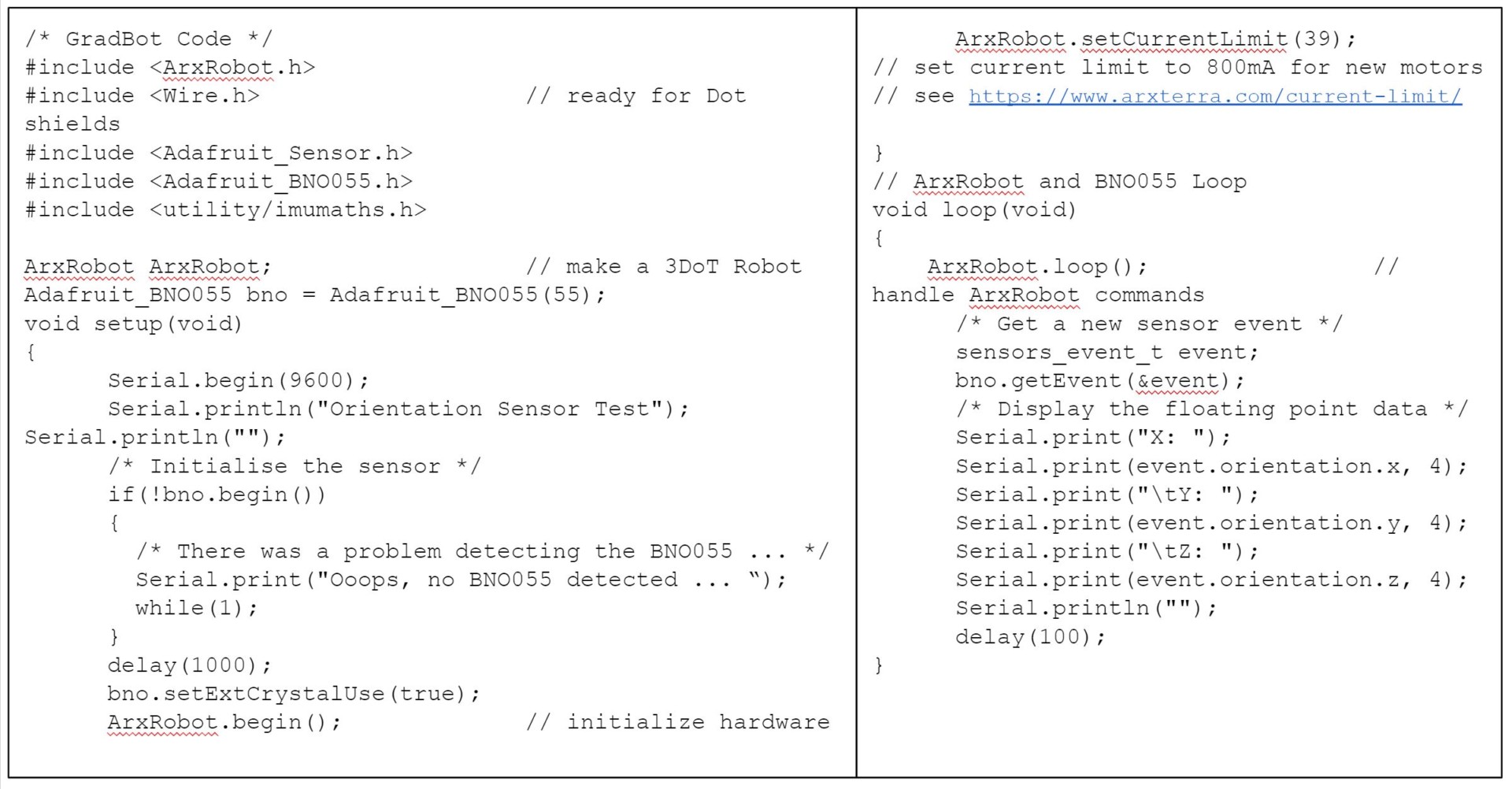
Figure 5. GradBot Test Code
App Customization
Two Modes:
- Moving forward in a straight line at set speed
- User will input desired speed and set robot on the ground
- User will then move a slider to move the robot forward
- User Controlled Movement
- User will have full control of the robot; forward, left, and right
- For this, the PID written for the Z axis will be bypassed
Each direction (X, Y, and Z) will have its own PID code section:
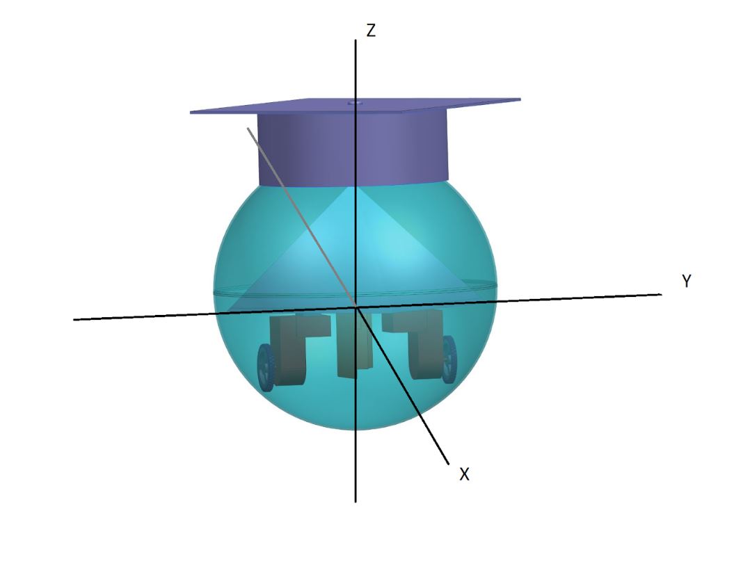
Figure 6. The 3 axis of GradBot
Electronic System Design
Components List
- V9 board by Arxterra
- Implementing 3DoT technology
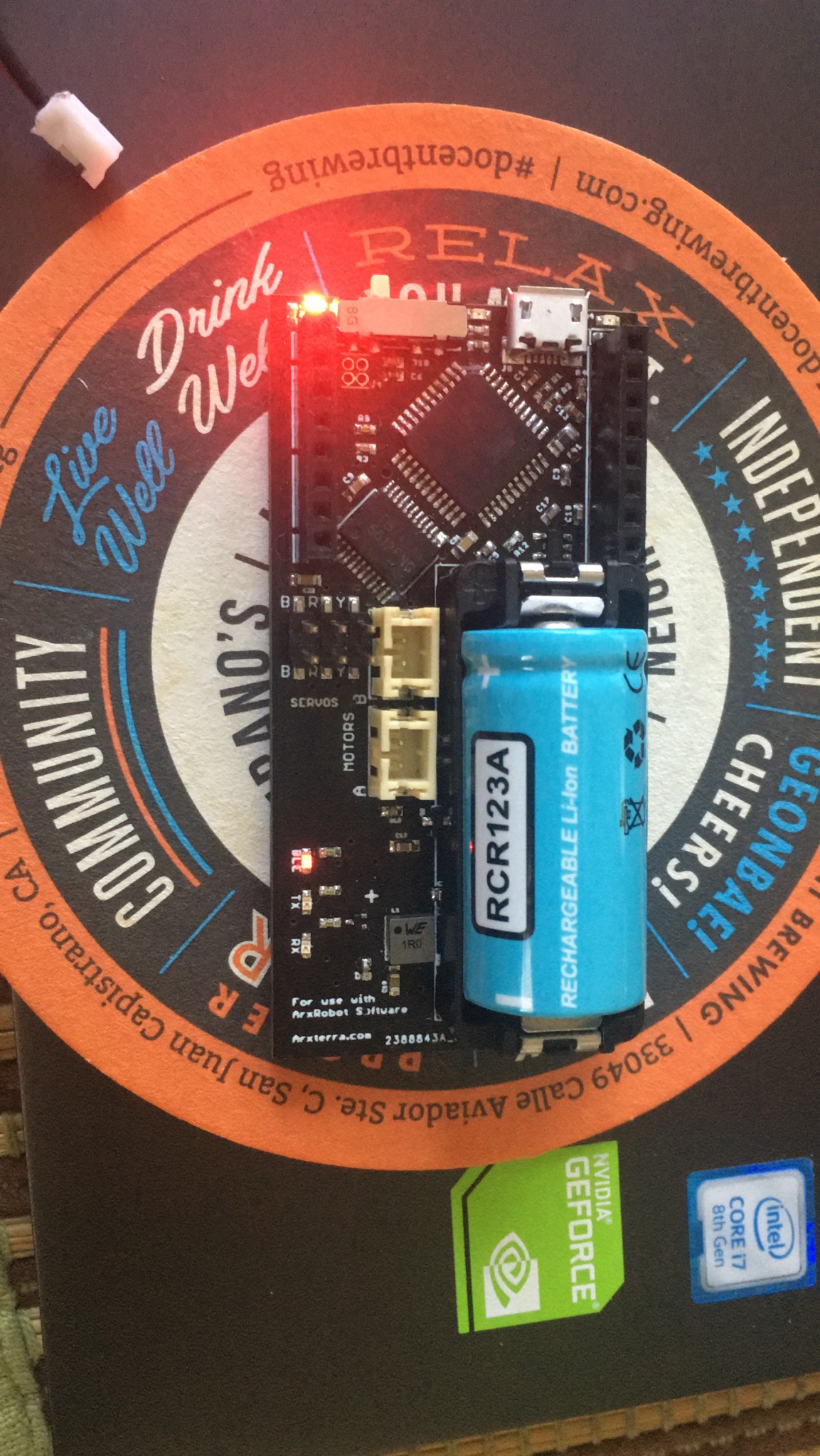
Figure 7. V9 board from 3dot robot kit
- 120:1 Mini plastic gear motor with extended back shaft
- Same as gm6 with the exception of 800 mA stall current
- Magnetic encoders on motor shaft
- To communicate with the IMU to adjust

Figure 8. Plastic gear motor with 90 Degree shaft and quadrature encoders
- IMU: BNO055 – Magnetometer, gyroscope and accelerometer
- Easy to use all three in one board (not very many made)
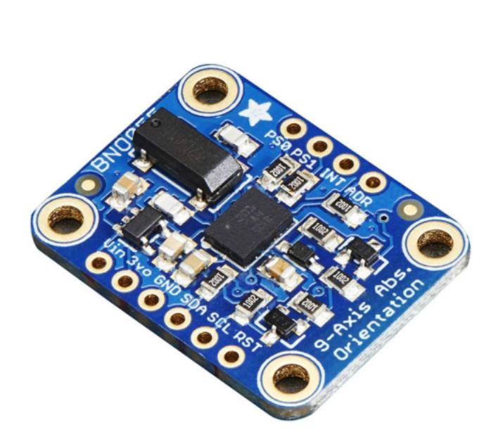
Figure 9. BNO055 breakout board which includes an accelerometer and a gyroscope
Firmware (PID Controller)
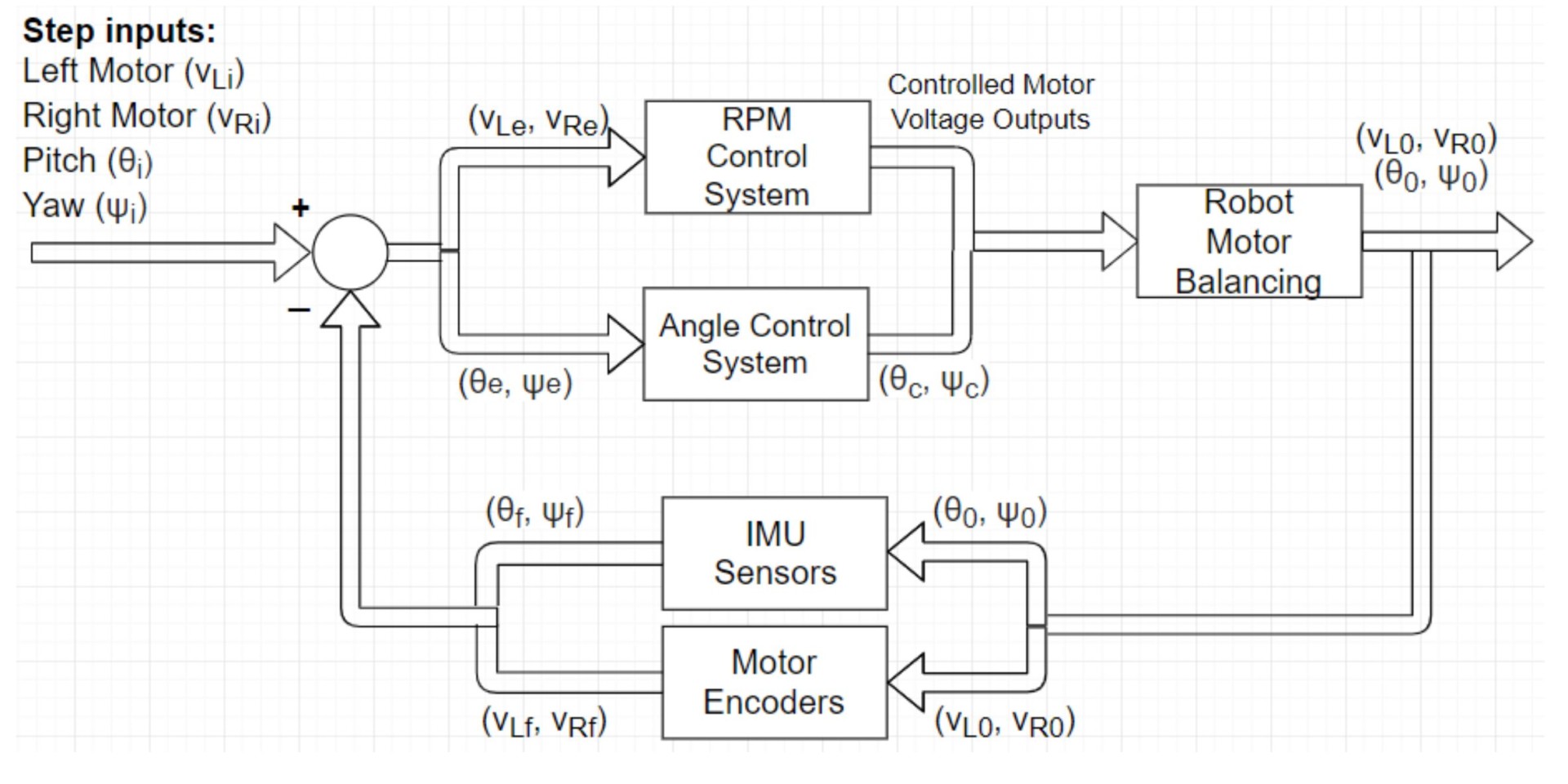
Figure 10. More detailed system block diagram for PID controller
- Step input: velocity from user in app
- Simultaneously:
- left encoder reads rpm (derived from voltage value)
- right encoder reads rpm (derived from voltage value)
- IMU reads pitch and yaw (Euler angle in degrees)
- Determine the offset of pitch and yaw from predetermined acceptable ranges (+- 10 degrees as a start)
- For angles out of range – convert into voltages for motors in control panel: tricky.
- Left and right motor speeds are adjusted from a loop to balance the robot.
PCB Design
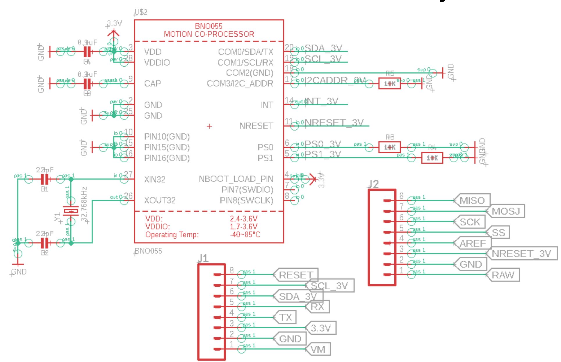
Figure 11. PCB Schematic
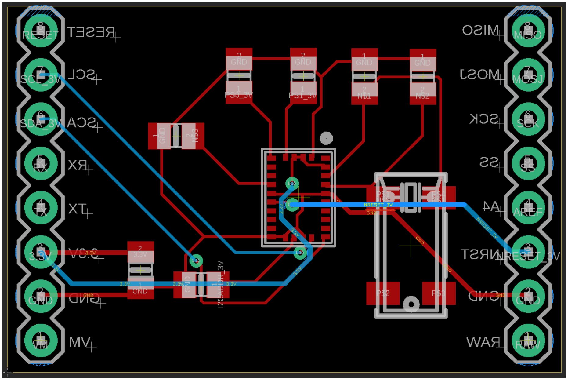
Figure 12. PCB board layout. Passed ERC and DRC tests
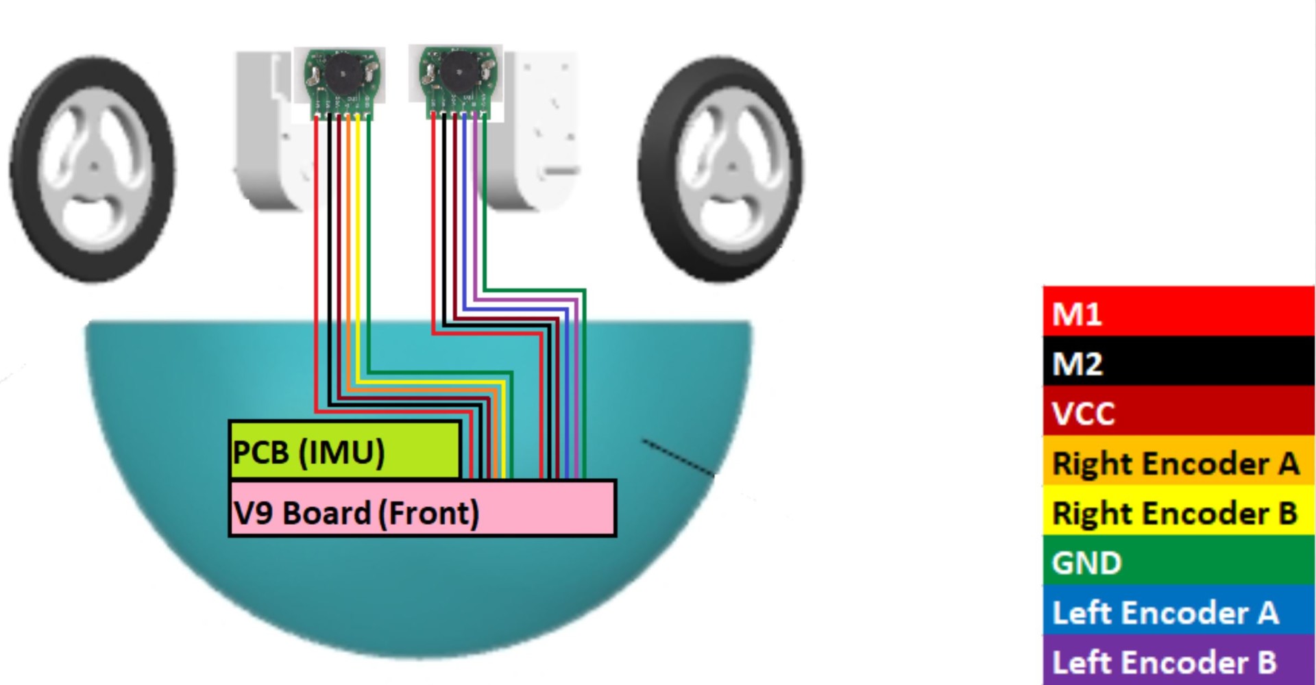
Figure 13. Cable tree
Mechanical Design
Pyramid
- Pyramid is mechanically one piece
- Small hole at peak of pyramid to attach support for mortar board.
- Newly designed base to accommodate added weight to help with balance
- Base will house all electrical components, keeping the weight and center of mass low giving it less of a wobble
- Has two magnets embedded to attach the base
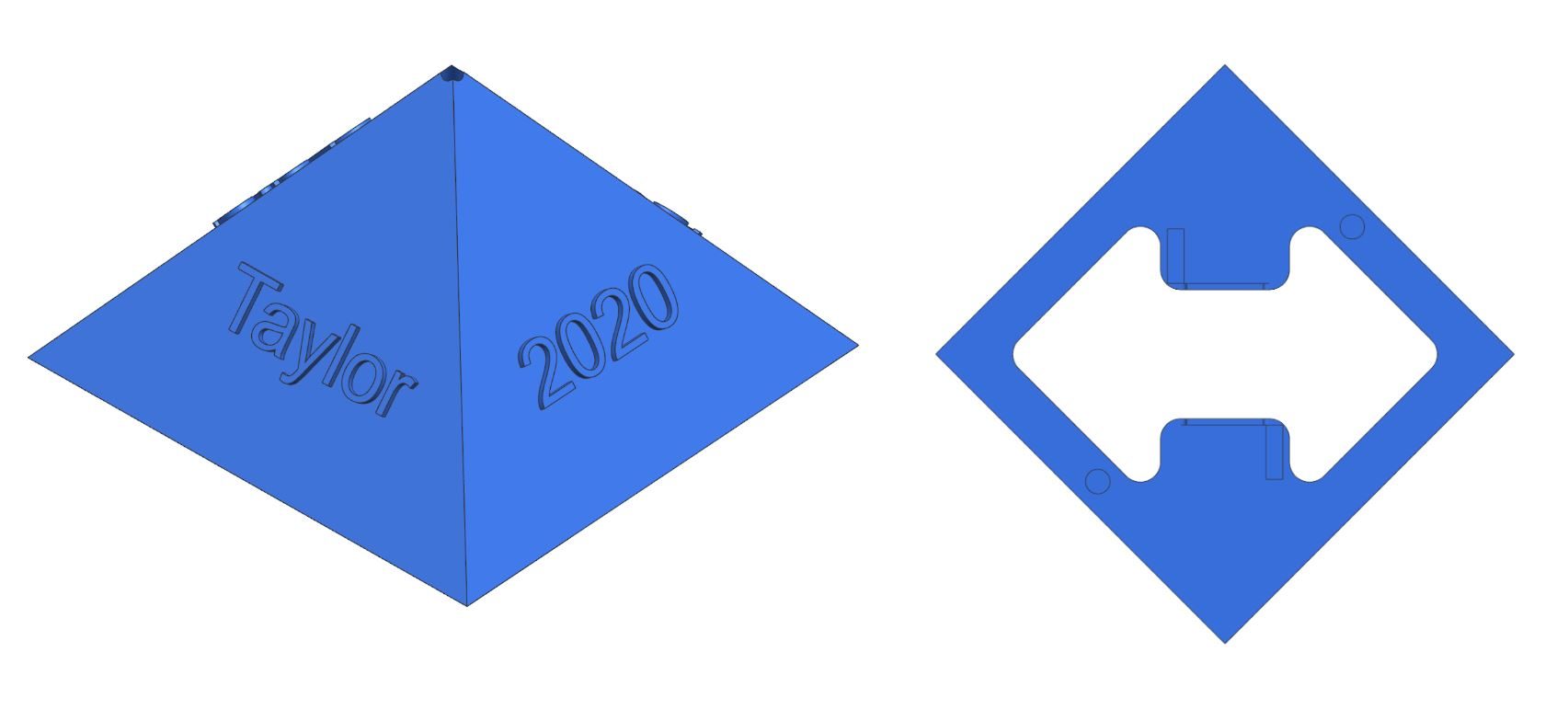
Figure 14. Pyramid Design for GradBot 3.0
Drawing
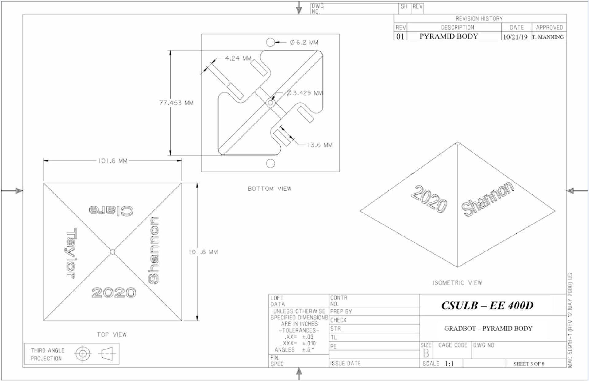
Figure 15. Renderings of pyramid body for GradBot 3.0
Trade-Off Study
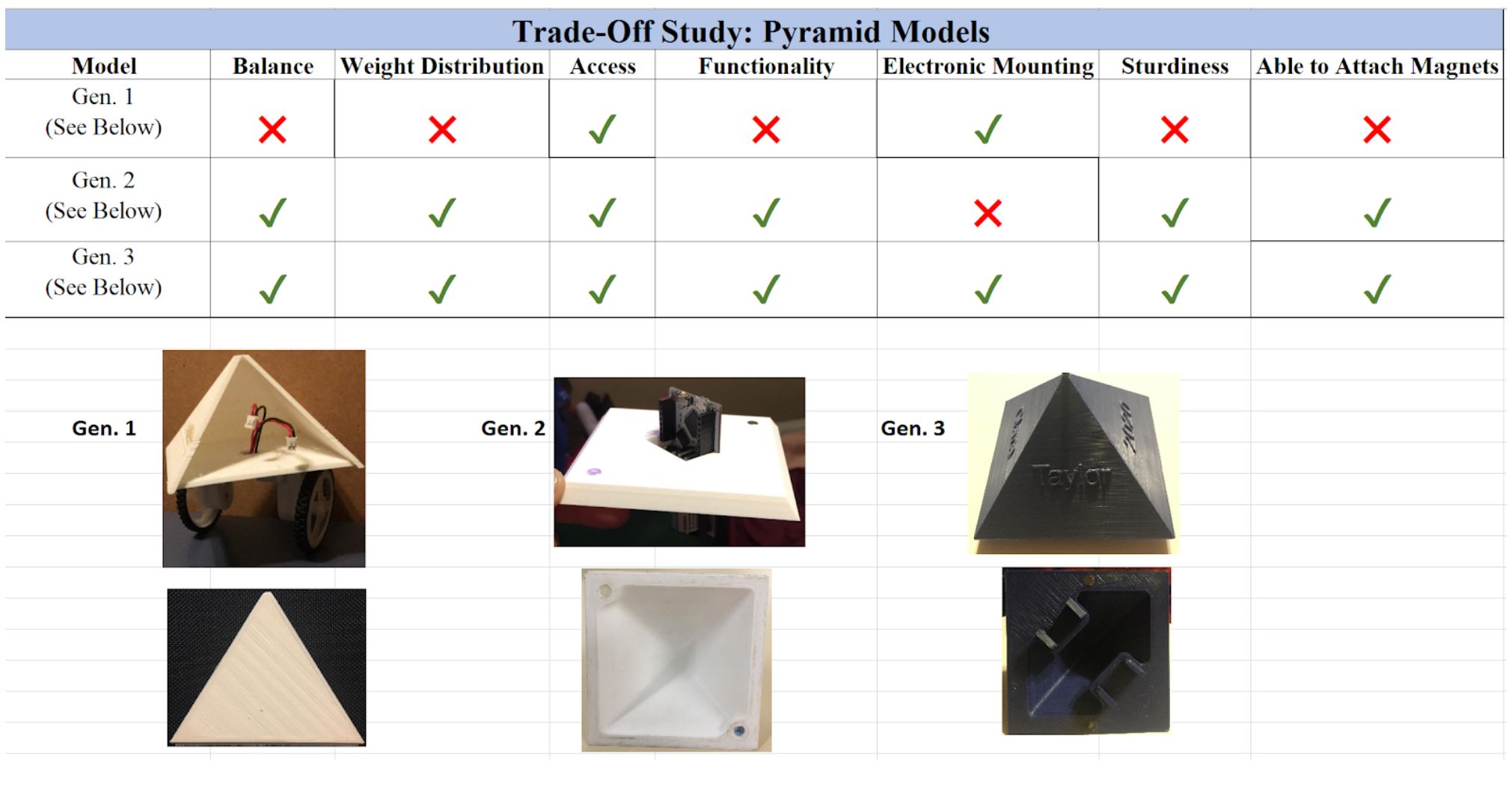
Figure 16. Pyramid body tests
Electronic Housing
- Spherical electronic housing is mechanically one piece
- Two magnets are embedded into the top to magnetically attach to the pyramid
- Will house all electrical components
- Has custom cut-outs to accommodate the shape of the gm6 motors.
- Contains two embedded ball bearings with clevis type fastenings that flex just enough to insert the bearing to provide better stability during operation.

Figure 17. Pyramid base to house electrical components
Drawing
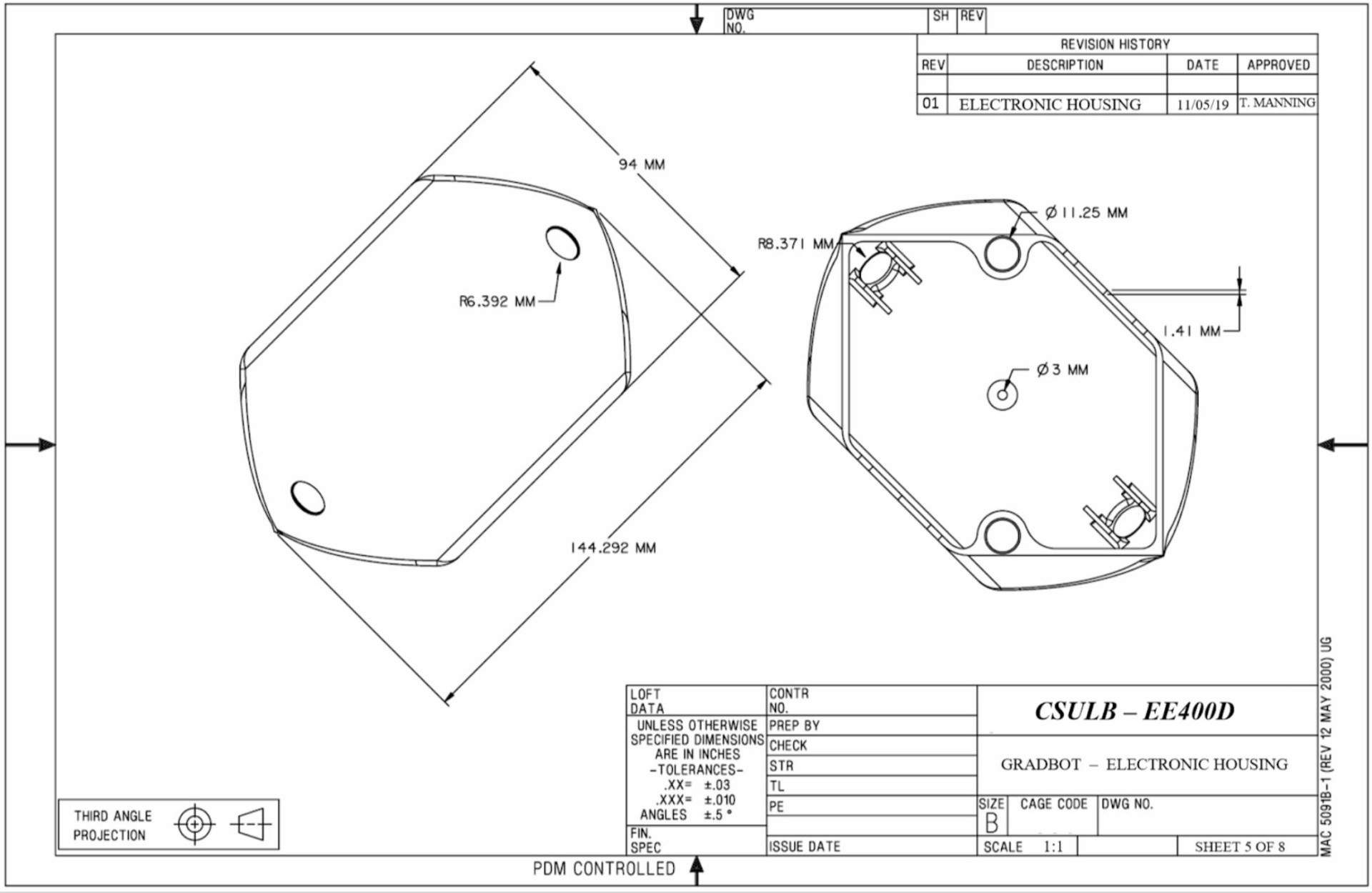
Figure 18. Renderings for pyramid base
Trade-Off Study
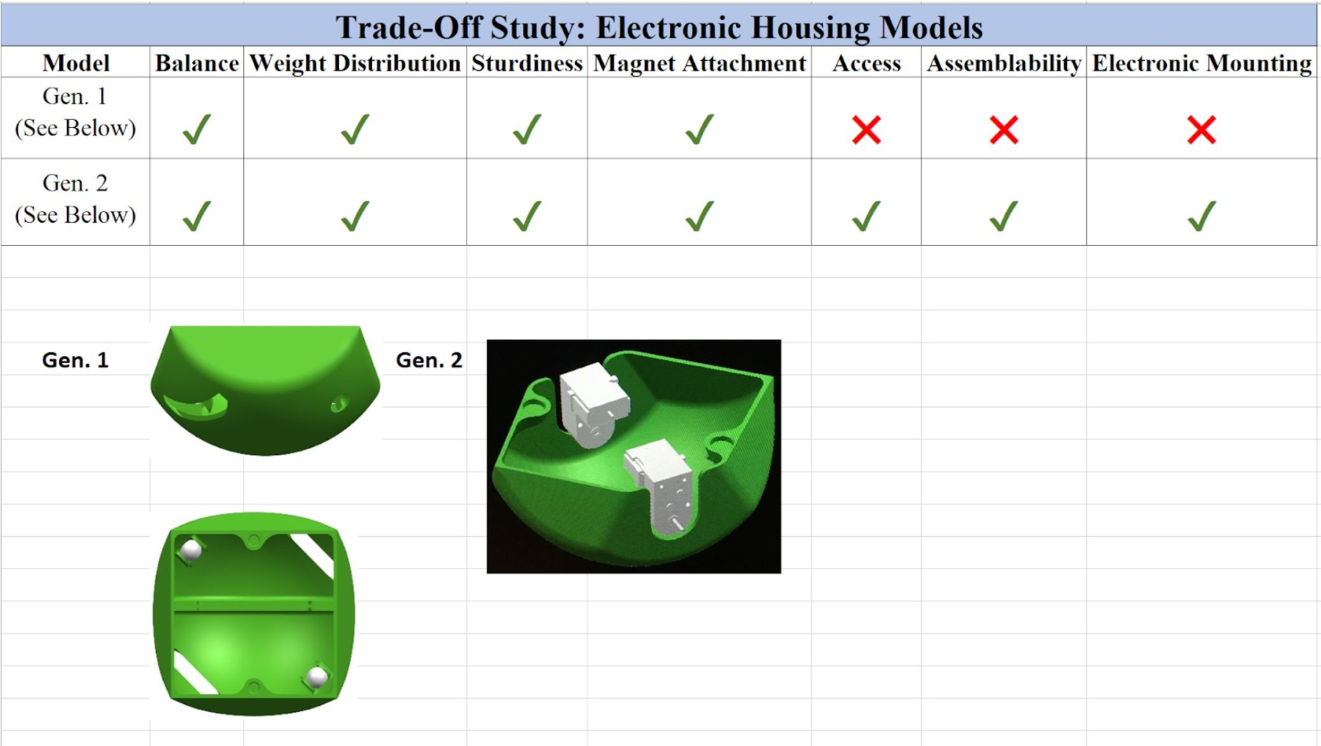
Figure 19. Trade off study for electric housing/pyramid base test
Graduation Cap
- Subtraction function used to perfectly mimic the sphere shape into the base of the mortar board
- Ball bearings and magnets were also needed
- The ball bearings helped smooth the movement of the cap when the sphere was spinning
- The magnets were to attract the cap to the magnetic support inside the sphere
- Magnets are placed at robots center line.
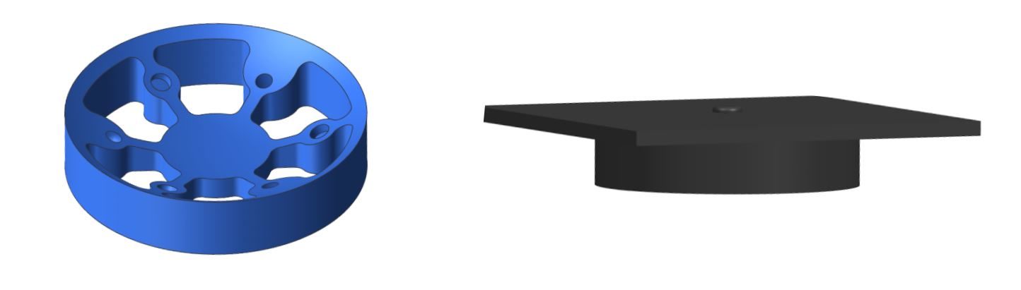
Figure 20. 3D designed cap and outer mechanism
Drawing
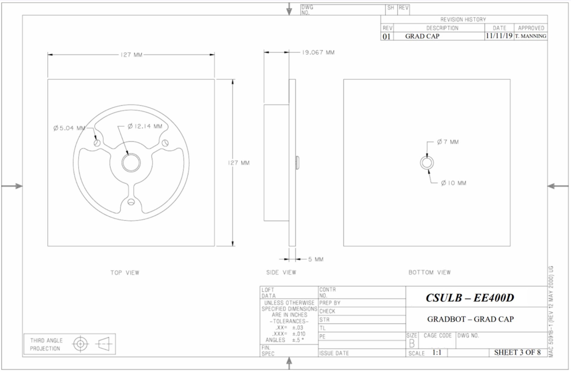
Figure 21. Renderings for graduation cap
Trade-Off Study
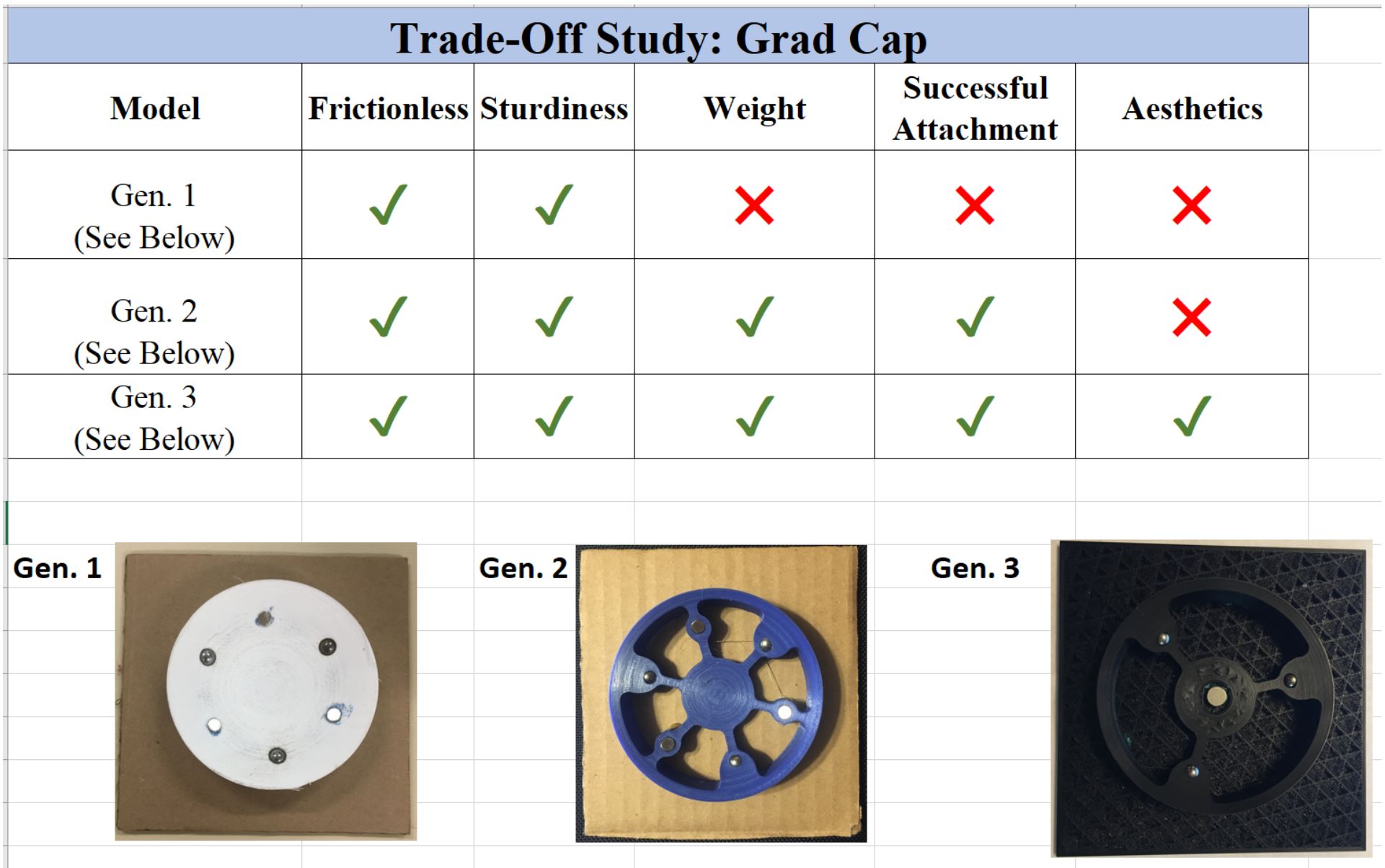
Figure 22. Trade off study for graduation cap tests
Graduation Cap Support
- Matches the base of the mortar board exactly as well as fitting perfectly against the curve of the inner part of the sphere.
- Has one embedded magnet.
- Any excess material was removed to keep the piece light.
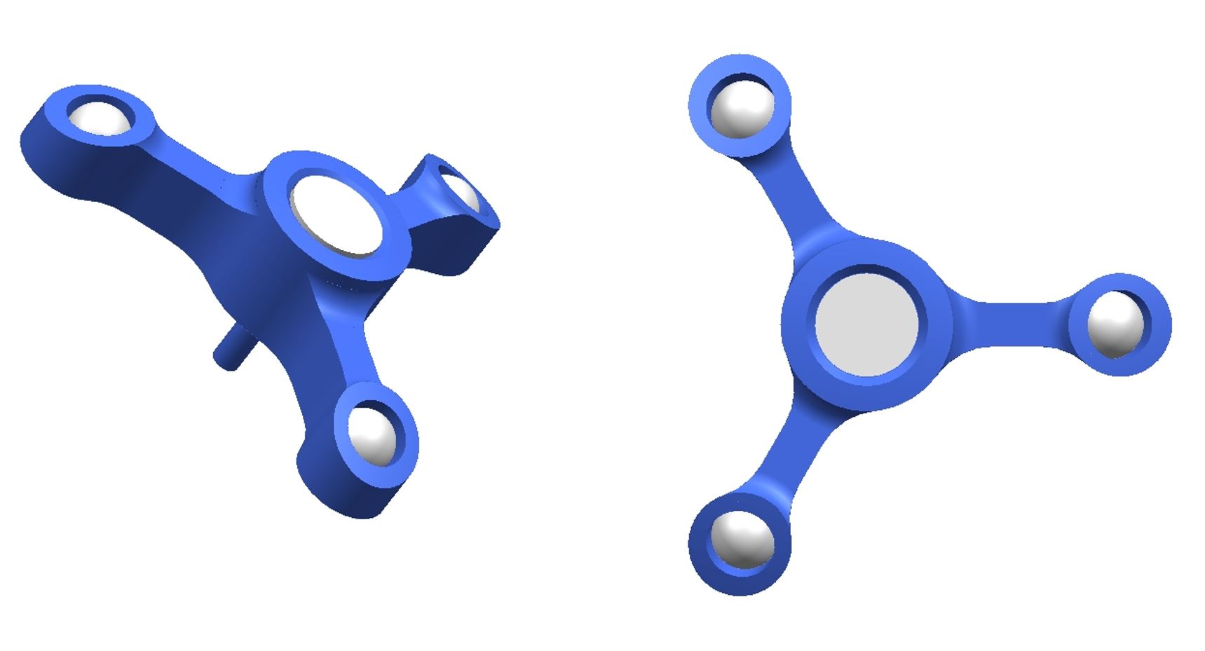
Figure 23. Internal cap mechanism
Drawing
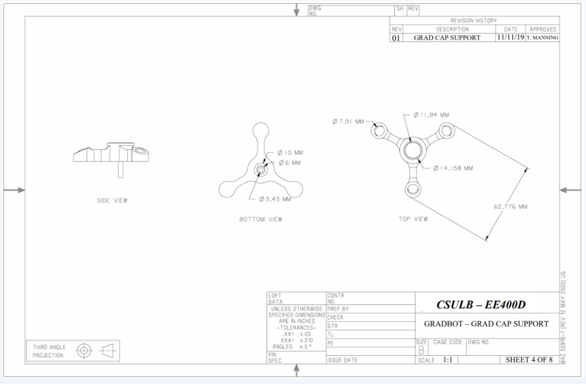
Figure 24. Renderings of internal grad cap support
Trade-Off Study
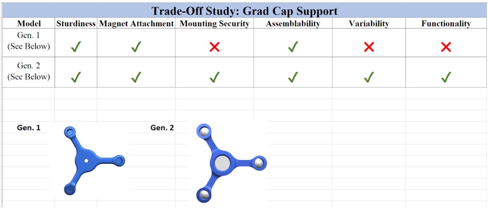
Figure 25. Trade off study for internal support tests
Tires/Wheels
- Slanted tire design to perfectly hug inner sphere wall
- This allows more surface area to come in contact with the sphere giving the robot more forward movement
- Wheel size and relative shape was kept incredibly similar to the wonderfully designed 3dot wheel
- Wheel is mounted so that it sits about 45mm from the ground.
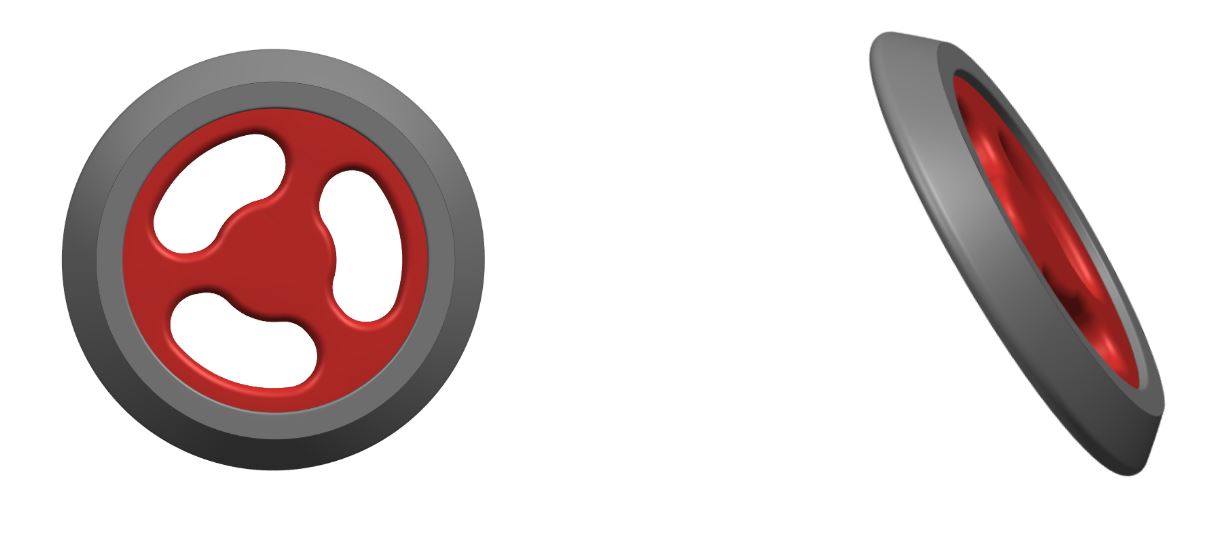
Figure 26. 3D modeled wheels
Drawing
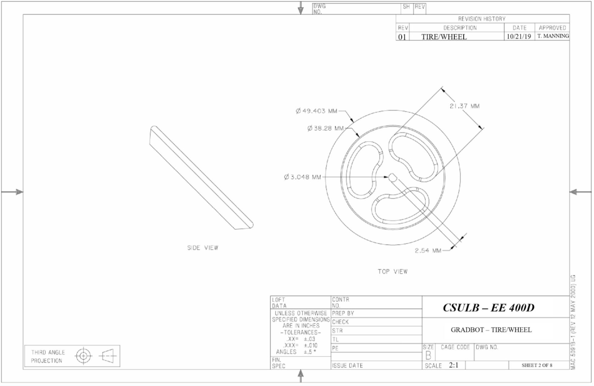
Figure 27. Renderings of new wheels
Trade-Off Study
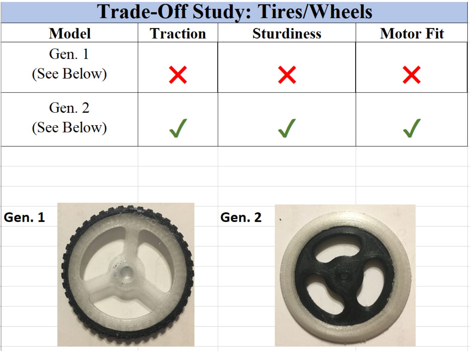
Figure 28. Trade off study of wheels
DC Motor Mounts
- Mechanically fastens the DC motors to the bottom of the pyramid
- Implemented slots for sliding the motors in
- Simplest method for fastening the motors so far
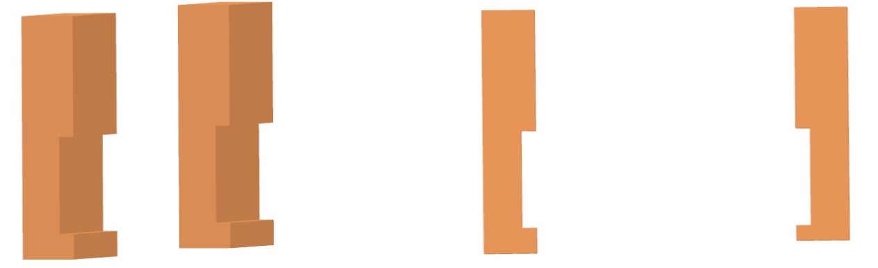
Figure 29. Motors mounts
Drawing
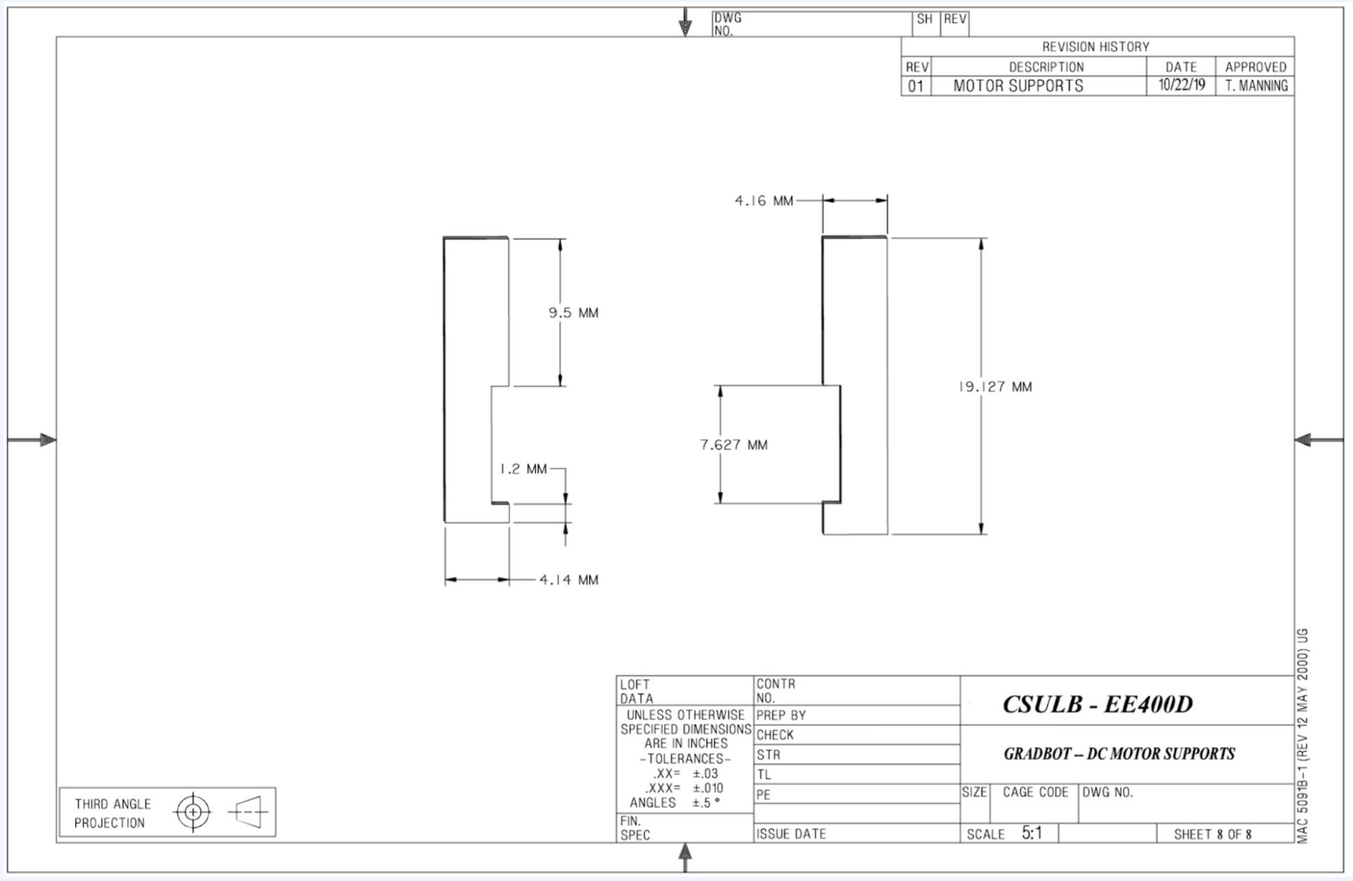
Figure 30. Rendering of motor supports
Rapid Prototyping/Initial Prints
Pyramid Generation 1:
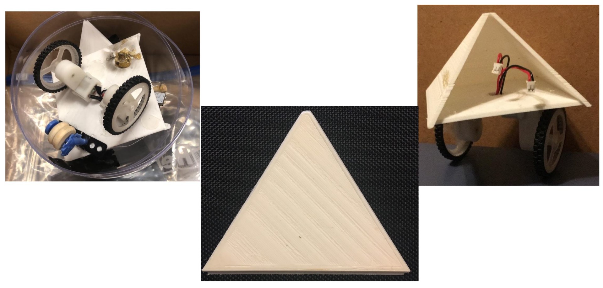
Figure 31. Images of Gradbot 1.0
- Our first pyramid was a rough 3D print that matched the size parameters we were faced with using a 6” sphere.
- Size constraints were the first issues exploited by this rapid prototype. We realized the size of the v9 board would prevent us from putting it inside the size pyramid we were working with.
- We attempted to implement a sliding door on the side to quickly and easily access internal electronics.
- We realized with the size of the pyramid we were working with, a sliding door was not going to be practical for this application.
- Our pyramid had the tendency to topple forward/backward depending on which way it was being operated. To mitigate this issue, we bought a toy motorcycle and used the front forks to attach wooden wheels that would act as supports against the outer sphere.
- This eventually led us to the design of bearings in the electronic housing piece.
Pyramid Generation 2
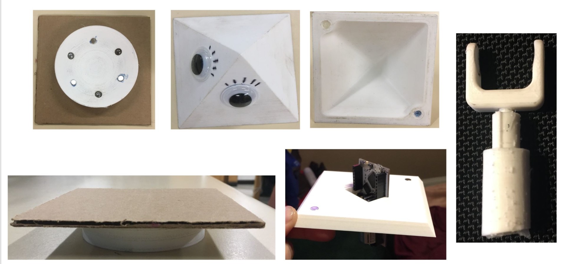
Figure 32. Images of Gradbot 2.0
- Our second pyramid allowed us to use the weight of the v9 for better balance and implement a new idea for mounting electronics. We also implemented separating the pyramid into two pieces for access to the v9, keeping the pieces together by magnets.
- This worked better than the previous, but still needed improvements. We also knew that electronics couldn’t be exposed for the final product so a new solution was going to be needed.
- Original Mortar Board design was good, however, it was a little too heavy and wouldn’t stay on top of the sphere in operation.
- We implemented a new shaft and clevis to hold a ball bearing as a method for supporting the pyramid from toppling over during motion.
Tires/Wheels

Figure 33. First print of new wheel design
- Our new design of the wheels originally had a plus sign shaped center cut-out where we used special wheel adapters that would attach to the splined shaft of the provided gm6 motors.
- This was to improve efficiency of the wheel operation because we experienced a lot of slipping inside of the wheel center when just using a bushing on the 3dot provided wheels.
- Final design of the wheels moved to a D-shaped center cut-out to match the new gm6 motors being used that included encoders.
- The tires contoured shape remained consistent through both wheel designs.
Other Experimental Results
Mortar Board Testing
Test #1: Fail
- Original three legged spindle with smallest sized magnets that mirrors three magnets embedded in the base of the cap along with ball bearings
- Theoretically would allow the cap to slide along the outside of the sphere
This design was intended to allow the mortar board to glide along the outside of the sphere with minimal friction but strong enough magnetic pull that the mortar board would not fall of during motion. The rod the the three legged spindle sat on failed to prevent the spindle from rising to the top. Because of this, the magnets pinched the top sphere and created resistance that our motors could not overcome.
Test #2 : Fail
- Same three legged spindle with same outer cap base mechanism
- Added small spring to pin attaching spindle to tip of pyramid to give movement and help push base of robot (and wheels) down
This test implemented a spring which aimed to better keep the spindle in place while also creating a downward force to help better engage the wheels with the lower sphere. This idea would have worked if we were working with a housing that could be securely fastened shut. Because the sphere we are using to implement this robot type, we faced the issue of the spring creating too much outward force causing our sphere halves to separate.
Test #3: Pass/Fail
- Testing the new three legged spindle that has 3 bearings instead of magnets on the legs, one central magnet, and spring/bump stop to prevent from falling to low.
This test implements our updated parts including the new Grad Cap Support and Mortar Board. During this test, we were able to test out the ability to keep a graduation cap on the top of sphere in motion. Our test was successful to a point, but due to an issue with the tires for our robot (which are not gripping the inner sphere well enough) forward motion is stunted and it rolls unevenly and usually in a circular motion. We were able to prove that a graduation cap can and will stay on while the robot is moving, however we were not able to see steady motion from the robot to determine conclusively how well it will operate in total.
Mission Systems & Test
Verification Test Plan Overview
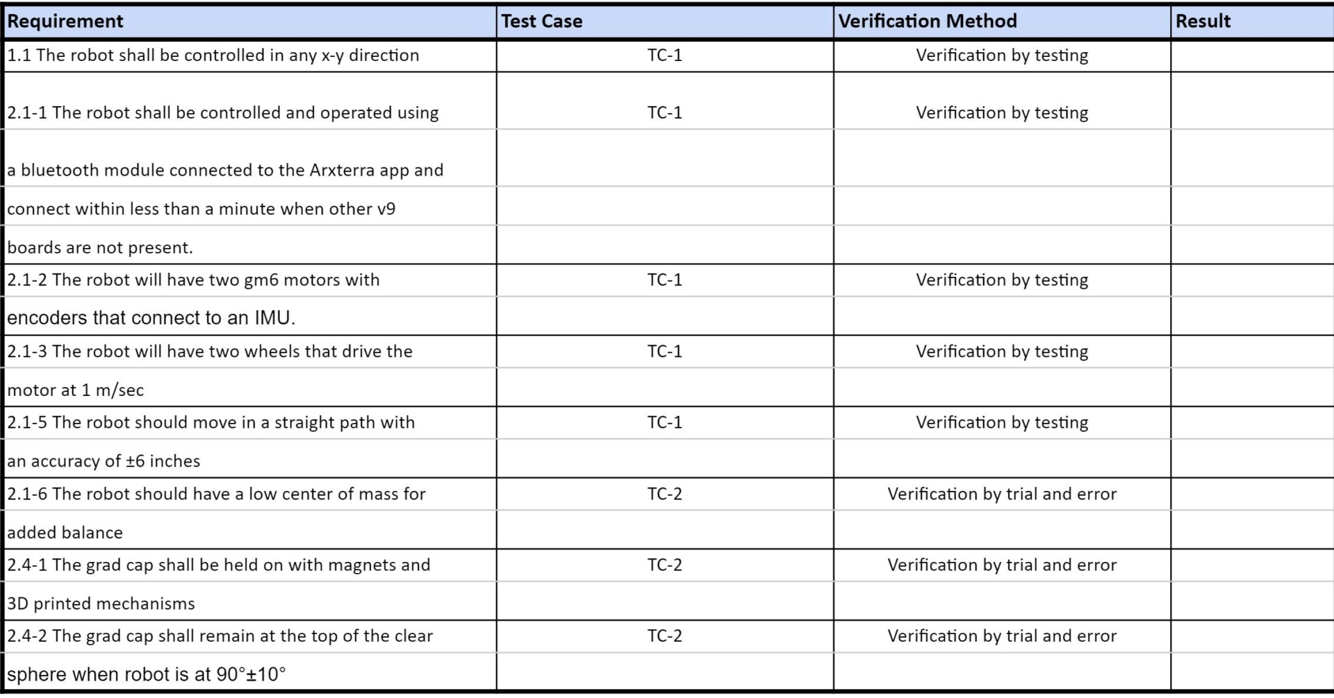
Figure 34. Test Plan Overview
Test Case #1
Requirements:
- 1.1 The robot shall be controlled in any x-y direction
- 2.1-1 The robot shall be controlled and operated using a bluetooth module connected to the Arxterra app and connect within less than a minute when other v9 boards are not present.
- 2.1-2 The robot will have two gm6 motors with encoders that connect to an IMU.
- 2.1-3 The robot will have two wheels that drive the motor at 1 m/sec
- 2.1-5 The robot should move in a straight path with an accuracy of ±6 inches
Steps to perform verification:
- Assemble robot
- Create 2 paths
- Must be at least 5 meters
- Should have at least one left turn, one right turn, and at least 1 meter of straight path
- Should be flat and relatively smooth surface
- Should be at least 20 inches wide with tally marks marking every inch to test for accuracy
- Second path should be completely straight with a measurable lane to test accuracy
- Verify connectivity between v9 and Arxterra app
- Place robot on designed path
- Use app to move robot through path
- Use stopwatch to time speed
Test Case #2
Requirements:
- 2.1-6 The robot should have a low center of mass for added balance
- 2.4-1 The grad cap shall be held on with magnets and 3D printed mechanisms
- 2.4-2 The grad cap shall remain at the top of the clear sphere when robot is at 90°±10°
Steps to perform verification:
- Assemble 3D printed robot.
- Complete preliminary move test to analyze instability.
- Add weights and retest move pattern.
- Repeat step 4 until desired stability.
- Reassemble robot with added cap mechanism.
- Repeat steps 2-3 until cap acts accordingly and desired stability is achieved.
Updated Project Status
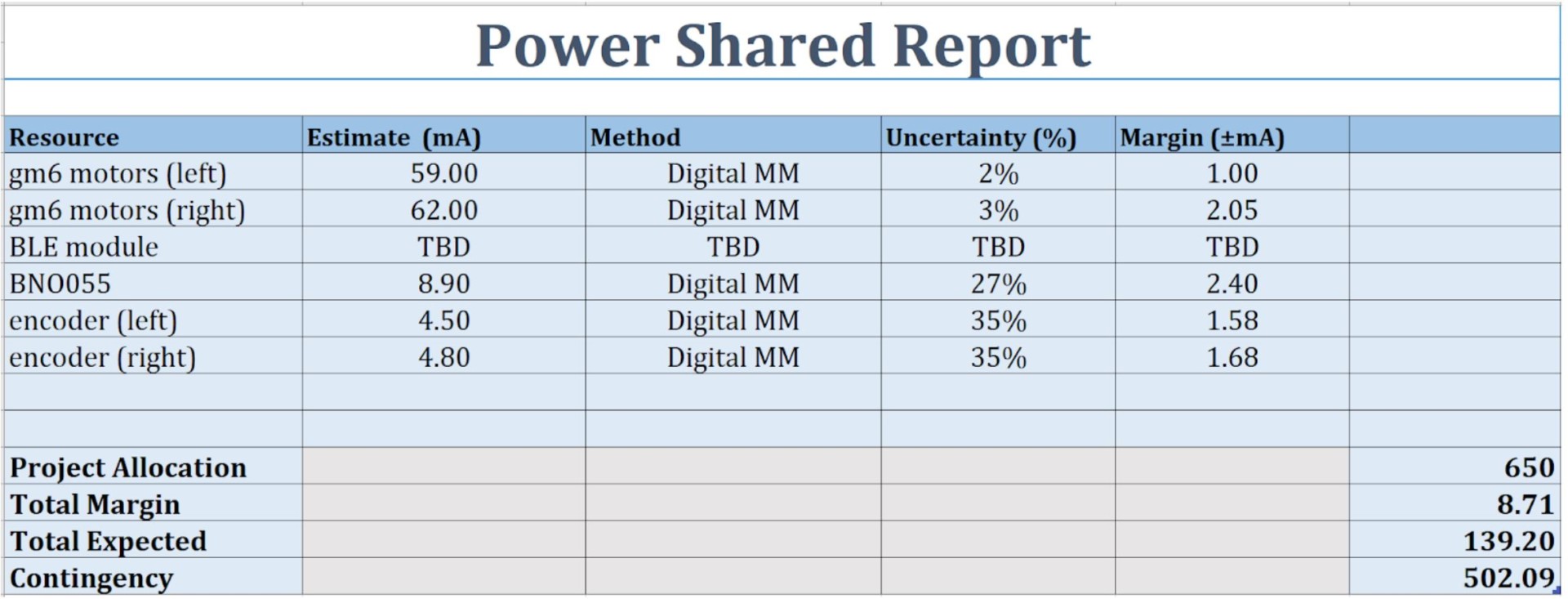
Figure 35. Power Allocation Report
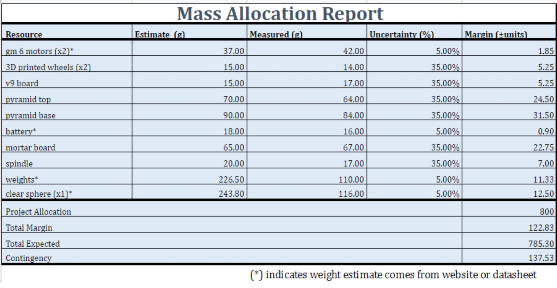
Figure 36. Updated Mass Allocation Report
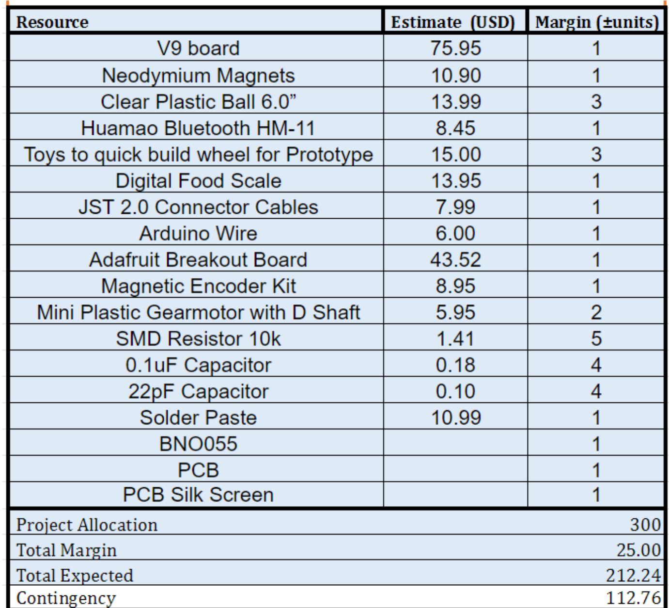
Figure 37. Updated Cost Analysis
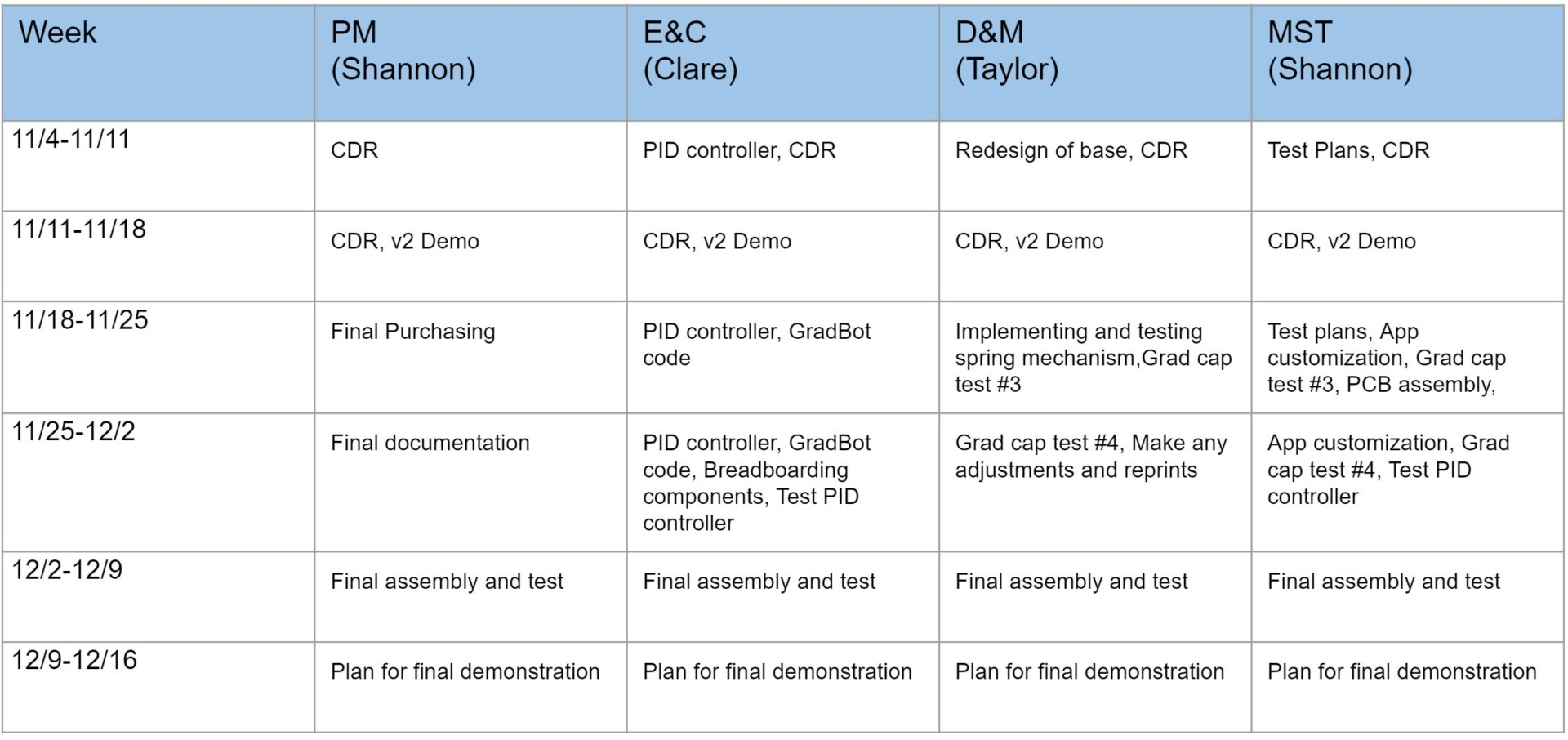
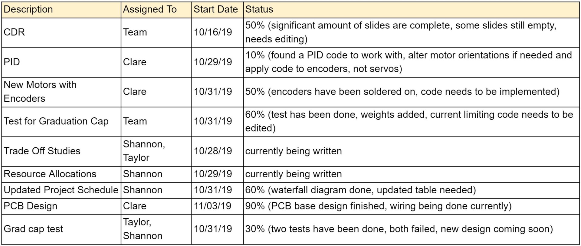
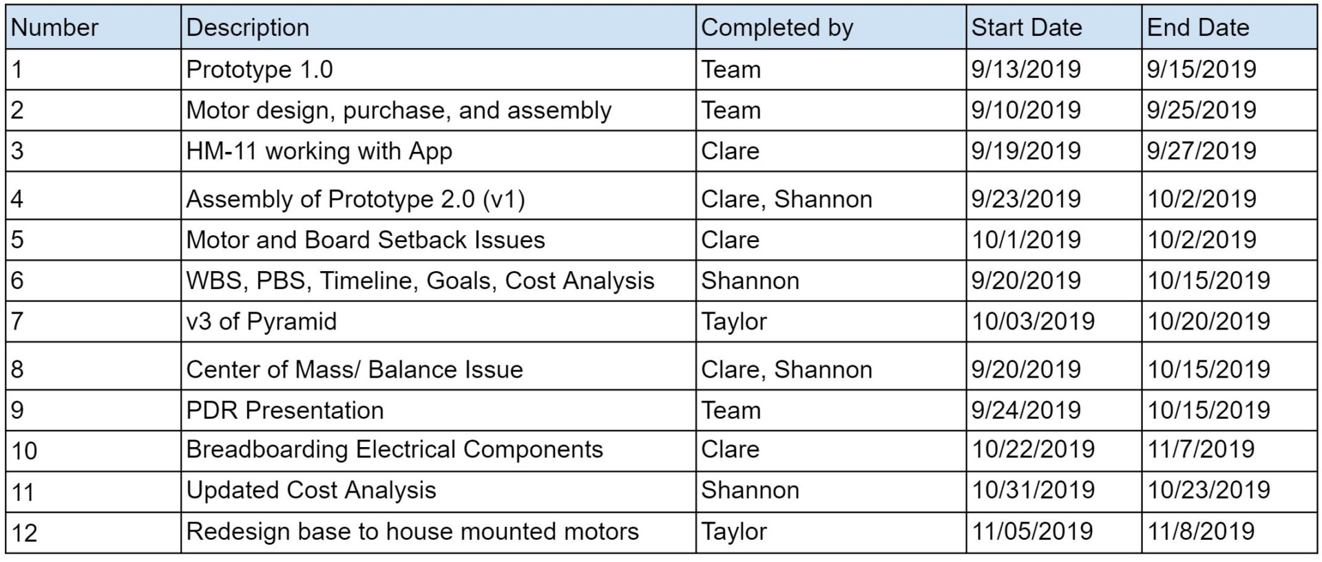
Figure 38. Updated Project Schedule
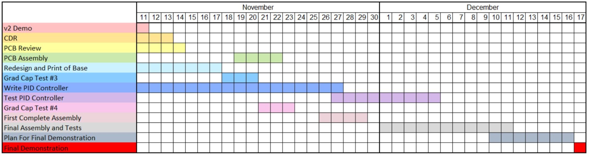
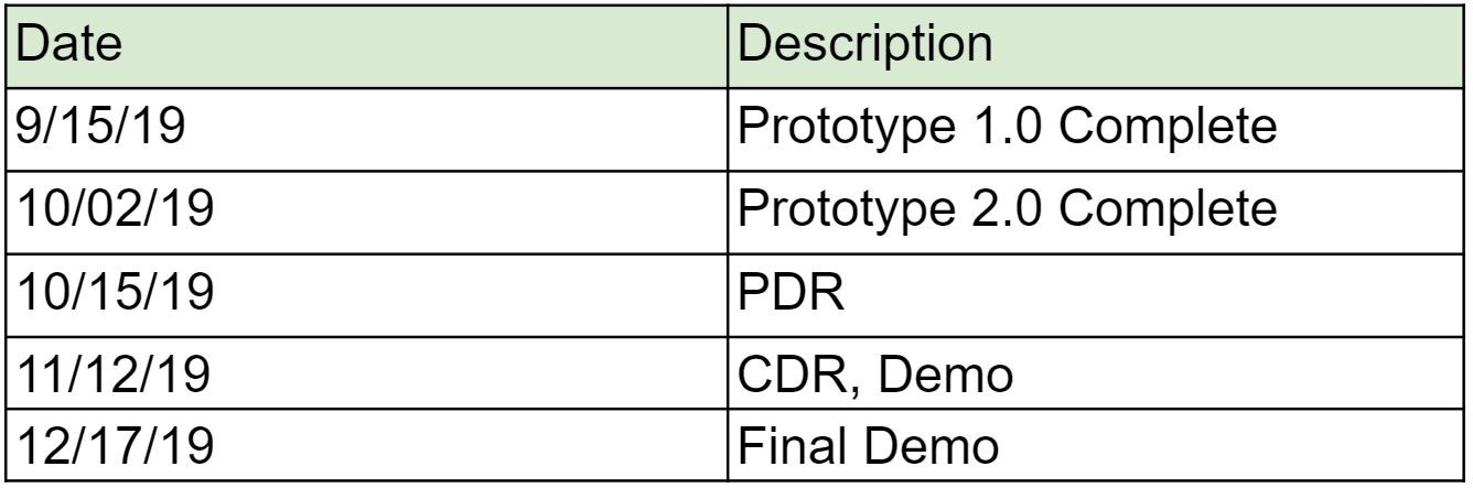
Figure 39. Waterfall Diagram