Fall 2016 Prosthetic Hand: PCB Schematic
Electronics and Control Engineer – Younis Al-Kharusi
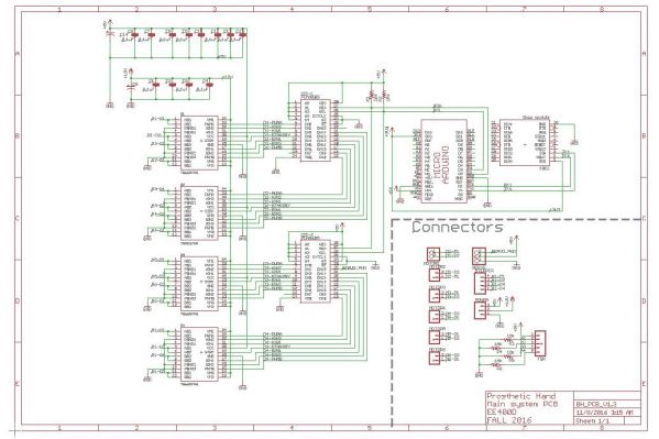
Above is the Custom PCB schematic, designed using EagleCAD.
The PCB consists of four (TB6612FNG) dual motor drivers that are capable of driving eight DC motors or four Stepper motors. TB6612FNG motor drivers are controlled by an Arduino micro through I2C using two (PCA9685) I2C controlled 16-channel PWM. In addition, the PCB has headers to mount both the Arduino micro and an XBEE module for Bluetooth communication.
JST connectors are used for DC motors, Stepper motor, servos and FSR sensors to ensure that connectors will not pop out during the rotation of the wrist. Screw terminal blocks are used for power connection coming from the Prosthetic Arm system. Additionally, male headers are used for available Arduino pins and for three extra I2C PWM channels.

