By: Brandon Perez (Missions, Systems, and Test)
Approved by: Ijya Karki (Project Manager)
| Req. No. |
“The Biped Shall” Statement |
Success Criteria |
Method |
Results |
Pass / Fail |
Introduction
This report covers the Test Plans for Verifying and Validating our Requirements.
Matrix
| L1-1 |
Shall be ready to participate in the game “Save The Human” on December 14th, 2016. |
The project must be fully functional and presentable by December 14th, 2016. |
Demo |
|
FAIL |
| L1-2 |
Shall not exceed a cost of $125.00 to construct. |
The project must not exceed a budget of $125.00. |
Inspect |
|
PASS |
| L1-3 |
Will use a 3Dot board, have a custom PCB, and utilize the I2C interface. |
The project must contain a 3Dot board as the main control unit for the system, have a custom-built PCB, and utilize the I2C interface on the 3Dot board. |
Inspect |
|
PASS |
| L1-4 |
Shall be able to walk a minimum speed of 0.32mm/sec. |
The Biped shall have to walk a straight path at a speed of 0.32mm per second. |
Test |
|
FAIL |
| L1-5 |
Shall be able to turn up to 180 degrees on each of its sides. |
When the Biped is initiating a turn, the angle that it turns its body shall be any angle ranging from 0-180 degrees. |
Test |
|
PASS |
| L1-6 |
Shall be controlled telepathically up to 20ft away through the Arxterra App. |
When controlling the Biped via Arxterra Control Panel on a mobile device, the Biped shall be able to be controlled up to 20ft away from the user. |
Test |
|
PASS |
| L1-7 |
Will have a mass less than or equal to 750 grams. |
The total Biped’s mass shall not exceed 750 grams. |
Test |
|
PASS |
| L1-8 |
Shall be able to operate for a minimum duration of 1.00 hour. |
The Biped system shall have to operate for a minimum duration of 1.00 hour |
Test |
|
PASS |
| L1-9 |
Should be able to walk on angled surfaces with max slope of (+/-) 6.5 degrees. |
The Biped should be able to walk on inclines of 6.5-degree slope and declines of -6.5-degree slope. |
Test |
|
FAIL |
| L1-10 |
Should be able to walk on uneven surface heights of 0.5 cm or less. |
The Biped shall remain stable when walking over obstacles spread over the ground which shall have heights ranging from 0 mm to 5 mm. |
Test |
|
FAIL |
| L2-1 |
Will have a DC motor that can operate effectively at 5V and produce torque of 9.75e-3 ft*lbs. |
The DC Motor shall have an operating voltage of 5V or greater and shall have to produce a minimum torque of 9.75×10^-3 ft*lbs. |
Test |
|
PASS |
| L2-2 |
Will have servos that can operate effectively at 5V and horizontally move a mass of 68g. |
The servos being used to control the Bipeds arms shall have an operating voltage of 5V or greater and shall be able to turn horizontally the Biped’s arm’s mass of 80g. |
Test |
|
PASS |
| L2-3 |
Will have a rotary encoder to read the shaft’s position at a rate of 40 times the Motor RPM. |
The shaft encoder shall give a reading of the shafts position at a minimum rate of 40x[Motor RPM] to ensure the MPU has a resolution |
Test |
|
PASS |
| L2-4 |
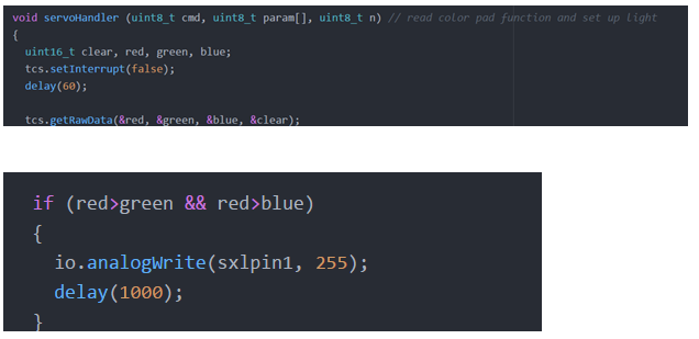
Shall use an RGB LED to display the color of the color pad for a minute duration. |
When the Biped steps on top of the color pads, the color of the pads shall be displayed on the RGB LED for a minute duration. |
Test |
|
PASS |
| L2-5 |
Should have an IMU to detect inclines and decline angle deviations up to (+/-)6.5 degrees. |
The IMU should provide readings of the angle deviation when the Biped is walking on angled surfaces for all angles between -6.5 and 6.5 degrees. |
Test |
|
FAIL |
| L2-6 |
Will use a battery with a capacity rated at 560mAh or greater. |
The battery for the system must be rated at a capacity of 560mAh or greater. |
Inspect |
|
PASS |
Level 1 Requirement 1:
Shall be ready to participate in the game “Save The Human” on December 14th, 2016.
Tools:
- Biped (final product)
- Calendar
- Clock
Procedure:
- If the Biped is complete, look at the calendar and record the current date.
- Look at the clock, and record the current time.
- Verify that the current time and date is before 9:30AM December 14th, 2016
RESULTS: By the time of final demonstration, the Biped was not able to walk. Our DC Motor Gearbox had gears that would constantly slip against each other causing our walk movement to stall at most times. In result, we did not meet the schedule requirement.

Level 1 Requirement 2:
Shall not exceed a cost of $125.00 to construct.
Tools:
- Biped Expense Report
Procedure:
- Look at the expense report and record the total Biped expenditure.
- Verify that total expenditure does not exceed $125.00.
RESULTS:

We have totaled $129.05 of expenses so we are $4.05 over budget. Regardless that we are over budget, we have still been within the customer’s contingency which is a reasonable 3.2% over budget.

Level 1 Requirement 3:
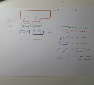
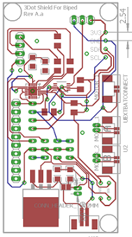
Will use a 3Dot board, have a custom PCB, and utilize the I2C interface.
Tools:
- Biped (final product)
Procedure:
- Inspect the Biped to verify a 3Dot board is being used when operated.
- Inspect the Biped to verify a custom-built PCB is being used when operated.
- Inspect the Biped to verify the I2C peripheral interface is being used when operated.
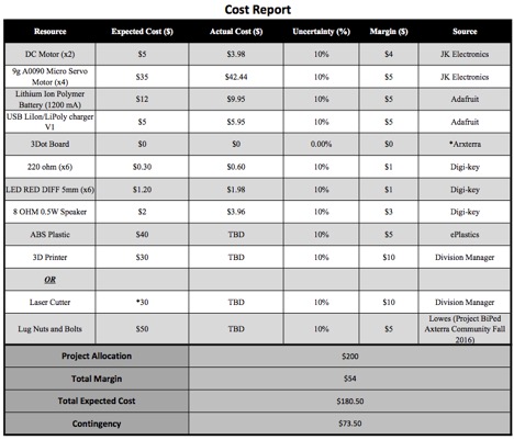
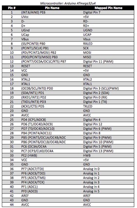
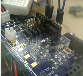
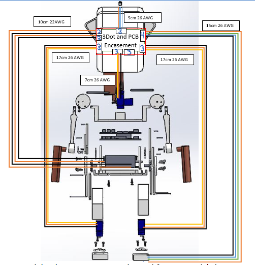
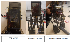
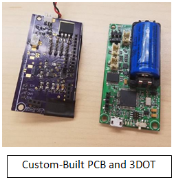
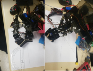
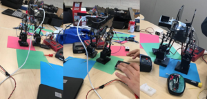
RESULTS: In the 3 pictures, below, we show 3 different perspectives of the of the 3DOT board and PCB encasement in our Biped.
The 3Dot’s board 12C peripheral interface pins are mapped to the custom built PCB for I/O access. Since we have a 3Dot board, a custom-built PCB, and are utilizing the I2C interface, this requirement has been met.
In the 3 pictures, below, we show 3 different perspectives of the of the 3DOT board and PCB encasement in our Biped. The 3Dot’s board 12C peripheral interface pins are mapped to the custom built PCB for I/O access. Since we have a 3Dot board, a custom-built PCB, and are utilizing the I2C interface, this requirement has been met.
Level 1 Requirement 4:
Shall be able to walk a speed of 0.32mm /sec.
Tools:
- Stop watch
- Measuring tape
- Biped with Arxterra Control
- Poster paper 3’x3’
- Marker
- String
Procedure:
- Mark the center point on the poster with the marker.
- Draw a circle of radius of 1ft around the center point using the string.
- Draw a radius on the circle.
- Place the Biped on the center mark made in step 1 facing the direction of the radius.
- Start a timer on the stopwatch and have the Biped operate its walking motion until it walks outside the circle and then stop the timer.
- Record the time it took for the Biped to reach outside the circle.
- Use V=D/T to determine the speed.
- Measure the angle at which the Biped walked with respect to the expected path to determine how straight the Biped walked.
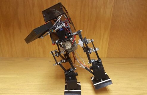
RESULTS: Unfortunately, our Biped was unable to walk without falling over. To point out the obvious issues, too much mass had been concentrated in the front of the Biped which caused it to fall frontward. For improvement up our design, we should extend the feet out by about 1cm.
Level 1 Requirement 5:
Shall be able to turn 180 degrees on each of its sides.
Tools:
- Protractor
- 8”x11” white paper
- Marker
- Biped with Arxterra Control
Procedure:
- Place the Biped on top of the center of the White 8”x11” sheet of paper.
- Use the marker to draw a line directly out from where the Biped is facing on the white sheet of paper.
- Initiate the Biped to turn at angles ranging from 30 to 180 degrees in increments of 30 degrees. With each new turn, the Biped should be replaced facing its original direction.
- With each turn implemented, draw lines out from where the Biped is facing on the paper when it is in its new facing position.
- Determine how accurately the Biped performed the turns by measuring the angles of each of the lines with respect to the original position.
RESULTS:
We began this test by initiating a turn on the Biped when it was standing on one leg.
The Biped was able to take a turn here of 44 degrees when standing on one leg. The turning requirement was set to be accomplished when walking, however we were able to independently turn without ever be in the walking motion, therefore this requirement has been met to some degree of turning, literally.
Level 1 Requirement 6:
Shall be controlled in RC mode in the Arxterra App up to 20ft away.
Tools:
- Measuring Tape
- Biped with Arxterra Control Panel on Mobile Device
Procedure
- Start the experiment by initiating a custom command to the Biped at 2ft away.
- Make sure no obstacles are in the way when sending commands and repeat the process by moving 2ft further each time until the Biped does not respond to the commands being sent.
- Record the distance at which the Biped did not respond to the commands from the mobile device.
- Verify that the distance recorded is greater or equal to 20ft.
RESULTS:
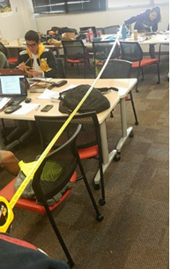
We began this test by setting up the Biped 20ft away from the user who was sending commands via Arxterra control.

Due to limited time, we had only tested directly above 20ft away. In the picture you can see the view of a tape measure being extended out to confirm we were at least 20 ft away from the Biped to meet the RC Mode requirement. We could confirm that our biped was still able to receive commands at 20ft away, therefore we met this requirement.
Level 1 Requirement 7:
Will have a mass less than or equal to 750 grams.
Tools:
- Scale with accuracy of (+/-) 0.5g
- Biped
Procedure:
- Turn on the scale and set the reading value to grams (g).
- Place the Biped on the scale and read the value of the mass.
- Verify the mass does not exceed 750g.
RESULTS:
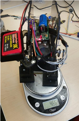
We begin by setting our Biped on the scale to determine its final mass.

The mass of the Biped is measured to be 466 grams. The mass requirement for our Biped is to be less than or equal to 750 grams, therefore this requirement has been met.

Level 1 Requirement 8:
Shall be able to operate for a minimum duration of 1 hour.
Tools:
- Biped
- Multimeter with current reading
Procedure:
- Measure the current drawn from the battery when the Biped is walking for the course of a minute.
- Determine the average current drawn from the battery over the minute duration.
- Verify that this value does not exceed the mAh rating on the system’s battery.
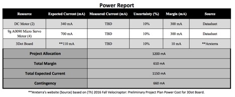
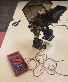
RESULTS: We begin the test by measuring the current drawn from the battery when the Biped is running the motor to produce its walking motion. We use an ammeter in series with the battery terminal and the DC motor pin. We recorded a video for a minute duration and then extracted the values from the ammeter throughout the video and provided them below.
We begin the test by measuring the current drawn from the battery when the Biped is running the motor to produce its walking motion. We use an ammeter in series with the battery terminal and the DC motor pin. We recorded a video for a minute duration and then extracted the values from the ammeter throughout the video and provided them below.
Data Collected from Ammeter: [0.68 0.14 0.12 0.14 0.10 0.19 0.09 0.37 0.33 0.93 0.47 0.48 0.38 0.35 0.44 0.41 0.45 0.40 0.47 0.33 0.42 0.61 0.57 0.42 0.37 0.88 0.39 0.53 0.64 0.87 1.14 0.98 0.64 0.82 0.46 0.48 0.29 0.33 0.58 0.41 0.55 0.39 0.50 0.56 0.72 0.90 0.40 0.60 0.49 0.71 0.40 0.66 1.21 0.75 0.34 0.39 0.52 0.35 0.36 0.98 0.42 0.54 0.54 0.51 0.71 0.72 0.76 0.96 0.78 0.51 0.59 0.34 0.31 0.26 0.62 0.33 0.20 0.28 0.25 0.20 0.42 0.51 0.62 0.61 0.43 0.57 0.66 0.45 0.36 0.52 0.42 0.38 0.45 0.32 0.18 0.22 0.28 0.32 0.20 0.41 0.37 0.48 0.52 0.58 0.27 0.29 0.35 0.27 0.14 0.22 0.19 0.16 0.13 0.20 0.21 0.29 0.40 0.55 0.46 0.55 0.48 0.46 0.40 0.34 0.23 0.25 0.35 0.37 0.25 0.30 0.24 0.35 0.31 0.29 0.49 0.54 0.48 0.56 0.62 0.38 0.24 0.19 0.15 0.25 0.28]
I then proceeded to calculate the average in MATLAB.
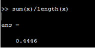
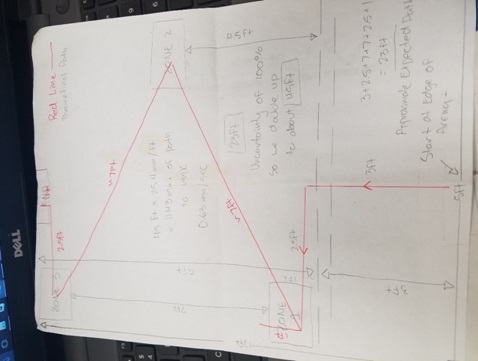
Since our walking motion is our most energy expensive operation, we can assume that we walk the entire duration of the game to get the maximum energy expense throughout the entire game duration.
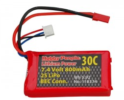
If we assume the Biped will be walking the entire game, (which in reality, it won’t) it would consume 440mA x 1hr = 440 mAh of energy from the battery. Since our battery can provide 800 mAh of energy theoretically, then our battery should have sufficient energy for providing power to the Biped for the entire game duration of an hour.
Level 1 Requirement 9:
Should be able to walk on angled surfaces with max slope of (+/-) 6.5 degrees.
Tools:
- Biped with Arxterra Control (final product)
- Ramp of 6.5 degrees
Procedure:
- Operate the Biped and have it walk up against the incline and verify it doesn’t fall over.
- Operate the Biped and have it walk down the incline (decline) and verify it doesn’t fall over.
RESULTS: Unfortunately, our testing and design had been narrowed and focused towards the walking portion of the design, so we disregarded testing on inclines.
Level 1 Requirement 10:
Should be able to walk on uneven surface heights of 0.5 cm or less.
Tools:
- Biped with Arxterra Control (final product)
- Cardboard cutout 6”x6” of 0.5 cm thickness
Procedure:
- Place the Biped on the floor.
- Place the carboard cutout a couple of inches away from the Biped.
- Operate the Biped and have it walk towards the cutout.
- Verify that the Biped can walk over the cardboard cutout without falling over.
RESULTS: Unfortunately, our testing and design had been narrowed and focused towards the walking portion of the design, so we disregarded testing walking on uneven surfaces.
Level 2 Requirement 1:
Will have a DC motor that can operate effectively at 5V and produce torque of 9.75e-3 ft*lbs.
Tools:
- DC Motor
- String
- Water bottle
- Scale
- Ruler
Procedure:
- Measure the shaft Radius for the DC Motor being used on the Biped.
- Divide the torque required [9.75×10^-3 ft*lbs] by the obtained shaft radius to get the weight.
- Fill the water bottle with water till it weighs as much as the value obtained in step 2.
- Tie the string several times around the motor shaft until it does not slip off.
- Tie the other end of the string the water bottle.
- Power the DC motor against the edge of a table with the water bottle hanging from the shaft.
- Verify that the motor can lift the water bottle.
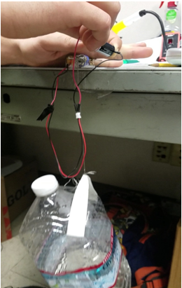
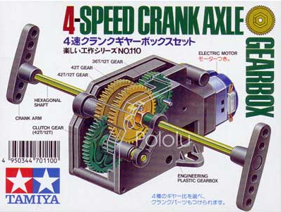
RESULTS: We have set our DC motor torque requirement in the units of ft*lbs for making our calculation easier. We proceed to measure the diameter of our motor shaft to determine its radius.
We used calipers to measure the DC Motor shaft diameter.

T = F*L
T = 9.75×10^-3 ft*lbs
L = 2.6mm/2 = 1.3mm
1.3mm = 0.0043 in
F = (9.75×10^-3 ft*lbs)/(4.3×10^-3 ft) = 2.26 lbs = 36.28 oz
Since our DC Motor is already rated at 5V, no test must be done for the first part of the requirement. As far as the torque requirement, the DC Motor was successfully able to lift the gallon of water up, therefore this requirement has been met.

Level 2 Requirement 2:
Will have servo that can operate effectively at 5V and horizontally move a mass of 68g.
Tools:
- Servos being used to control the Biped’s arms
- Servo shaft connector piece
- Small tray 3” diameter
- Water Bottle
Procedure:
- Place the servo with the shaft axis facing upright.
- Attach the servo shaft connector and place the tray on top of the connector.
- Make sure the tray is secure on top of the servo’s connector.
- Fill the water bottle until it weighs 68g.
- Place the water bottle on top of the tray.
- Operate the servo and verify that it can turn over its full range while having the mass over it.
RESULTS:
Since our servo is rated at 5V already, no test is necessary for the first part of the requirement. To check if our servo can horizontally move a mass of 68g, we set the servo upright and attach a platform to carry the several different masses.

It was found through this experiment that the servo could horizontally move the masses on top of the platform up to 400g. We concluded that we that servo could meet the requirement so we suspended further testing of heavier masses.

Level 2 Requirement 3:
Will have a rotary encoder to read the shaft’s position at a rate of 40 times the Motor RPM.
Tools:
- 3Dot Board
- Rotary Encoder interfaced onto the 3Dot board
- Rotary Encoder test code
Procedure:
- Run the test code for the rotary encoder.
- Be sure to have a serial communication from the 3Dot board to your computer to see the sensor values.
- Turn the potentiometer of the rotary encoder and verify that the sensor can read values at various positions.
RESULTS:
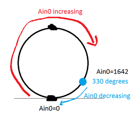
We began this test by timing how long it too our motor to turn its shaft a full 360 degrees under the load of the legs it must move.
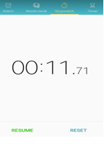
Time per motor revolution: 11.71sec
MOTOR RPM = (60secs per min)/(11.71sec) = 5.12
Therefore, our rotary encoder must read values at a rate of 40×5.12 = 204.8 times/minute to get a sufficient resolution of the shaft position.
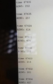
We then began to try and measure how fast our rotary encoder could take values so wrote an Arduino code to write a timestamp after every rotary encoder reading.
Our values being outputted at the computer for time are in units of milliseconds. If you look at the picture at the left, you can see that each of the time readings are spaced by 4 milliseconds.
Therefore the sample rate for our rotary encoders ADC is 60/(4×10^-3 Hz) = 15,000 times per minute.
This sample rate is clearly sufficient for our system, therefore this requirement is met.
Level 2 Requirement 4:
Shall use an RGB LED to display the color of the color pad for a minute duration.
Tools:
- 3Dot Board
- Color Senor interfaced with 3Dot board
- Color sensor test code
- RGB LED
- Red, blue, and green construction paper
Procedure:
- Interface the Color Sensor and the RGB LED with 3Dot board.
- Run the test code for the color sensor and have the sensor readings output to the RGB LED.
- Place the red construction paper near the color sensor and verify the LED lights up red.
- Place the blue construction paper near the color sensor and verify the LED lights up blue.
- Place the green construction paper near the color sensor and verify the LED lights up green.
RESULTS:
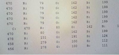
We began testing the color sensor by seeing if our sensor was reading values. We placed the Biped above 3 different colored construction papers of color red, blue, and green.
The above pictures show our Biped testing the color sensor on the foot. To determine if our color sensor was reading the values, we send the sensor values via seirial communciation to be displayed on our computer.
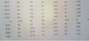
We were able to successfully distinguish the color of the construction with the data we were receiving on our monitor. Our color sesnor was sucessful, however we were not able to display the value on the RGB LED since our GPIO expander on our custom PCB was having issues.
Level 2 Requirement 5:
Should have an IMU to detect inclines and decline angle deviations up to (+/-)6.5 degrees.
Tools:
- 3Dot Board
- IMU
- IMU Test Code
Procedure:
- Interface the IMU with the 3Dot through the I2C peripheral interface.
- Run Test code for the IMU on the 3Dot.
- Be sure to have a serial communication from the 3Dot board to your computer to see the sensor values.
- Once code is running, tilt the sensor at various angles.
- Verify that the sensor responds well to all angles being tilted at.
RESULTS: Due to limited time, we decided to not include an IMU in our final design since it would require more testing and its effectives would only benefit us if our system had already passed walking.
Level 2 Requirement 6:
Will use a battery with a capacity rated at 560mAh or greater.
Tools:
- Battery being used for Biped
Procedure:
- Identify the Capacity in mAh for the battery being used on the Biped
- Verify that the batteries capacity exceeds 560 mAh.
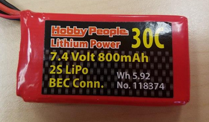
RESULTS:

Our battery is rated at 800 mAh, therefore this requirement has been met.