

The custom printed circuit board was designed to include both the gyro sensor and the LED display on the top panel. The LED will display the direction the tank is taking within the maze. By working with my project and division manager the schematic and layout were created on Eagle CAD. The files were not […]

The goal of this guide is to provide setup for the custom commands needed on the Arxterra APP side in order to control the Goliath running the final code. Secondly, this guide will provide instructions on how to control the goliath correctly from the commands defined.

Based on our L1 requirements to have a LED display and the L2 sub-requirements to indicate the next turn direction, having an LED grid display was a stretch goal. After some (what turned out to be pretty simple work) the LED proves very useful in indicating to the user the intended direction when user input is […]
Written by Charles Banuelos(Division Manager Design and Manufacturing) & Muhannad Al Mohamed(Division Manager E&C)
Approved by Charles Banuelos(Division Manager Design and Manufacturing), Muhannad Al Mohamed(Division Manager E&C), Mark Huffman(Project Manager Goliath), Zach Oyog (E&C Sojourner)
Fabrication of the 3DoT IR shield occurred on 12/5/2017 due to the fact that Color Sensor Shield fabrication was not able to be completed. There was no stencil available to use to solder the IR shield; therefore, hand soldering is needed. The IR sensors themselves where placed flushed to the board to ensure that the IR sensors do not come contact the ground during the mission.
The fabrication process did have some setbacks while soldering parts. The first major set back was placing the surface mount parts on top of the IR shield without using the pick and place machine. The lack of the pick and place machine caused many dead joints at surface mount parts due to improper placement. The other setback was the actual look of the solder themselves and many needed to be redone due to none uniformity.
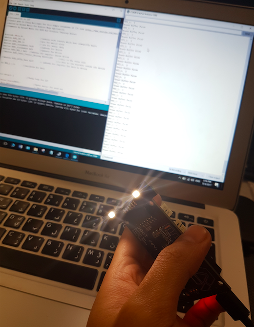
Testing the IR shield was done by applying an Arduino code to it. Since the IR shield uses the six pins of the front header of the 3DoT board (A2,A3,SDA,SCL,3.3V VCC,GND), the code optimizes direct reading from the pins using Arduino’s built in read function. The used code was applied to a 3Dot board to ensure a proper running of the sensors. The test revealed that we were successful on fabricating four shields out of five. The fifth IR shield will be taken back to fab to ensure that all are working.

Placing components during Fabrication of the IR sensor shield
The following code is used to test the distance measurement for each IR ICon the 3DoT IR shield.
The following code was altered by changing the reading commands from “analogRead” to “digitalRead.” The reason for this change was because the SDA and SCL pins are not actually analog pins, thus, the function “analogRead” would not return actual measurements. Therefore, the command “digitalRead” was used instead to get binary inputs as an indication that the pins are actually working.
Code :
////////////////////////////////////////////////////////////////
//  Name     : 400D IR Shield Testing Code                    //
//  Author   : Muhannad Al Mohamed                            //
//  Date     : 5 December, 2017                               //
////////////////////////////////////////////////////////////////

 //defining variables to save measurements
 int farRight_IR;
 int innerRight_IR;
 int innerLeft_IR;
 int farLeft_IR;

 void setup()
 {

   Serial.begin(9600);

   pinMode(A3,INPUT);      //Top view, pins up, far right IR sensor
   pinMode(SDA,INPUT);     //Top view, pins up, second right IR sensor
   pinMode(SCL,INPUT);     //Top view, pins up, second left IR sensor
   pinMode(A2,INPUT);      //Top view, pins up, far left IR sensor

 }

 void loop()
 {

  //reading values of IR sensing into variables
  farRight_IR = digitalRead(A3);
  innerRight_IR = digitalRead(SDA);
  innerLeft_IR = digitalRead(SCL);
  farLeft_IR = digitalRead(A2);

  //printing measurments in searial monitor
  Serial.print("farRight_IR =  ");
  Serial.print(farRight_IR);
  Serial.print("  ");
  Serial.print("innerRight_IR = ");
  Serial.print(innerRight_IR);
  Serial.print("  ");
  Serial.print("innerLeft_IR = ");
  Serial.print(innerLeft_IR);
  Serial.print("  ");
  Serial.print("farLeft_IR = ");
  Serial.println(farLeft_IR);


  delay(250);
 }
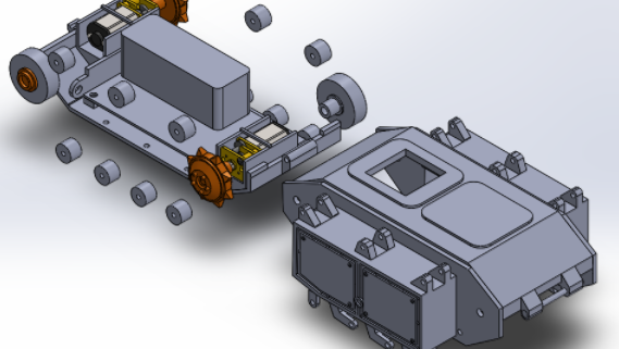
After taking a closer look at the IR sensor, I realized that the sensor needed to be relocated to avoid contact with the first motor. The distance between the top panel and the front motor is not large enough to fit the sensor. Although we did consider redesigning the top, the tank will lose its […]

1. Project Schedule – Project shall be ready by Wednesday, December 13th, 2017 2. Operational Task – The Goliath will have the functionality to be connected remotely using Arxterra 3. Toy – Elements – The Goliath will behave like a toy 4. Driving Surface – The Goliath will be able to drive on flat surfaces 5. Driving Surface – The Goliath shall […]
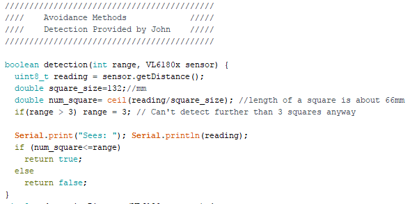
Detection is a subroutine used in the collusion protocol. The subfunction will employ an IR proximity sensor, VL6180. The distance outputted will be converted to a discrete value called squares which are dependent on the measured squares from the physical maze. Each side of the square is roughly 6.6 cms long meaning we have a […]
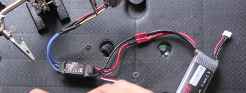
The purpose of this post is to relay and archive the results the Mock-up Motor specific testing. The measured results are the speed and the current draw. The Goliath will use 2 micro motor gear. It is also subject to a weight load of about 190 grams. This experiment was tested on a carpet surface.
Approved By: Muhannad Al Mohamed, Charles Banuelos, Melwin Pakpahan
Written By: Muhannad Al Mohamed
Table of Contents
The parts used in the fabrication of each color sensor shields are the printed circuit board, electronic parts(two color sensors (BH1745NUC-E2), two LEDs (0603 package), two 150 Ohms resistors (0603 package), one 10k resistor (0603 package), one 47k resistor (0603 package), two 0.1 uF capacitors (0603 package), one MOSFET, one pin header), and Color Sensor Shield’s stencils along with solder.
The design of the Color Sensor Shield is done using the free EagleCAD software. The schematics file of the circuit is attached to this link. The Printed Circuit Board layout is attached to this link. To open files the EagleCAD software needs to be installed.
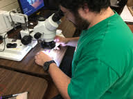
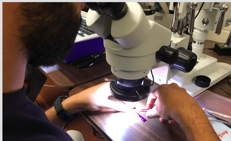
The fabrication of the CSS (Color Sensor Shield) is currently taking place in ET-111 room. The room is equipped with a microscope that can help in placing the parts on the shield. It also has an oven that can be used to melt the solder on the shield to hold the solder in place. Other useful amenities are available in the room such as a fridge to keep the solder cooled and ready to be used, and scissors and tape that can be used to hold the shield in one spot to place parts.
The fabrication process starts with holding the shield in one place and apply solder to it. Some unused PCBs are used to hold the shield in the center with duck tape applied to it.
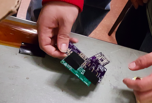
Placing CSS in the centre of other PCBs to hold it
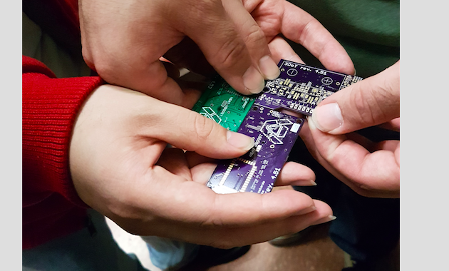
Solder is then placed on the board with a stencil on top of it using a card to evenly spread the solder. The microscope is then used to check if enough solder is applied to the PCB’s pads. Parts are then placed on the shield using tweezers to carefully put each part on the exact corresponding place.
Placing parts using tweezers
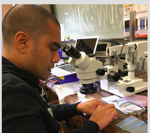
Checking if parts placed correctly
After making sure that the parts are placed on the correct place by looking at the shield through the microscope, the shield is then placed in the oven to let the solder flow and melt to make the connection to the parts.
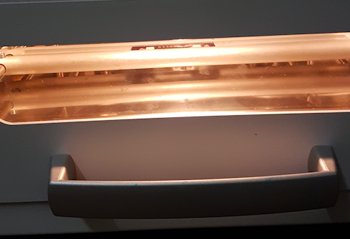
Cooking the CSS in the oven
Since the CSS has parts placed on the top and bottom of it, only one side, of the shield, parts will be placed on put in the oven. The other parts on the other side will be placed and soldered by hand.
Update: 12/6/2017
We were able to fabricate four shields with the parts provided.
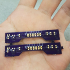
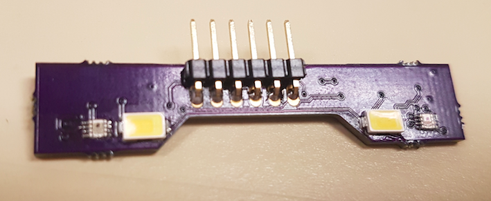
Color Sensor Shield Top View
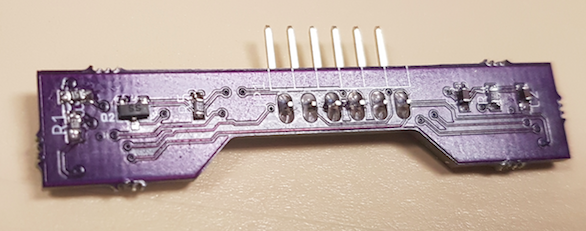
Color Sensor Shield Bottom View
The CSS will be tested once a fabrication of on shield is done. The shield will be connected to a 3DoT board and the I2C addresses would be checked. Codes of reading values within the registers in the Color Sensor IC should be applied to CSS through programming the 3DoT board.
The first test on the shields was an inspection to locate any bridges present on the surface mount pads or dislocation of parts. If any bridges or dislocation are present, the shields would be fixed by desoldering the parts with a heat gun and soldering them again in place. By visual testing, we found that two shields had their LEDs light on and the other two were not functioning. Therefore, pin testing was done to check if the LEDs and the Color Sensor ICs had power in them. Surprisingly all the pins had power in them, therefore, any misfunctions could not be seen visually.
After checking that all parts are in place, the address checking code is applied to the Color Sensor Shield to make sure that the two sensors have the addresses of (0x38) and (0x39).
Another testing method to see if the Color Sensor Shields are actually working is by applying an Arduino code that uses the I2C library to read data from a register within the Color Sensor IC. The code attached reads data from the register that holds the value of the Red color.
Reading data from a register on the Color Sensor
This code was unable to read data from the Color Sensor Shield so another code is used. This code is optimized to measure colors from the color sensor shield.
The measurements taken was applied by using a green surface with different locations.
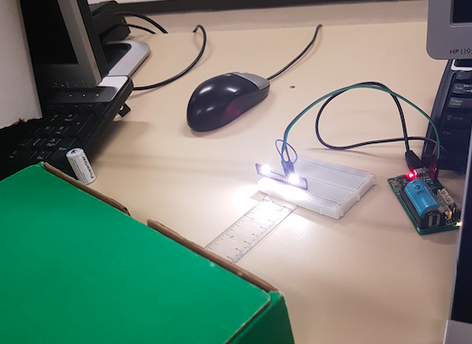
Taking measurements of the color sensor shield
Perpendicular alignment of the measured surface to the color sensor shield
Horizontal alignment of the measured surface to the color sensor shield
After taking measurements, we have concluded that the furthest distance for the color sensor to sense colors are 2cm perpendicularly and 0.5cm horizontally.
After testing all Color Sensor Shields (CSS), there were no functional shields that can be accurately used to take measurements of colors in the maze. Two of the shields did not have a functional LEDs due to the burning of some parts during fabrication. The other two boards had functional LED but only one color sensor on one board was functional. The other color sensor on that board was intermittent and could not be relied upon for accurate measurements.
The possible reasons for the failure of producing functional Color Sensor Shields are solder bridges created during the soldering process and burnt parts during the repair process. The bridges could have been created during the placement of the parts on the board which was done by hand instead of using the pick and place machine or during the baking process to solder the parts to the board. The burning of extra parts occurred during the repair of certain parts that did not solder to the board. A heat gun had to be used to repair the boards which would cause surface burns and ultimate destruction of parts.