By: Tae Min Lee (Missions, Systems, and Testing Engineer)
We have to make sure that the level 1 requirement for safety has been addressed before we start implementing the laser tag system we will be using for our product.
Problem:
The first design of implementing the laser tag game was to use a laser module with a photo resistor as the receiver. However, it became a problem with making the product safe for children to play with due to the following:
Laser was classified as level 2
Class 2 – lasers emit radiation in the visible portion of the spectrum, and protection is normally afforded by the normal human aversion response (blink reflex) to bright radiant sources. They may be hazardous if viewed directly for extended periods of time. Ex: Laser Pointer
Most laser module power rating are 5mW, but to be considered safe it must be 1mW to be classified as level 1.
Class 1 – lasers are considered to be incapable of producing damaging radiation levels, and are therefore exempt from most control measures or other forms of surveillance.
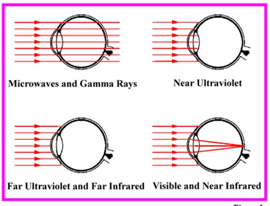
Lasers are concentrated beams (visible) that passes through the cornea and focuses on one point on the back of the retina (shown in figure 1).
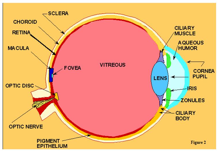
The concentrated laser beam cause damage to the cornea, retina, and the lens (figure 2).
Visible (400 – 760 nm Wavelength)
Most of the radiation is transmitted to the retina.
Overexposure may cause flash blindness or retinal burns
Quick Calculation of the magnification of the damage to the eye:
Conclusion: Laser retinal injury can be severe because of the focal magnification making it dangerous to implement a laser module for the laser tag game.
Solution:
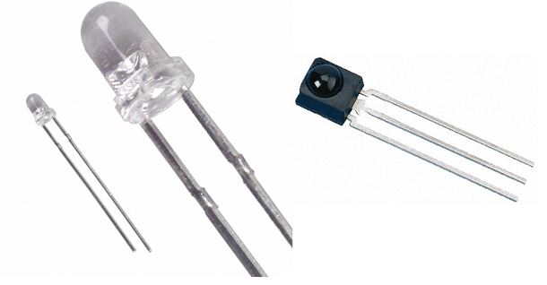
To make a product that is safe for children to play with we implemented the use of IR LED emitter for the laser tag game. The safety requirements for the Goliath using IR emitter will be stated below:
Emitter must not produce enough radiation that brings harm to the eyes
Emitter will not produce a highly concentrated beams that will damage the retina (figure 1).
IR LED is non-visible light that doesn’t pass the cornea making it safe
https://www.arxterra.com/wp-content/uploads/2016/03/feature-image-second.jpg542484refaas0a/wp-content/uploads/2013/04/Arxterra-Logo-340x156.pngrefaas0a2016-03-14 22:25:562018-03-08 21:37:07Spring 2016 3 DOT Goliath Laser Tag Game Safety Requirements for Children
By: : Tae Min Lee (Missions, Systems, and Testing Engineer)
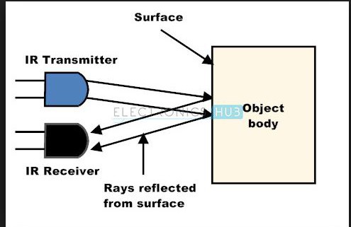
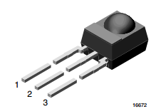
IR Mid-Range Proximity Sensor
Implementing a game of laser tag using IR emitter/receiver will be safe for to play for all ages. This falls back to one of our level 1 requirements for safety standards for child safe toys. The figure above shows the connections for the sensor for the following:
Output
Ground
Vcc
Components Used:
Arudino Uno
IR LED (Remote Control)
x3 Red LED
BreadBoard
Wiring Kit
x2 220 ohm resistor
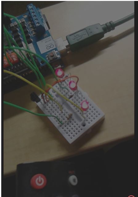
The affective distance of the detector and the IR LED was measured to be around 1.85 meters. The distance was determined by using a remote control that has a IR LED emitter that was aimed at the sensor. We had a red LED to detect when the IR sensor gets hit by the remote control. The laser tag game will have a rule for the first 3 hits will declare the winner (figure seen below).
https://www.arxterra.com/wp-content/uploads/2016/03/feature-image-3.jpg326495refaas0a/wp-content/uploads/2013/04/Arxterra-Logo-340x156.pngrefaas0a2016-03-14 22:16:442018-03-08 21:37:12Spring 2016 3 DOT Goliath IR Emitter/Receiver Test
By: Tae Min Lee (Mission, Systems, and Testing Engineer)
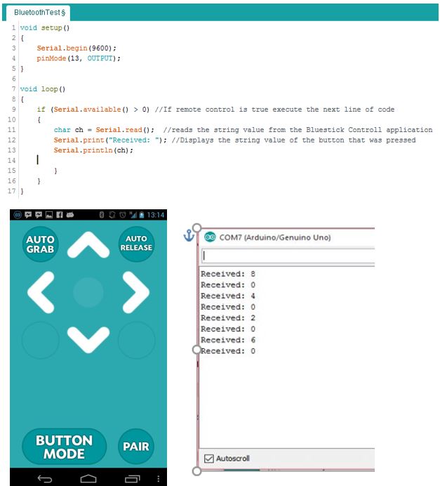
One of the requirements of the Goliath was using the Arxterra Control Panel and the Arxterra application. Since, the 3Dot board was not given at the time we had to find an alternative to test the Bluetooth module (HC-06). Before we start using the Arxterra application we performed a basic test on the Bluetooth module. The purpose of this test was to determine the communication between the Bluetooth module and the android device.
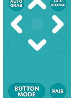
We used an android application called BlueStick Control on an android phone. The following code shown above was uploaded to the Arduino Uno along with the Bluetooth module. By pressing the up key the serial monitor returned a string value 8 corresponding to the key that was just pressed. The next string value 4 corresponds to left, string value 2 corresponds to down and string value 6 corresponds to right. The zero value shows the default string value it returns to as the user lets go of the key (shown above).
The tutorials to test the Bluetooth module came from instructables to test out the basic functions of a Bluetooth module. We performed a test of the code to see the communication between the Arduino Uno with the HC-06 Bluetooth module. We tested to determine the output interface for our lasers and motor control.
Components Used:
Bluetooth Module (HC-06)
Wiring Kit
Arduino Uno
Motor
Laser Module
Arduino IDE
Arduino Motor Shield
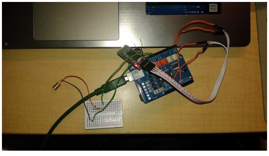
The following circuit shown below was used to test the laser shot control using an Arduino Uno, laser module, and the Bluetooth module.
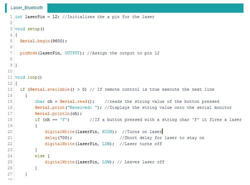
Modifying the code shown earlier we can control the laser shots by pressing a button from our android device that will be communicating with the Arduino Uno through a Bluetooth Module. See the following code:
The code will set the laserPin HIGH (turn on laser) when the button with the string character ‘F’ is pressed.
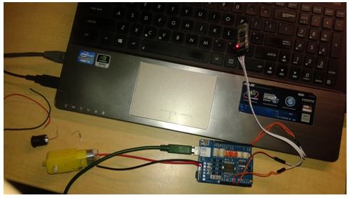
The next test was performed to see if the android device was able to communicate with the Bluetooth Module that was connected with both the Arduino Uno and the Arduino Motor Shield (shown below).
The following code will be used to implement the motor control that will be used on the Arduino Uno and the Arduino Motor Shield:
const int //Declaring all the pins used for motor 1 and motor 2
//Motor 1
PWM_A = 3,
DIR_A = 12,
BRAKE_A = 9,
SNS_A = A0,
//Motor 2
PWM_B = 11,
DIR_B = 13,
BRAKE_B = 8,
SNS_B = A1,
laser = 6;
void setup()
{
// Intializes the output and input for the pins
pinMode(BRAKE_A, OUTPUT);
pinMode(DIR_A, OUTPUT);
pinMode(BRAKE_B, OUTPUT);
pinMode(DIR_B, OUTPUT);
Serial.begin(9600);
}
void move()
{
digitalWrite(BRAKE_A, LOW); // settig the brake LOW to disable motor brake
digitalWrite(DIR_A, LOW); // now change the direction to forward setting LOW the DIR_A pin
analogWrite(PWM_A, 250);
digitalWrite(BRAKE_B, LOW); // now change the direction to forward setting LOW the DIR_B pin
digitalWrite(DIR_B, LOW);
analogWrite(PWM_B, 250);
}
void brake()
{
digitalWrite(BRAKE_A, HIGH); //Sets the brakes for both motor 1 and motor 2
digitalWrite(BRAKE_B, HIGH);
}
void backward()
{
digitalWrite(BRAKE_A, LOW); // setting againg the brake LOW to disable motor brake
digitalWrite(DIR_A, HIGH); // now change the direction to backward setting HIGH the DIR_A pin
analogWrite(PWM_A, 250);
digitalWrite(BRAKE_B, LOW); // setting againg the brake LOW to disable motor brake
digitalWrite(DIR_B, HIGH); // now change the direction to backward setting HIGH the DIR_A pin
analogWrite(PWM_B, 250);
}
void turnRight()
{
digitalWrite(BRAKE_A, LOW); // setting againg the brake LOW to disable motor brake
digitalWrite(DIR_A, HIGH); // now change the direction to backward setting HIGH the DIR_A pin
analogWrite(PWM_A, 250);
digitalWrite(BRAKE_B, LOW); // setting againg the brake LOW to disable motor brake
digitalWrite(DIR_B, LOW); // now change the direction to forward setting LOW the DIR_A pin
analogWrite(PWM_B, 250);
}
void turnLeft()
{
digitalWrite(BRAKE_A, LOW); // setting againg the brake LOW to disable motor brake
digitalWrite(DIR_A, LOW); // now change the direction to forward setting LOW the DIR_A pin
analogWrite(PWM_A, 250);
digitalWrite(BRAKE_B, LOW); // setting againg the brake LOW to disable motor brake
digitalWrite(DIR_B, HIGH); // now change the direction to backward setting HIGH the DIR_A pin
analogWrite(PWM_B, 250);
}
void stop()
{
digitalWrite(BRAKE_A, HIGH);
digitalWrite(BRAKE_B, HIGH);
}
void loop()
{
// put your main code here, to run repeatedly:
char ch = Serial.read();
Serial.print(“Received: “);
Serial.println(ch);
if (ch == ‘8’) //Move forward
{
move();
delay(1000);
stop();
}
}
The code shown above will only implement the move forward function by calling on the sub routine move. By adding else if statements we can implement a turn right, turn left, or backwards.
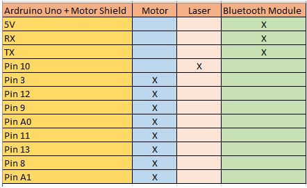
The overall pins that we will be using on the Arduino Uno is shown below:
By: Kevin Moran (Electronics and Control Engineer), Tae Lee ( Systems Engineer)
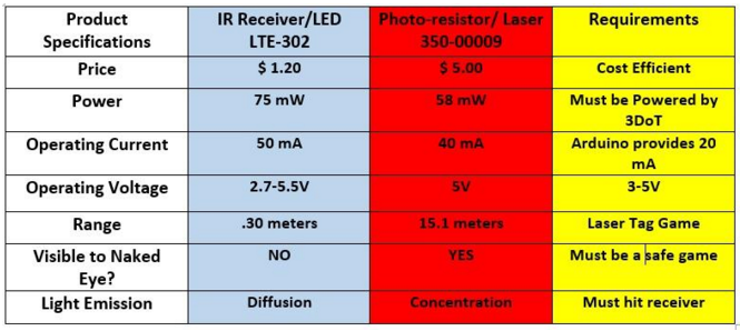
Our team’s mission is to decide the better approach for a game of laser tag, either by using lasers and light detecting sensors, or by using IR Receivers and LEDs. From the research we concluded on proceeding to test Photo-resistors and lasers for our game of game tag. The reason being that the laser has a longer range to activate the resistor, over 14 meters more than the IR that was tested. The laser can hit targets further, because the light emitted is concentrated on a single focus and wavelength (for the most part) and then transmitted. The IR LED diffuses its wavelength, sending it in all directions. In order to achieve this game using IR receivers, the range will have to be too short and the IR LED must be able to concentrate its light on the target. The laser requires less operating voltage than the IR receiver, and that is an advantage since we are trying to keep our current dissipation to a minimum.
The laser and photo-resistor were tested using an Arduino circuit, and the Plot function in order to observe its behavior in the presence of the laser and of natural light.
Laser test results:
When testing the laser and its receiver, it was necessary to ensure the photo-resistor would not activate under normal light conditions. When a laser light was not focused on the target, the graph showed a flat line very close to the zero value. When the laser was aimed, the graph peaked. It was noted that the peaks increased if the laser was aimed for a longer amount of time. 1 second provided us with the taller peaks in the graph. This analog signal we are obtaining must be converted to Digital in order for receiver to activate regardless of the amount of time the laser aims to it.
Recommendation:
If the laser is to be powered the 3DoT board, this board must be able to supply the 40 mA that the laser requires. When tested with and Arduino, it was noted that this board only provided an output of 20 mA. I recommend to either use a smaller laser that requires less than 20 mA to operate, or to build a PCB with a circuit regulator in order to ensure the laser works as it is intended.
https://www.arxterra.com/wp-content/uploads/2016/03/Screen-Shot-2016-03-07-at-7.46.58-PM.png298665refaas0a/wp-content/uploads/2013/04/Arxterra-Logo-340x156.pngrefaas0a2016-03-08 03:54:272018-03-08 21:37:20Spring 2016 3DOT Goliath Laser vs. IR LED Trade-Off Study
By: Kevin Moran (Electronics and Control Engineer)
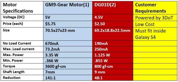
After carefully reviewing motors on the market, the two motors presented above were selected; the GM9-Gear and DG1D motors. These two motors are very easy to obtain and the price is within our cost margins. They require a voltage output that is within the capabilities of the 3DoT board to support. The preliminary design of the rover puts the mass at 680 grams. The specifications of motor DG1D is the best match for our level 1 and level 2 requirements. A level 1 requirement of having the rover be as small as an Android phone led to the selection of the Samsung Galaxy S4 size as the size of the body. This selection capped the mass of the rover at under 800 grams. Motor 2 has the torque required to power our rover, as opposed to Motor 1 whose torque is over 4 times the necessary amount. This torque forces Motor 2 to require 3 times more Wattage than Motor 1. With the Wattage that is being saved by selection Motor 2, we will be able to power the laser and receiver and consume less battery life. Motor 1 has a higher RPM value, and while our torque is sufficient to move our rover; this will give it a faster speed than Motor 2 will. The 3DoT board’s power is regulated and is stepped up from 3.7 V to 5.0 V (600 mA max) Voltage Booster (TI TPS61200) which will power the motors.
By the way, the 3DoT board uses Motor Driver – Dual TB6612FNG allowing us to independently control the two motors.
https://www.arxterra.com/wp-content/uploads/2016/03/motor-blog-pic.jpeg108144refaas0a/wp-content/uploads/2013/04/Arxterra-Logo-340x156.pngrefaas0a2016-03-08 03:43:472018-06-12 23:36:18Spring 2016 3DOT Goliath DC Motor Trade-Off Study
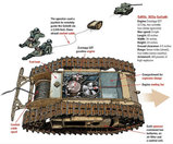
Inspired by the German Goliath, 3DOT Goliath is designed utilizing 3DOT board, with the minimum 3-D printing time. The 3-DOT Goliath will battle 3DOT Spider, tag battle, utilizing optical transmission and receiving device. The 3DOT should be controlled via live camera, periscope, on an Android phone.
REQUIREMENTS & VERIFICATION:
1- The 3DOT Goliath will be tested Monday, May 9, 2016, which is the final day of the class.
Verification: Spring 2016 Final day
2- Level 1 requirements stipulate that the total cost of 3DOT Goliath should not exceed $90.
Project vs Product’s budget: To document the difference between development cost and final product cost, the 3DoT Goliath must create a Project Budget and a Product Budget.”
3- When receiving 3 tags, the rover is disabled.
4- Inspired by German Goliath, robots with tracks.
5- Print time less than 6 hours.
Verification: level 1 requirements were updated during last week meeting with the customer.
In order to have a robot that meets all level 1 requirements, the 3DOT Goliath would use IR sensors and transmitters. A prototype version of the project will be built using legos and Arduino to test the sensors and transmitter functionality. For a wider field view angle, a fisheye periscope will be added to the phone camera.
Installing fisheye periscope – wider field view angle.
Neck- extended to provide a high vantage point on the top.
Step 3. Solution :
The customer will be given two options:
1- Basic level 1 requirements design with the minimum basic attributes.
2- In order to meet budget requirements, optional attributes with additional costs will be provided to customer.
3- Development budget will allocated to test additional attributes that will be added to the project.
Mechanical Design
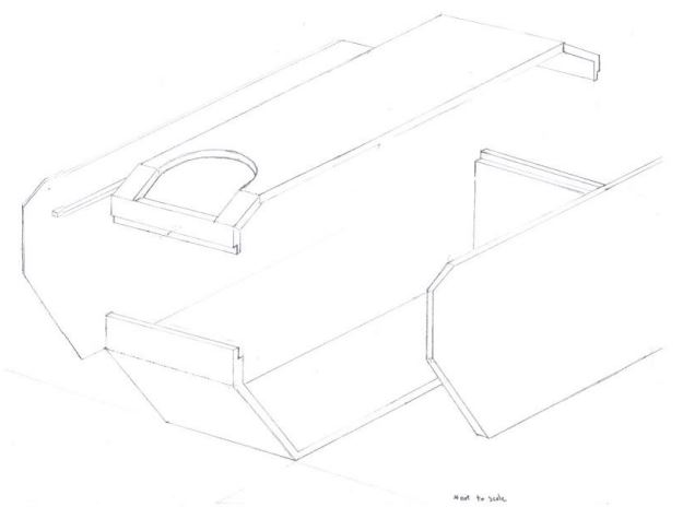
By: Jerry Lui (Manufacture)
Here you can see the base and the top portions that were designed on Solidworks. I removed a segments of the body to help reduce of the volume used () as determined through the Solidworks mass properties feature. The removed sections were also shaped in a triangular cross section to help increase the integrity. Also, the corners were filleted using Conic Rho of .1, which helps to maintain the triangular edge whereas a normal fillet would had changed the dimensions of the cutout to be too rounded. The mounting of the gears and wheel are still being designed.
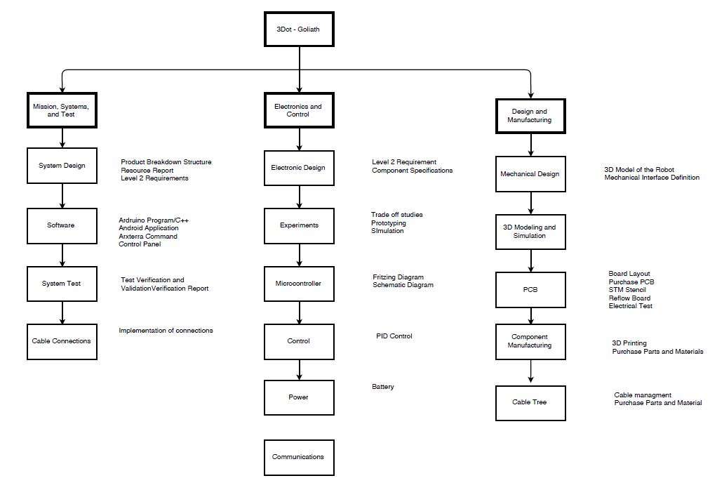
Product Breakdown Structure:
By: Tae Min Lee (Mission, Systems, and Testing Engineer)
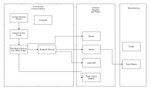
The product breakdown structure will show the components we will using for the Goliath. The Goliath will be broken into 5 major components mobility system, controller, 3Dot Micro Controller, vision, and a battery. The mobility system will provide movement to the Goliath by using two motors that will connect to the gears to turn the tracks. The controller will be used to control the Goliath by using a Bluetooth module and an arxterra application. Next, the 3DOt Micro controller will be used to control the motors, laser/LED, and the sensor. Lastly, the vision of the Goliath will be using a periscope that will be attached to the android camera phone. This will allow us to see in the robot’s perspective as we control it through the axterra application.
Preliminary System Block Diagram :
By: Tae Min Lee (Mission, Systems, and Testing Engineer)
Before we start the design of the Goliath we have to breakdown the product. This will allow us to understand what kind of components that are needed to create the Goliath. In addition, this helps us map out the connections for each component of the miniature rover.
One of the customer’s requirement was to use Arxterra program and an android phone. This will allow us to see the view in the robot’s perspective using the phone’s camera. We will then communicate with the 3Dot Board via Bluetooth module to control the rover remotely.
The new 3Dot board contains a motor shield with a turbo booster to drive the DC motors. However, there is a limitation to the 3Dot board of adding various output components (laser, sensors). We will create a custom PCB to be able to add connections for the laser and the sensors to the 3Dot board.
Lastly, the power supply will then be connected to the 3Dot board to power the motors, Bluetooth module, laser, and the sensors. These components will then be housed by the chassis, which will be designed and printed by the manufacturing engineer.
Electronics Control block diagram / Interface Matrix :
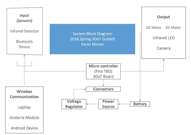
By:Kevin Moran (Electronics & Control engineer)
The block diagram shown above will show the electronic components we will be using on the Goliath. The blue tooth module will be able to send data to the Goliath to perform the basic operations in moving forward, backward, turning left, turning right, and shooting. We will be using two DC motors for our Goliath and a android phone to provide a via live video feed. All these components will be connected to the 3Dot Board and than powered by the battery.
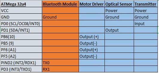
Interface Matrix:
The interface matrix is shown above to show the pins we will be using on the 3Dot board.
For the optical sensor it will be connected to power and ground. The output of this signal will be sent to pin PD1 and sent to either a buzzer to indicate a sound that we got hit or an LED.
For the transmitter it will also be connected to power and ground. The input of the transmitter will be sent to pin Pd0 and sent to a lazer/LED for the emitter.
We will be controlling two motors for our Goliath, which requires four pins with each motor connected to power and ground. First motor will be assigned to pB6 and PB5 for power and ground. Second motor will be assigned to PF6 and PF5 for power and ground.
Level 2 requirements – Subsystem
The rover will be controlled by two individual DC motors (3-5V)
An LED (or otherwise specified) will be used for a game of laser tag
Laser receiver (on PCB) must be 3 inches off the ground, in order for successful game
The 3DoT board will be used to control the rover
Unique Tasks:
Kevin Moran
Define the requirements for motor once the definite rover specifications are provided by project manager and systems engineer.
Using the power budget (provided by systems engineer) choose the correct batteries to power the rover for the specified amount of time (depending on laser game length).
Provide the required integration for systems engineer to control rover via Bluetooth
Design and implement the laser (LED or otherwise specified)
Design and implement the laser sensors on PCB by
Testing the circuit on PS SPICE
Designing the circuit diagram on EAGLE CAD to provide manufacturing engineers with the codes for them to implement the PCB
Place the laser sensor 3 inches off the ground to provide a fair game of laser tag
Solder the 3DoT board in order to implement the rover along with its components such as the motor, laser, camera, and PCB receiver
3DoT Board Information (Digital Pins TBD):
o Micro-footprint 35 x 69 mm (1.38 x 1.73 inches)
o FREE Android and Apple iOS application software
o Pre-installed Arduino program – fully customized for your robot
o Integrated 3.7v Li-ion battery charger
o 5.0v Turbo Boost for driving DC motors
o TB6612FNG Dual DC Motor Driver
o Battery Level Sensor Circuit
o Both Android and iOS Bluetooth Modules available (purchased separately)
o Powered from a single CR123A 650mA rechargeable Li-ion battery (not included) with PTC protection, or bring-your-own Li-Ion battery (SparkFun compatible connector provided).
o 8 MIPS (Millions of Instructions Per Second) 2-Stage Pipelined AVR RISC Architecture Input/output Soldering Ports
o I2C soldering port compatible with SparkFun 9DOF Sensor Stick
o Two 3.7v Micro and Ultra-Micro Servo ports
o 10 Digital I/O ports and 4 Analog ports (of the Digital I/O ports)
o All digital logic powered from Low Dropout (LDO) 3.3v regulator with power and ground output ports provided
Level 2 requirements – Subsystem
By: Rickeisha Brown and Jerry Lui (Manufacturing)
No Pan-tilt: must mimic German Goliath Rover
Verification : it was decided at during the meeting with the president.
Proper placement of the periscope (1”) to the android phone for visual accuracy.
Skeletonized body for weight reduction (< 2.87 lbs)
By: Jerry Lui (manufacturing )
The camera on the phone must be able to see through the 1’’ periscope.
Design PCB Gerber file using Eagle CAD, while working alongside Control division in verifying we meet size requirements (≤ 1”) for our design, making sure we minimize costs.
Solder IC components carefully on the PCB. If we get it right the first time, we do not need to order another PCB. Soldering IC components properly will be cost effective and time efficient.
Locate a cost-efficient 3D printing company (contact manufacturing division manager) to print out 3D components.
Jerry Lui :
Design and construct physical models or prototypes for dimensional references.
3D modeling of chassis using Solidworks, create a 3D model of the printable objects (chassis, LED housing).
Assemble internal components, such as PCB, 3DoT, motors, etc. to be tested for fit, finish, and function.
Test and verify that all moving objects on the rover are performing as expected.
Tasks Assignments:
Tae Min Lee – Systems
Will create the product breakdown structure of the product (3Dot Goliath).
Resource Report on the power and mass.
Validation of Level 2 Requirement.
Will learn C++ to program the Goliath using the Arudino IDE.
Will research on how to use the Arxterra control panel.
Verification and validation of level 1 and 2 requirements.
Provide a block diagram of the connections to each component.
Kevin – Electronics
Research on the type of sensors/lasers we will be using for the laser tag game.
Provide specifications of the sensors and lasers.
Perform trade off studies on the different type of sensors that can provide the maximum distance detection of the laser.
Perform a prototype of the laser detection system.
Provide a Fritzing diagram of the sensor and laser circuit.
Jerry Lui – Manufacture
Will create a 3D model of the 3Dot Goliath to provide an approximate dimensions for the robot.
Will perform a 3D model and simulation using CAD.
Keisha – Manufacture
Will layout where the components will be placed on the 3Dot Goliath.
Will be responsible for cable management when connecting the components to the 3Dot board.
Will purchase the PCB and perform the STM Stencil and re-flow of the board.
Preliminary Project Plan
Work Breakdown Structure(WBS):
By: Ayman Aljohani (Project Manager)
Action items, assigned tasks, would be based on WBS and PPS.
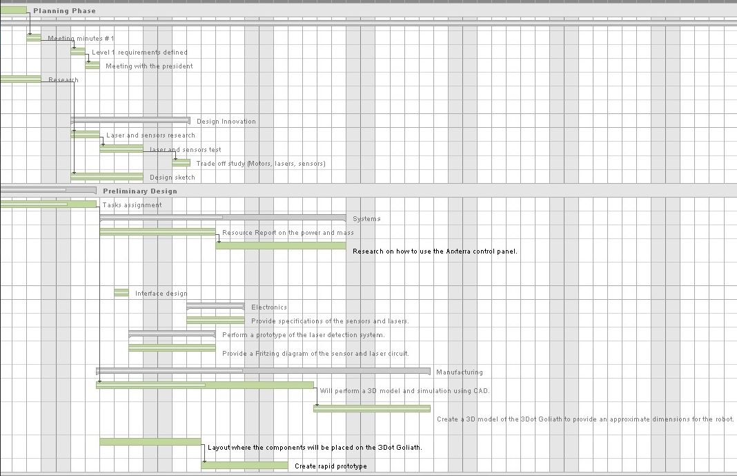
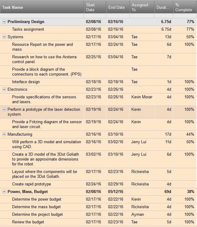
Project Schedule:
Top level schedule :
Highlighted in yellow is the top level schedule with assigned tasks and completion percentage
Water fall diagram:
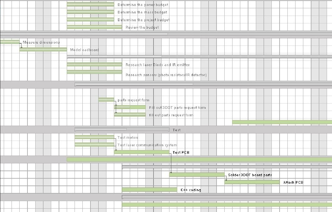
System/Subsystem Level Tasks:
Highlighted in orange is the subsystems schedule with assigned tasks and completion percentage.
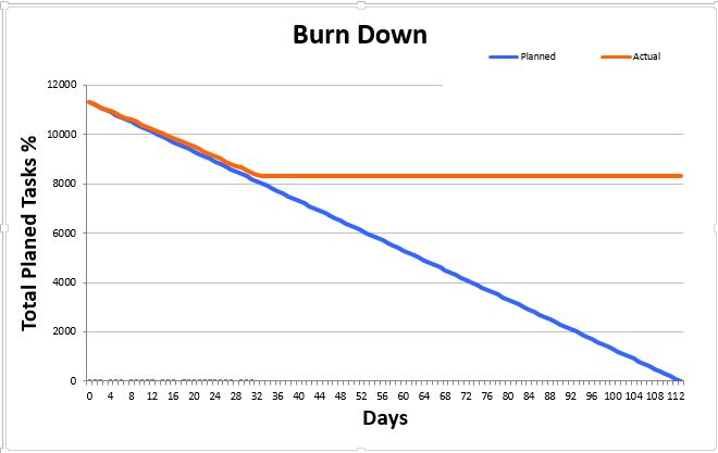
Burn Down and Project percent completion :
The Blue curve shows the planned tasks percent completion against the Orange curve which is the actual tasks percent completion.
System resource reports:
By: Tae Lee (System Engineer):
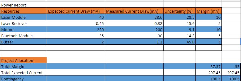
Power budget report:
The chart above shows the amount of power the Goliath will be using for the project. We calculated the draw current of each component and took the total amount. The total draw current will help us determine the type of battery to choose for our Goliath. There will be a total power margin of + or – of 37mA. To make sure we had enough current supplied to each component we added the contingency of about 100mA just in case a component draws extra current from the battery.
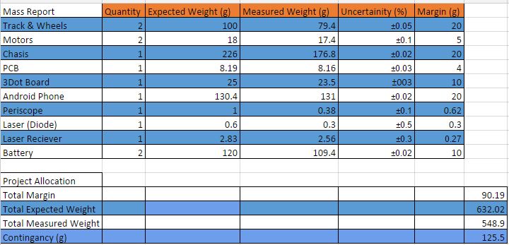
Mass report:
This is the mass report of the different components that will be used for the preliminary design of the Goliath. The allocation of the mass was determined based on the weight of each component. For the contingency, we set it to be roughly 1 pound to be safe (total 2.5 pounds) with an expected weight of around 1.5 pounds. The weight of the chassis was determined through Solidworks mass properties function with ABS as the base material (density of 1.06g/cm^3).
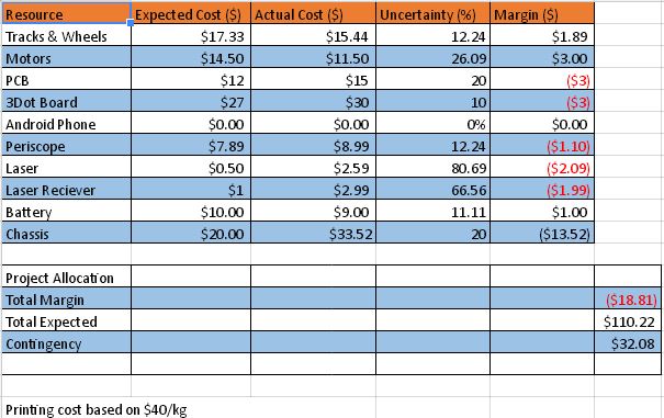
Cost estimate report:
The Cost Estimate Report shows the price breakdown for each component involved in building our Goliath Rover. Our customer is willing to pay up to $110.00 for the total cost of the design. It is our job as engineers to satisfy these financials limitations. Given that our Goliath design is “small” in size, including the 3Dot board, 3D printing & tracks and wheels, our overall cost will decrease. Please refer to our Cost Estimate Report for specific part costs.
The 3-Dot Goliath is a new project that will be working with a new board referred to as the 3- Dot board.
As a project manager, I will be responsible of my team’s final product, and making sure it meets the customer’s requirements (level 1 requirements) which are:
low-cost ( $ 90 total)
less 3D- printing time ( 6 hr maximum),small size Goliath look.
successfully compete in a laser-tag (optical transmission device)battle with 3-DOT Spider project.
sensor placed horizontally on the rover with zero degree along x-axis,located at a height of 3 inches above the ground.
When getting tagged three times, the rover should be disabled.
the rover should be piloted via a live camera view only.
looks of the RoSco has to be cool
From researching past projects, we have our preliminary budget as follows:
Tracks and wheels – $17.33
Motors – $11.50
Chassis- $5.07
ABS plastic- $ 18 (1 Kg)
PCB -$10
3DOT board-$30
Periscope- $6.89
Total cost: $ 98.79
I also conduct weekly meetings to followup on weekly actions.
Documentation is very important part of my assignment as PM.
2-minutes video for our project as a marketing tool, is also required from a project manager.
In order to meet those requirements, I have developed a work breakdown structure (WBS) where the the work is broken down into tasks assigned to each division with a deadline.
A prototype version of the project is schedule to be tested on week 5 of the semester.
A research on sensors in terms of (field of view, cost, safety, and interference from outside source) will be assigned to Systems engineer .Based on the research results, the type of sensor will be determined to be one of the following:
IR – LED – Laser – Ultrasonic
The research should focus on four main aspects:
cost
field of view
safety
interference from another external source i.e lights of the room, distance
The research will be joined efforts with our opponent robot team (3DOT Spider).
One important decision should be made as soon as possible is the type of communication devise used in laser-tag battle.
The 3D Dot Rosco is a new project that will require a little bit of research. We will be working with a new board referred to as the 3D Dot board.
Some of my responsibilities are performing
Verification and validation
Creating level 1 requirements
Creating the product breakdown structure.
Able to integrate everything together to create a product that meets the customer’s expectations.
Power Distribution
Testing of servos, motors, and sensors
From researching past projects I have noticed they used the Arduino board, Arduino motor shield, and a Bluetooth module that will be used to program a rover to do various tasks [7]. However, the new 3D dot board now incorporates all the hardware into a single board that will be used to control and perform various tasks on the rover. The 3D dot has dimensions 1.38 x 1.73 inches making it portable and convenient when printing 3D parts for the RoSco. Using the Arduino programming language (C++) we will then code and test the servo, motor, control panel, and the Bluetooth module[7].
Review of Literature:
Trade Off Studies of Batteries Review:
The blog post provided information on the research to determine which types of batteries will be suitable for the rover.
Notes for Requirements:
The research that was conducted on the type of batteries seemed unnecessary. This section should be replaced with a tradeoff study on the uses of different batteries. The group provided with informative information on the characteristics of the battery. However, it is more important to provide calculations to determine which battery will last longer for the rover. This requirement of comparing batteries does not contribute with moving the design forward. It would be better to narrow down a few batteries and documenting the amount of current that can be produced by the battery. Next step will to determine the milliampere-hour by adding up all the currents drained from each device to determine the total current. By doing this we can than calculate an approximate value of how long the rover will last by multiplying the total current with the desired operation time [1].
Level 2 and Level Requirements Review:
The rover team provided a good understanding of the level 2 requirements before building the product. They performed research on the terrain for obstacles and the distance that is needed to travel to fulfill the requirement. This included simple calculations to approximate the distance that was needed to travel. In addition, provided information and calculation of determining the required speed of .05 m/s. The next requirement was to determine a battery that will be used on the rover to last 20 minutes. Performing a simple calculation, they were able to determine the type of battery needed (890mAh) [2].
Note on Level 2 Requirements:
A recommendation to improving the blog is to combine the level 2 and level 3 requirements. An example of this is when they discussed the Power and the Power Storage. These sections are closely related and should be combined to make it clear to the reader of choosing the battery that will be used on the rover [2].
I agree with most of the level 2 requirements; however, the power storage will be modified because of the various components that will be used on the rover. The rover will be using a Bluetooth module, 3D Dot Board, laser, laser sensor, and two motors. This will require different type of battery that will power these components. In addition, the speed requirement will be changed by the customer needs.
Laser Communication Device:
We need to implement a sensor that is able to receive a certain wavelength from a laser. Once the laser hits the sensor it will send a signal to an LED or a buzzer to indicate we got hit by the enemy. The laser and the sensor will be connected to the 3D dot board and controlled by a wireless controller. This field will be further researched to be implemented on our rover [3].
New Requirements:
Battle with spider bot
Control methods (ex. Bluetooth, Axterra, or Both)
Sound indicator (ex. Detect when hit or firing)
Have fun
System Block Diagram:
The systems engineer provided a satisfying block diagram that shows the electrical interface of the rover. This includes the connections for the motor, illuminator, pan & tilt motor, and other components powered by the battery. We will be able to apply a similar block diagram with a few changes to help us create the new rover [4]. These changes include the laser, laser sensor, and the 3D Dot board.
Level 2 Requirements: (Based on requirement to make a “low budget” and “cool” rover)
Motor selection
In this year’s project we will be using the 3DoT board which comes with a motor shield and a voltage booster from 3.5V to 5V to control the motor speed. I will be testing the board to ensure it meets the requirements to power the rover. The motors should not exceed a combined force of 5V since that is the board’s limitations
Battery Life
In order to meet the level one requirements for a game of laser tag, the length of the game must be decided in order to ensure the batteries chosen for the task of powering the rover last until the end of the game. The selection of the batteries will depend on their mAh, their discharge rate, and size. Since our rover is the next generation and because of level 1 requirements, we must ensure it fits in the overall design of rover.
Laser Tag Game
Level 1 requires that a game of laser tag be played between the Rosco team and the Spider bot. The length of the match is still to be determined. Lasers will not be allowed in this laser tag game. An LED will be used in its place. In order to be able to hit a target, the LED must be focused on the objective.
Rover from previous generations:
In order to build a next generation rover, I read the documentation on previous projects, trying to learn from their successes but also their mistakes. To demonstrate the effectiveness of the 3DoT board, our rover must exceed previous expectations and results. Below are a few of the experiments done by previous groups.
Waterproofing Servo Experiment
In order to ensure the survival of the rover through its respective test course, the team needed to waterproof their servos to ensure full functionality in wet conditions, and completion of the required task. They enclosed the PCB in waterproof box. They had to spray the servos with plastic dip and submerged them under water for thirty seconds in order to prove they were safe to work in wet conditions. The only problem I see with this way of waterproofing is in the long run of the project. For our specific project we will not be able to waterproof this way, for we are not using servos. However, since we are using a prototype 3DoT board we need to be extra careful to protect from any outside interference, such as a single drop of water. All of our circuitry must be inside the rover and protected by our 3D printed rover.
Field of Vision Experiment
In order to fully simulate a soldier crawling through a barbed wire course, the designed their rover to avoid obstacles, to match the speed of a soldier, and visualize what a soldier sees in the crawling position. They tried to find the information on the internet but were not successful, so they decided to perform an experiment on field of vision. They needed the field of vision of a HTC Evo phone.
Power Budget:
The majority of the power was used by 6 different servos and 4 different motors. They needed to know the current the rover uses in order to figure out if their batteries were enough to complete the task. They were given batteries with 700mAH capacity, 7.2V batteries were used on previous semesters. By building their prototype, they were able to determine the exact current their rover would use when it was operational. They discovered that their batteries allowed them to run their rover for 40 minutes. For our project I need to determine how much power the laser will use, and for how long our game of laser tag will last. I need to ensure sufficient battery life for the motors and the laser circuitry. Since it is our first time using the 3DoT board, I will also need to run experiments and seeing how it functions and if it uses up much battery life to function since it’s such a compact design
New Ideas to meet level 1 requirements
Since the rover has been done by previous teams before using the Arduino plus a motor shield along with other components, in order to make our project a new generation we must improve on previous models. However, we must be realistic, we will not be reinventing the motor or the batteries used for the rover. Our focus will be to improve on previously known data. We will choose a similar motor and batteries but according to our 3DoT board, to ensure full cooperation amongst the subsystems. Below are some ideas to meet the level 1 requirements
Motor
We will research if 2 separate motors, or a single double-gearbox motor with individual control for the sides works best with the 3DoT board. The location of where the motor is placed will also play an important role, as it will allow for maximum torque and efficiency
Battery Life
Since the 3DoT board has a place for a lithium battery, we will research and see if a battery that can fit there can meet all of our requirements. Such as the voltage, the amperage needed during a certain amount of time, and the discharge and charging rates. Since our goal is to reduce costs by reducing the size, it would be ideal to just have 1 set of batteries. We must also figure out a way to charge the battery once it is already in place. I have thought of creating a USB adaptor and placing it on the side of the rover to recharge the batteries as needed. We must also be able to determine the charge of the battery at any given moment.
Laser Tag Game
In order to ensure a successful game of laser tag, I have suggested adding the “laser” to the pen tilt that will be holding the phone and the periscope. The point of any game is to try and have a good time (usually by winning). If we are able to have the laser point in the direction of the center of the periscope, we can potentially be able to target the other team by moving the pen tilt until their sensors are in our sights. This will meet the level 1 requirements by reducing the amount of single moving parts, and allowing our team a successful game of laser tag.
Crazy Idea
Since our point is to demonstrate the ability of the 3DoT board to power a rover by itself, I have suggested trying to take that a step further. If we were to be able to have two android devices control the rover simultaneously, our rover will be very successful. Person 1 would control the movements of the rover and speed, while person 2 will be control the pen tilt and trying to hit the laser sensors. Both persons would have access to the camera on their devices.
Manufacturing our rover incorporates the actual publishing and printing of the PCB board, soldering IC components and other necessary components to the IC board, along with designing 3D structure components. We will use Eagle Cad to draft our design of circuit boards, create a Gerber file and place an order with a PCB manufacturing company of the Manufacturing Division Manager’s choice. It is vital that we confirm with systems and controls a final PCB board design before moving forward with Eagle Cad and Gerber files prior to printing. It is our goal to utilize production time effectively for adequate testing time.
As stated, we are responsible for the 3D design of rover components on a computer software that allows us to do so. For the sake of time ease and access, our manufacturing team will use SolidWorks. SolidWorks will allow us to draft all parts required to manufacture our rover including: the chassis, gears, battery holder and shell.
The customer requests that our manufacturing team design a rover which mimics the German Rover Goliath. The German Rover Goliath has a distinct height and length ratio, such as 1:3. However, the most recent rover designs are replicas of Mars Rover and/or NASA’s Curiosity Rover, which have a height/length ratio of 3:1. Goliaths requirements:
Lower Cost (comparison to recent RoSco specs)
Minimizing use of 3D-printing
Smaller/Compact design
Smaller PCB
3D Printing Time: 6 hrs.
Chassis
Dimensions: 7.69×4.69×3.19
Miscellaneous bolts (prints provided by Division Manager: Kevin L.)
Goliath Replica
Tracks & wheel design
Chassis-body structure includes phone, PCB & 3 Dot wiring components
One level structure: no neck attached to pen tilt
Pen Tilt replaced Periscope
Range of view: Dependent on periscope specs-90 degree angle turns
Estimated total weight of Goliath Rover: 1.88-2.00 lbs
The manufacturing division will be responsible for the generation of an Eagle Cad design of the PCB Board, a 3D model of our Rover design using SolidWorks, & the calculation of material and supply needed to build the desired design.
Chassis material has to be light weight (at least under 1.63lbs)
Based on the previous Rosco project, the prime material to use for 3D printing would be ABS.
The overall weight must at least be less than the previous teams Rosco chassis weight of 1.63lbs.
The overall cost has to be low (<$80)
As per customer suggestions 3D printing should be used. This will cut down on costs.
ABS is priced, on average, $20 per kg or $9.07 per pound which can significantly reduce weight compared to PLA.
A game has to be implemented in conjunction with the 3Dot Spider-bot team
A led has been suggested to replace the original laser tag system as per customer request.
The Rover must be similar to the german Goliath ROV
A prefabricated, commercial track has been proposed to meet the customer objective of having a wheel-tracked system.
Suggestions
The body of the old Rosco was fairly bulky which accounted for the majority of the 3.25lbs. A more skeletonized body was proposed to help minimize the weight, speed up printing time, reduce costs, and to make it look aesthetically pleasing as per customer objectives.
The reduced weight of the body will also minimize the strain on the motor(s), and tracks thus increasing product longevity.
https://www.arxterra.com/wp-content/uploads/2016/02/blog-post-1-pic.jpg95144refaas0a/wp-content/uploads/2013/04/Arxterra-Logo-340x156.pngrefaas0a2016-02-10 06:30:462018-06-21 19:04:51Spring 2016 3-DoT Goliath Research and Intro
By Paul Oo (Project Manager)
Approved by Paul Oo (Project Manager)
Approved by Railly Mateo (Systems Engineer)
Executive Summary
Project Objectives and Mission Profile:
Fall 2015 MicroBiPed (BiRex) is inspired by the BiPed designed by Jonathan Dowdall of Project BiPed. The profile for this semester’s project is to use the BiPed & μBiPed designs to create a toy robot. The chosen design for a BiPed toy is a Tyrannosaurus Rex. To push the profile towards a feasibility demonstration requires a large emphasis on performance and budget. The objective of this project is to complete an obstacle course whilst controlled and communicating with the Arxterra™ Android application.
The detailed changes made to the Project Objective and Mission Profile can be found here.
Design:
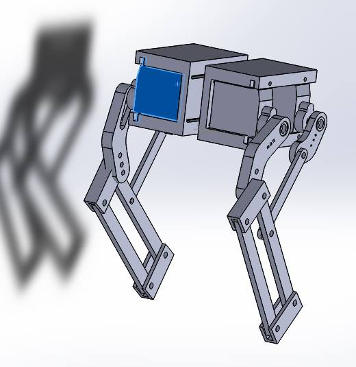
Figure 1 – Exploded Model
The image above shows the full 3D SOLIDWORKS structure. In this exploded view, the structure shows each individual component designed on SOLIDWORKS. Although there are additional components, (PCB, sensors, wires, and battery) this image shows the overall design of structure.
Details on the structure can be found further in this blog post under “Hardware Design.”
Project Features:
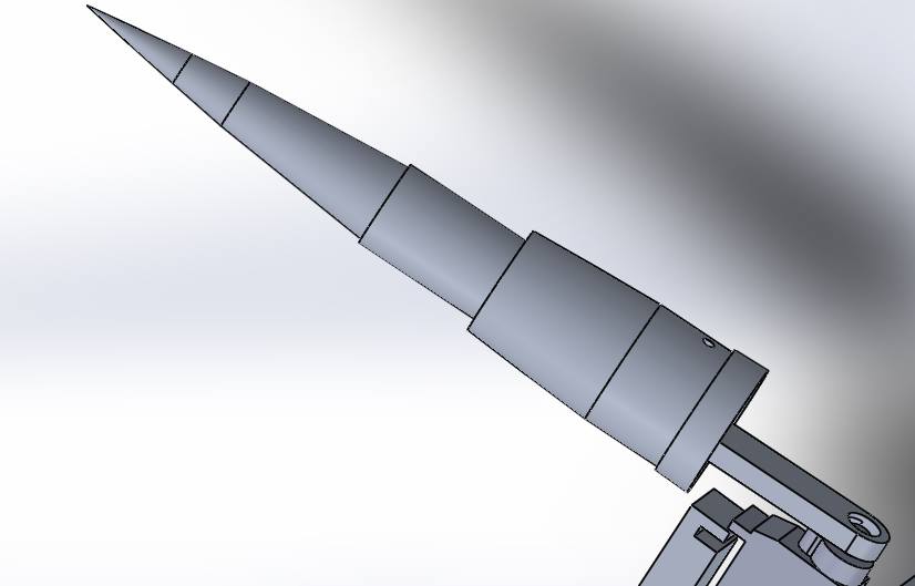
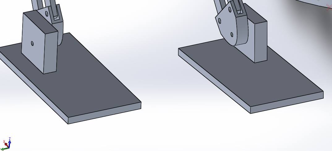
Figure 2 – BiLeg
Figure 3 – BiLegs
Figure 4 – BiHead
Figure 5 – BiTail
Figure 6 – BiFeet
The images above shows the creative solutions we implemented on this year’s µBiPed. During the production of the structure, our little BiRex was given the nickname of Bisexual T-Rex. Coincidentally, the name fit the design. Every one of these features have the capability to be flipped and still be functional.
Further analysis of Figure 6 (BiFeet) can be found in the Stress Analysis blog post.
System Design
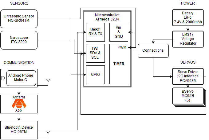
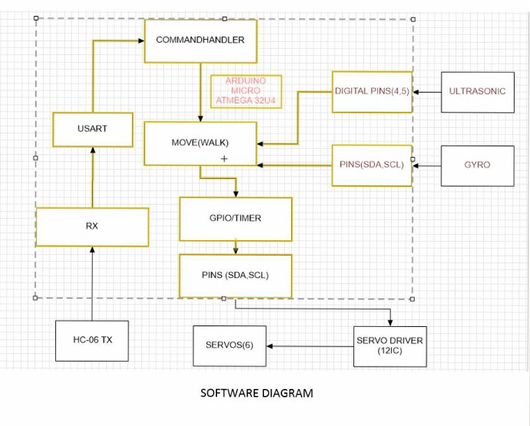
Fig. 7 – System Block Diagram
The block diagram above shows the updated block diagram for BiRex. This system diagram shows the high level information; mainly connectivity between subsystems through their peripherals. The blocks are positioned based on their subsystem information. As taught in EE 346, the microcontroller (Arduino Micro) acts as the computer to receive (inputs) and send out (outputs) information throughout the whole system.
The table above is a full list of experiments conducted after the PDR and up to the CDR. The titles that are bold are the next three topics (Battery, Prototypes, and Ankle) that give further information of each experiment.
Battery (Power Budget):
Item
Quantity
Max Consumption
Average Consumption
Total Average Consumption
Total Max Consumption
MG92B (servos)
6
0.7488170658
0.02
0.12
4.492902395
Arduino Micro (microcontoller)
1
0.85
0.37
0.37
0.85
Ultrasonic Sensor
1
0.015
0.015
0.015
0.015
Gyroscope
1
0.0065
0.0065
0.0065
0.0065
HC-06 (Bluetooth)
1
0.04
0.008
0.008
0.04
Total
0.5195
0.9115
Regular Amps Available:
2
Surge Amps Available:
10
Margin%:
284.985563
Margin%:
85.0343344
The above table presents the electronics subsystem that comprises of this year’s µBiPed project. The subsystem consists of both the main (Arduino Micro) and sub-components (servos, ultrasonic sensor, gyroscope, and Bluetooth communication). These components were then spec’d for quantity, max, average, total average, and total max current consumption. From this data, we used the specs from our chosen battery to find marginal current ratings.
The full description of the the system’s current draw can be found on the Power Budget blog post.
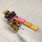
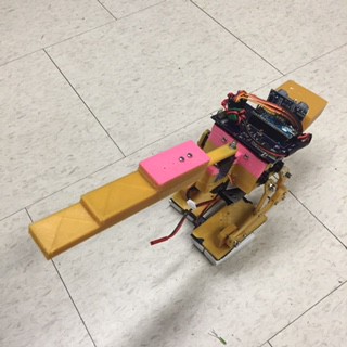
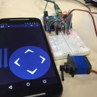
Prototypes:
This is the third video from the Prototypes blog post. This specific video shows how we used the prototype to get a better understanding for making our Bipedal robot walk. This model is considered the 2nd Generation (2.5) of prototyping BiRex. As you can see, it has difficulty walking. This lack of balance comes from the fact that our legs cannot support overall stability alone, thus verifying the need to add the head and tail.
Ankle:
Results:
Fig. 8 – Ankle: Stress Analysis
The von Mises test results. Solidworks allows you to determine which faces are stationary and which ones have forces acted on them. The ankle, which is the thick block, has all of the forces, and the red coloration indicates where the most vulnerable area is.
As a gauge, we considered the maximum force given by the robot as F = ma, which is the mass times the gravitational constant. In our case, 1.438 x 9.8 = 14.09N. The report indicated that the maximum force is above 65000N, which is way above our total forces.
Further details of the ankle design can be found on the Stress Analysis Blog Post.
Subsystem Design
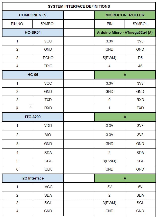
Interface Definitions:
Table 1
Table 1 above show the 1st portion of project’s updated system interface definitions. The left side of the table has information on our subsystem components, while the right side is simply the microcontroller (Arduino Micro). Each component is then defined by its pinout data (pin number and pin symbol), which is then used as information for the microcontroller’s pinout.
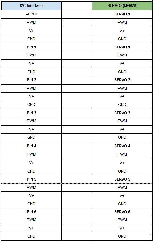
Table 2
Table 2 above show the 2nd portion of project’s updated system interface definitions. Unlike the first table, this section focuses only on our servo interface.
The system schematic blog post explains the steps needed to create an eagle file. The file used for BiRex is here: Eagle Schematic.
PCB:
Introduction:
The Final PCB layout is the responsibility of the Manufacturing engineer. To maximize the grade acquired for the assignment, a combination of through hole and SMD packages were utilized in the design.
Obstacles:
The problem presents itself when there are too many components on a board. Some components will have plenty of connections, sometimes to the point where there is no choice but to block other channels. Naturally, the solution to this would be to rotate the device. However, doing so can block even more channels. Another option is to create a double sided junctions. However, the double sided wires starts blocking other bottom sided channels utilized by other components. The only other option would be to go around it. Unfortunately, the free version of EAGLE has a limit of 2 in. x 2 ½ in; therefore, we do not have the liberty of space to maneuver around the conflicted part.
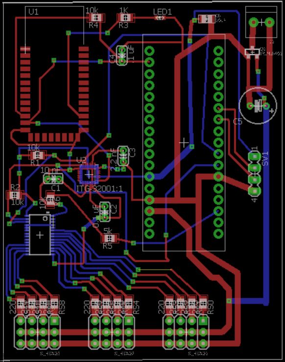
Final PCB Design. Note the part with the array of blue wires connected at the bottom left. That part is the servo driver, currently in the bottom of the board. Without it on the bottom, the order of the servo pins on the bottom would be convoluted.
The image above shows our finalized design for BiRex’s PCB. The red lines represent the copper tracing on top of the board, while the blue lines are underneath. An unpopular but effective method would be to have double sided SMD’s. By having an SMD on the bottom side, it is essentially mirrored by the axis that it is flipped on. This allows for some flexibility for routing.
Further details of interface matrix can be found on the PCB Blog Post. The full BRD file is provided here: MicroBiRex-Eagle.
Hardware Design:
3D Model:
The video above shows the simulation of the designed structure. The full STL file is provided here: Repaired. The full details can be found on the Center of Mass blog post.
Software Design:
Software System Block Diagram:
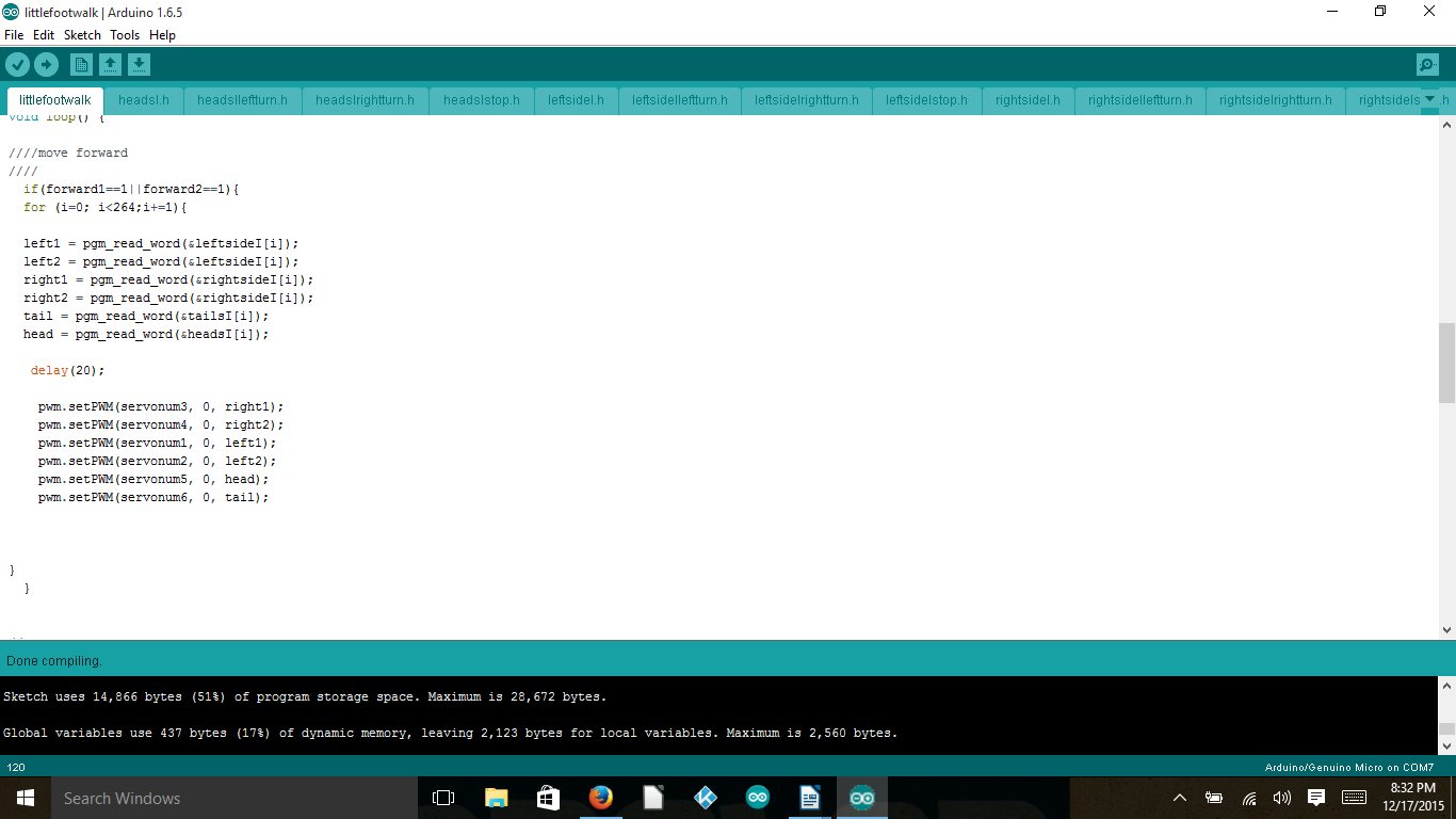
Walking Code (Introduction to IDE):
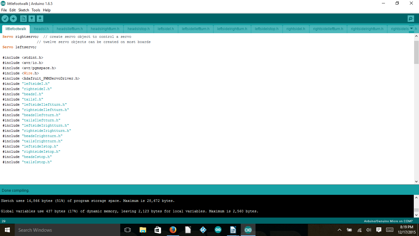
The walking code for the μBiped project was coded in the Arduino IDE using the basic syntax used in C, C++, and the like. The use of a servo-driver dictated the need of having the Adafruit servo-driver library (available here: https://github.com/adafruit/Adafruit-PWM-Servo-Driver-Library) added to the already existing Arduino libraries for use. The addition of this library allowed the use of more servos than would have normally been available using the Arduino alone.
PWM:
In order to control individual servos the Arduino would use PWM signals to the servo-driver with each PWM associated with a different angle. These different PWM values were then set in an array in order to allow smooth movement of the legs, head, and tail that the servos were made to control. In order to get smoother movement, longer arrays were required to show more individualized movements.
Fig. 1 – Include Files
The full details of the software design can be found on the Walking Code blog post. The full IDE file is here: IDE files.
Verification and Validation:
Test plans through verification and validation is needed to show the success of the project results. This document is then used by the course instructor. The document is essentially used as a checklist with results of the project tied to project and program requirements.
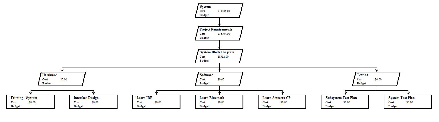
The Work Breakdown Structure (WBS) is used by those that deal with higher level program information The list of those involved include, but are not limited to: Project Manager, Systems Engineer, President, and Division Managers.
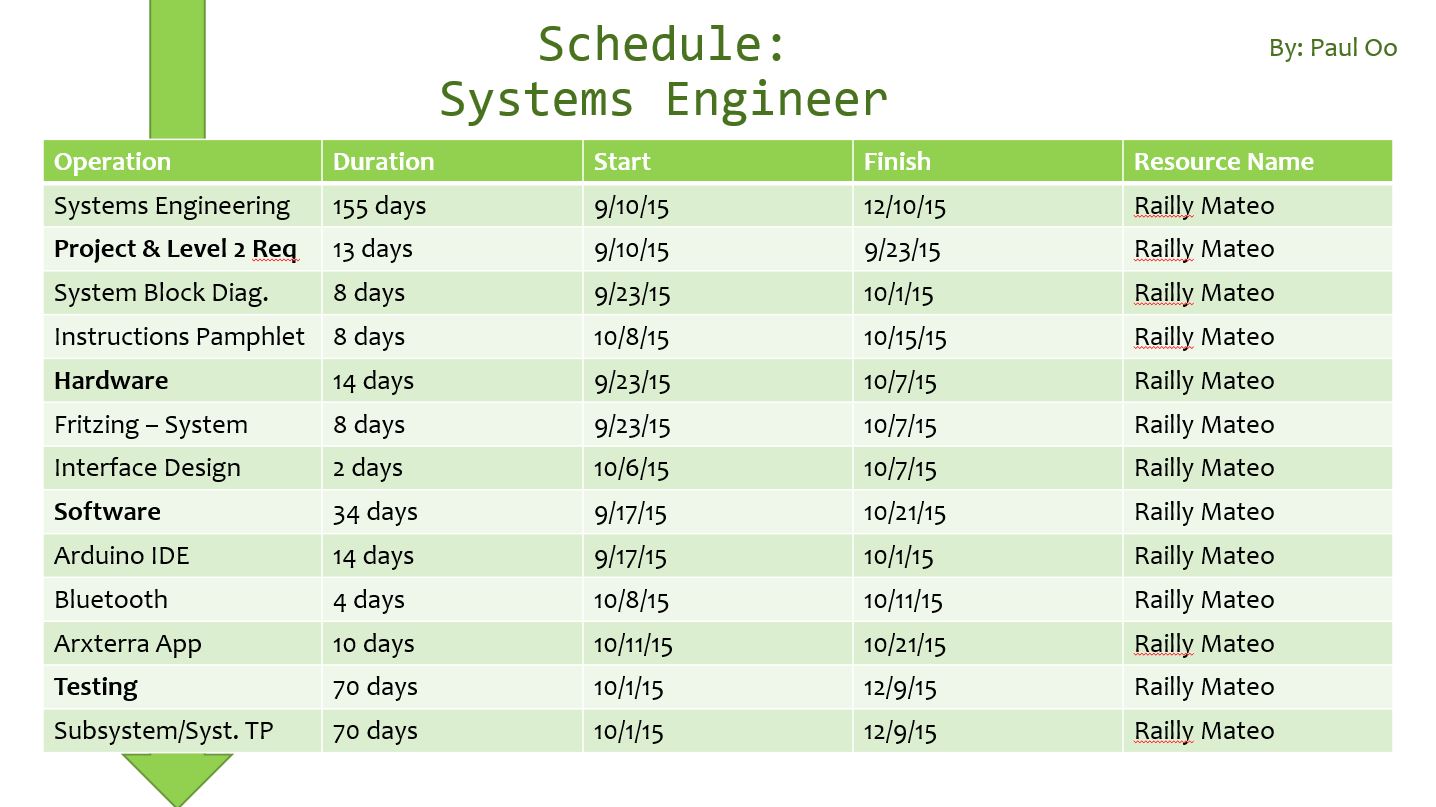
Table 1 – Project Manager
Operation
Duration
Start
Finish
Resource Name
Project μBiPed
162 days
8/31/15
12/10/15
Paul Oo
Project Management
155 days
9/10/15
12/10/15
Paul Oo
Mission Objective
21 days
9/10/15
10/1/15
Paul Oo
Program Req.
21 days
9/10/15
10/1/15
Paul Oo
Work Allocation
21 days
9/10/15
10/1/15
Paul Oo
PDD
8 days
9/23/15
10/1/15
Paul Oo
PDR
7 days
10/1/15
10/8/15
Paul Oo
CDD
21 days
10/8/15
10/29/15
Paul Oo
CDR
7 days
10/29/15
11/5/15
Paul Oo
Documentation
168 days
8/24/15
12/9/15
Paul Oo
Final Presentation
35 days
11/5/15
12/10/15
Paul Oo
Project Video
70 days
10/1/15
12/10/15
Paul Oo
The table above (Table 1) shows the schedule created for the Project Manager. This schedule has been made to fit Fall 2015’s 400 D timeline and milestones. Furthermore, the schedule has been broken down according to program tasks (Mission Objective, Work Allocation, & Documentation). To improve this schedule, along with other members’, project managers should view this document from the first day of being assigned to their position.
The schedule for Systems, Manufacturing, and Controls Engineers can be found on the WBS blog post.
Mass Budget:
Mass is important for every project. The mass can affect both the hardware and software design. While, the components used for movement are affected by the structure (load), the software must account for the physical resistances the structure produces.
Part
Quantity
Individual Mass (grams)
Total
(grams)
Margins
Servos
6
13.8
82.8
20%
#4 Hex Nuts and Bolts
18
20.7
372.6
10%
Frame
1
857.29
857.29
100%
Ultrasonic Sensor
1
8.5
8.5
10%
PCB (HC-06 & Arduino)
1
30.76
30.76
100%
Dynamite LiPo
1
86
86
10%
Grand Total (Grams)
1437.95
68%
The table above shows the data for mass of this year’s µBiPed project. The mass values obtained from data sheets are given a 10% margin of error. The frame’s mass is assumed to be an Aluminum build. Therefor, the mass may change drastically if a different material (polylactic acid) is more viable.
The full details of the mass budget can be found on the mass budget blog post.
Power Budget:
Power and Mass budgets are a bit more difficult to conclude early on. The reason comes from the changes that made to the structural and PCB designs as the semester progresses.
Item
Quantity
Max Consumption
Average Consumption
Total Average Consumption
Total Max Consumption
MG92B (servos)
6
0.7488170658
0.02
0.12
4.492902395
Arduino Micro (microcontoller)
1
0.85
0.37
0.37
0.85
Ultrasonic Sensor
1
0.015
0.015
0.015
0.015
Gyroscope
1
0.0065
0.0065
0.0065
0.0065
HC-06 (Bluetooth)
1
0.04
0.008
0.008
0.04
Total
0.5195
0.9115
Regular Amps Available:
2
Surge Amps Available:
10
Margin%:
284.985563
Margin%:
85.0343344
The above table presents the electronics subsystem that comprises of this year’s µBiPed project. The subsystem consists of both the main (Arduino Micro) and sub-components (*servos, ultrasonic sensor, gyroscope, and Bluetooth communication). These components were then spec’d for quantity, max, average, total average, and total max current consumption. From this data, we used the specs from our chosen battery to find marginal current ratings.
The full details to the battery used and power budget can be found on the battery update and power budget blog posts.
Progress:
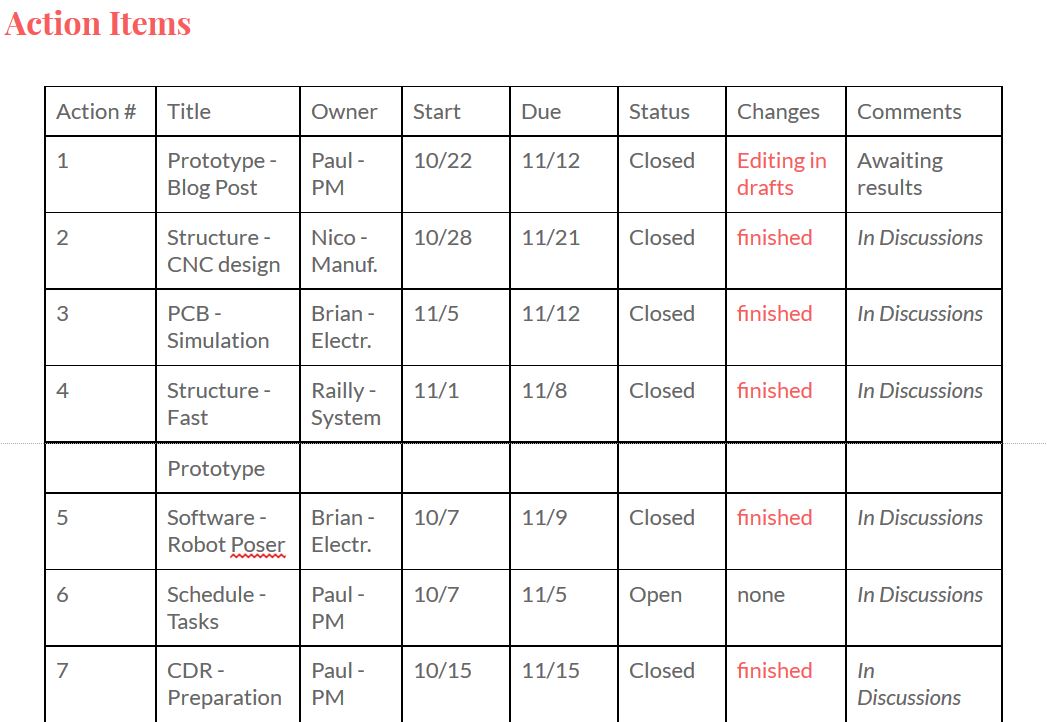
There are a multitude of ways to record the progress of your project. We used project libre as our initial source for layout the schedule. Unfortunately, the software’s user interface just wasn’t well designed. Regardless, the progress had to be documented. The most useful tool for progress actually came from using action items from the group meeting notes. This table allowed us to keep in touch of how close we are to small and large milestones.
Systems Engineer Schedule
Systems Engineer – Work Breakdown Structure
Meeting Notes – Action Items
Project Video:
The project video is a summary of BiRex and how we used the engineering method to produce our final result.
Conclusion for 400 D:
In conclusion, although it may seem infeasible, sticking to the program schedule will be the deciding factor to how successful your project will turn out. The project manager and system engineer should work hand in hand throughout the entire schedule to plan and prepare for any contingencies. The work they distribute is then placed on the subsystem engineers: manufacturing, electronics, controls, etc. Below is the recommendations I have personally made for future 400 D students.
Scheduling – Realistic 15 weeks
Weeks 1 – 4 : Students have two responsibilities:
Become familiarized with their project (Project Documentation)
The professor should debrief the intensity of the course and progress made per project (suggesting the difficulty in learning curve per project)
The students should be assigned for their positions coming into the course (given that they are provided with brief and/or full outline of WBS)
Become familiarized with their roles (Role Documentation)
The students should be assigned role research as homework assignment:
The students are then expected to present what they researched as an oral presentation (graded on content of information)
Work with division managers to implement certain software assignments (then create blog posts off of what they learned)
The purpose of these assignments are then to create a PDR
Notes: High learning curve for Project Manager and Systems Engineer
Weeks 5 – 8 : Students have one responsibility: Apply new-found knowledge to implement PDR towards CDR
The Project Manager and System should collaborate for scheduling
The schedules can be referenced from getting access to Drive or PDR
The subsystems should begin tailoring the researched 3D model, PCB, and IDE files to meet their PDR (rapid prototypes)
Weeks 9 – 15 : More prototyping and testing
Documentation – Implementation (Project vs. Role)
Project: Arxterra – Archive
Archive blog posts for individual community
To make it clear, add the requirement of titling each blog post with Semester, Year, Community, and event of post.
By Brian Walton (Controls Engineer)
Approved by Paul Oo (Project Manager)
Approved by Railly Mateo (Systems Engineer)
Introduction to Eagle:
Using EAGLE as a tool to build your schematic for all your subsystems offers multiple advantages:
1) Easy to use set-up aides with ease of schematic building
2) A large number of electronic companies support EAGLE and as such they provide libraries to add to your already existing EAGLE libraries to allow the use of their parts in the EAGLE software.
3) EAGLE comes with a built in PCB (Printed Circuit Board) software to easily go from the schematic to designing the PCB.
a) The available libraries allow using different size components as well as through-hole and surface-mounted components to add to the customization of the PCB to fit size and functionality requirements of the project at hand.
4) Building a schematic through EAGLE shows exactly what components are required for assembling the PCB allowing easy creation of a BoM (Bill of Materials) to simplify in the ordering of materials.
Our Eagle Schematic:
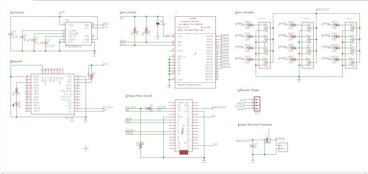
The full schematic can be downloaded from here: Eagle Schematic.
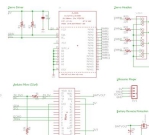
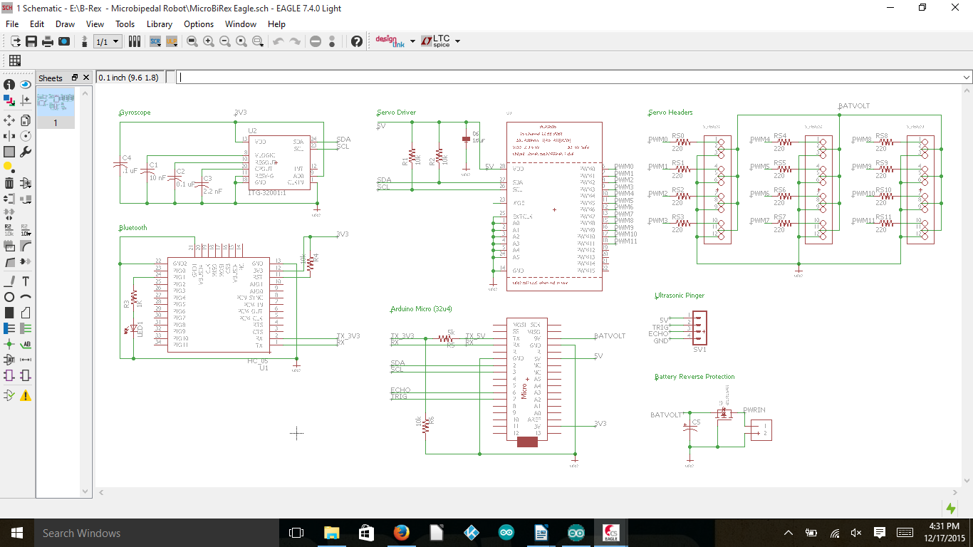
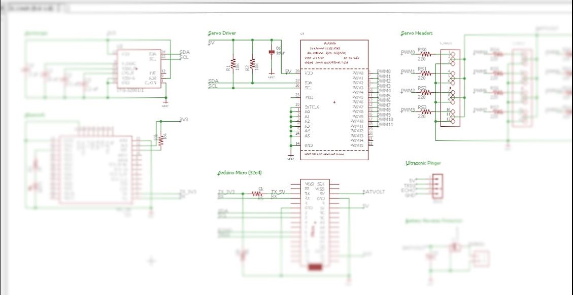
Fig. 1 – Complete Layout
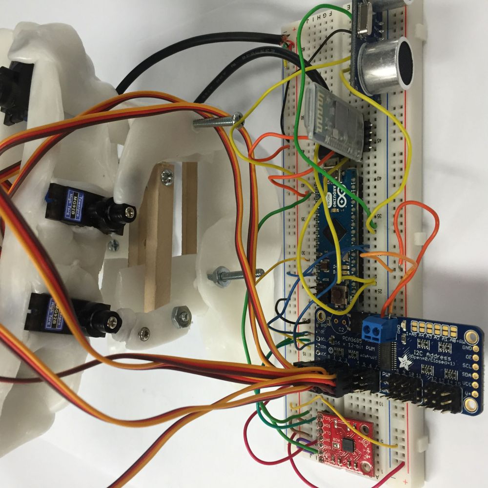
Project μBiped, also known as Project BiRex and Project Little Foot, required the use of a servo driver, Arduino Micro, Ultrasonic, Gyroscope, Bluetooth, and Battery Reverse Protection.
Fig. 2 – Gyroscope
Figure 2 focuses on the gyroscope from the overall schematic. It was decided to place the IC (integrated circuit) for the gyroscope directly to the PCB instead of using through-hole pins for the component itself. As a result extra capacitors had to be added to maintain the functionality of the gyroscoope.
Fig. 3 – Bluetooth
Figure 3 focuses on the Bluetooth from the overall schematic. The HC-06 was placed directly onto the PCB to allow wireless communication with the Arxterra application on a phone. The layout chosen for the schematic dictated the use of a HC-06 without a backboard.
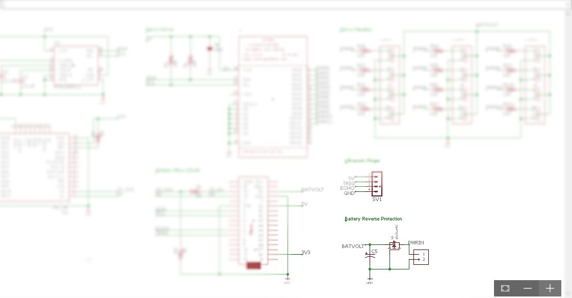
Fig. 4 – Servo Driver IC
Fig. 5 – Servo Driver components
Figure 4 focuses on the servo driver from the overall schematic. The servo driver IC was also laid directly onto the PCB, requiring extra resistors and a capacitor to maintain functionality. In conjunction with the servo driver, figure 5 shows the components needed to use the driver. It was required to have headers to be able to attach the servos to the PCB. Resistors were added onto the signal lines. The servo driver allowed the use of up to 16 servos which was quite a bit more than the 6 required for the project. The size requirement for the PCB allowed extra servo headers to be added to the design so the PCB allows for the use for up to 12 servos.
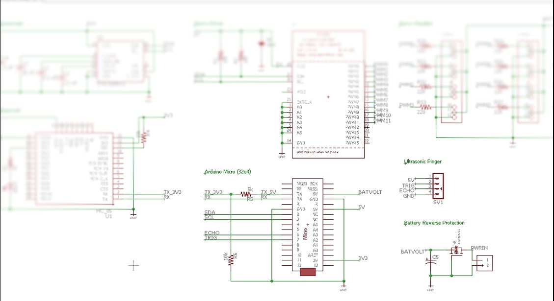
FIg. 6 – Arduino Micro and Ultrasonic Sensor
Figure 6 focuses on the Arduino Arduino and Ultrasonic Sensor from the overall schematic. The Arduino Micro and Ultrasonic were placed directly onto the PCB.
FIg. 7 – Battery
FIgure 7 focuses on the battery from the overall schematic. Battery Reverse Protection was added for added safety of components. The value of the capacitor used (1000 μF) was chosen based off of the number of servos used.
Notes:
Once the schematic is designed it is useful to label all connections and organize the schematic to aide in PCB design.
A copy of EAGLE can be downloaded here: http://www.cadsoftusa.com/download-eagle/
https://www.arxterra.com/wp-content/uploads/2015/12/eaglecover_compressed.jpg135149Plaulsible/wp-content/uploads/2013/04/Arxterra-Logo-340x156.pngPlaulsible2015-12-20 01:25:362018-03-08 22:21:00Fall 2015 MicroBiPed System Schematic
By Brian Walton (Controls Engineer)
Approved by Paul Oo (Project Manager)
Approved by Railly Mateo (Systems Engineer)
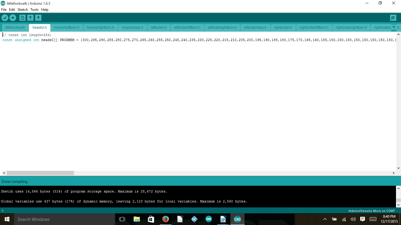
Introduction to IDE:
The walking code for the μBiped project was coded in the Arduino IDE using the basic syntax used in C, C++, and the like. The use of a servo-driver dictated the need of having the Adafruit servo-driver library (available here: https://github.com/adafruit/Adafruit-PWM-Servo-Driver-Library) added to the already existing Arduino libraries for use. The addition of this library allowed the use of more servos than would have normally been available using the Arduino alone.
PWM:
In order to control individual servos the Arduino would use PWM signals to the servo-driver with each PWM associated with a different angle. These different PWM values were then set in an array in order to allow smooth movement of the legs, head, and tail that the servos were made to control. In order to get smoother movement, longer arrays were required to show more individualized movements.
Fig. 1 – Include Files
Fig. 2 – .h Files
Once the arrays started getting passed 100 individual elements the Arduino Processor no longer had enough memory to handle this. Therefor look-up tables had to be incorporated. Using look-up tables allowed the change from the Arduino being unable to handle the individual arrays (which at the time there were only 4 arrays), to being able to handle 12 individual arrays (only taking up 17% of the dynamic memory and 51% of program storage space). In order to use program memory, figures 1 & 2 show how all of the arrays had to be saved as “.h” files and saved in the same file as the Arduino program.
Array Variables:
Fig. 3 – Variable Names
Fig. 4 – Variable Names (2)
Fig. 5 – Variable Names (3)
Fig. 6 – Variable Names (4)
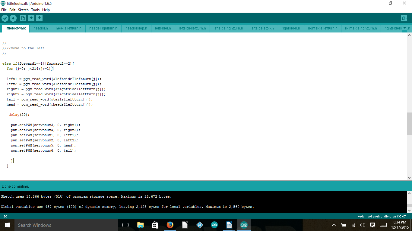
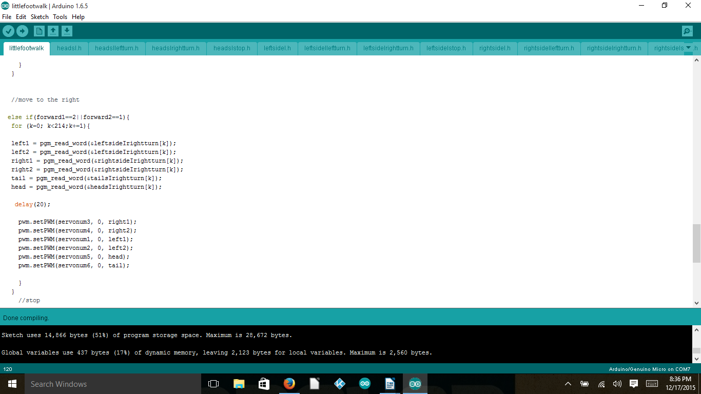
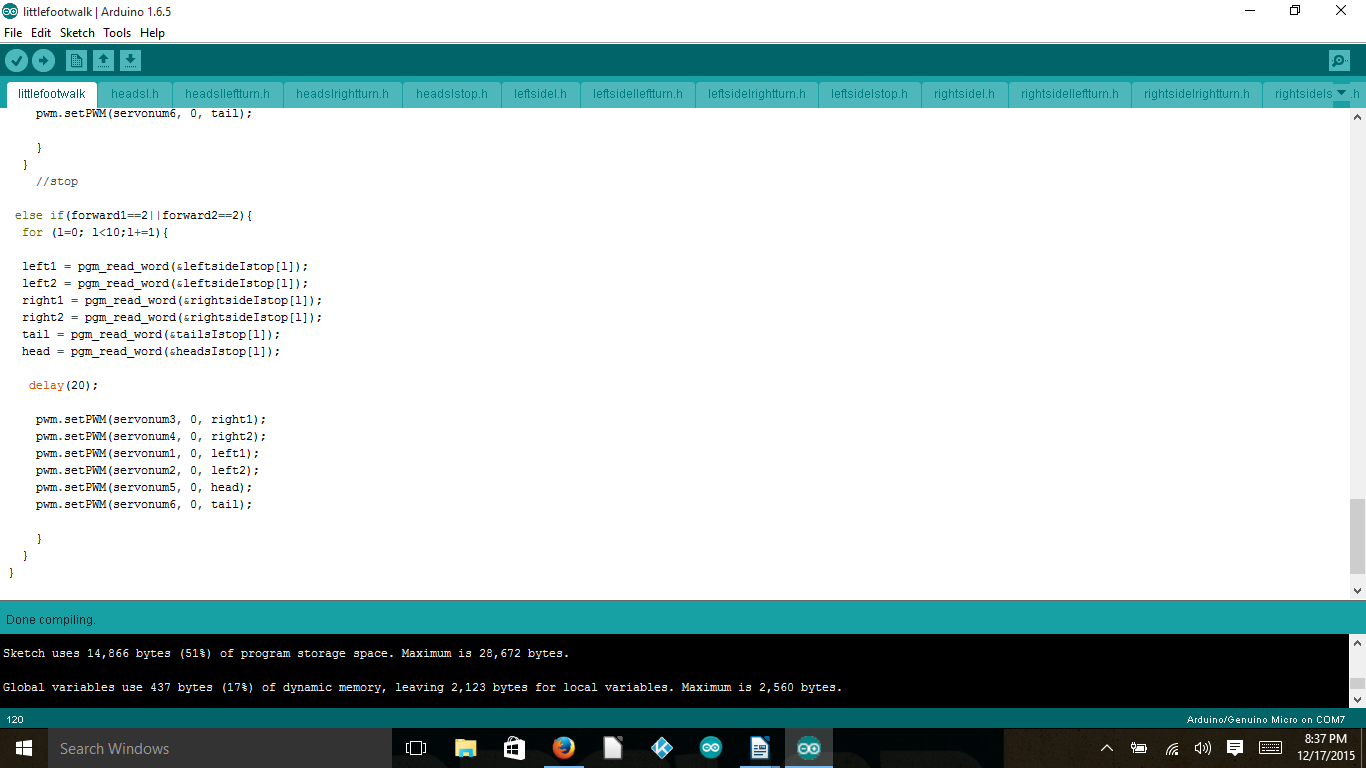
Figures 3, 4, & 5 shows the variables used in order to add ease to coding later. The variables i,j,k, and l were added in order to scroll through the individual arrays. The variables forward1 and forward2 were defined in order to communicate with the Arxtera application as the combination of these 2 variables would allow 4 different individualized movements desired by the project: forward, left, right, and standing still. The variables left1, left2, right1, right2, head, and tail are used to take the arrays and translate it to the 6 individual servos and allows the program to be more iterative.
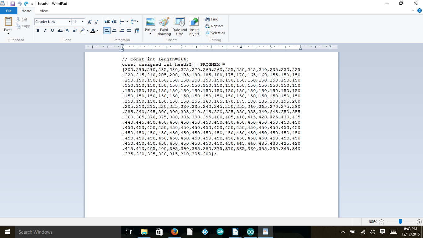
Long Array:
Fig. 7 – Array Example
In the Arduino IDE the included files show up as long arrays in different tabs along the top of the IDE. The creation of these “.h” files were made in WordPad and is shown in Figure 7 & 8.