Rover Team Servo Holder and Mirror

By Vinh Kim, 3D Modeling and Manufacturing

Introduction:
Using SolidWorks, the Rover project manager Maxwell had requested me to design him a servo and mirror holder.

figure 1 

Figure 1: Servo holder

 figure 2

Figure 2: Mirror

figure 3 

Figure 3: Servo holder and mirror with cell phone.

Height Requirement

By Maxwell Nguyen

Along the designated course shared by the Rover, Spiderbot, and Hexapod, the most notable obstacle was a sprinkler head with the height of four inches.  The orginal Arxterra RoSco is design to travel primarily through flat surfaces and is not equipped to move over obstacles at such height.  In order to clear this four-inch sprinkler, the rover team will be examining a design solution that will allow the new rover to achieve the height requirement.

The rover team has agreed that extending the height of the rover is the most simple and efficient design solution in order to fulfill the height requirement.  By taking the original chassis (or body) of the rover and extending both sides we will be able to give the rover a height clearance of 4 inches.

body

In order to extend the sides, several methods will be weighed against each other.  One approach will be to have the manufacturing division remodel the chassis of the rover to fit our needs.  However, due to time constraints and inefficiency from remodeling the chassis we will opt for a difference solution.

The most efficient solution the rover team decided upon is to mount two wooden height extensions, one to each side of the rover.  This will eliminate the need for plastic remodeling and simplify our design solution.  Similar holes drilled into the bottom of the wooden extensions will allow us to mount the motors, wheels, and track at the bottom of the extensions.  This will thus give the rover a significant height increase.

Track Research

By Maxwell Nguyen, Project Manager

 The rover team is researching new ideas for treads/tracks for the rover.  The current tread belt is one continuous belt that takes hours to print.  In addition, one small mistake could potential ruin the entire track and make it completely useless.  In order to fix this problem, we will be looking into a new design that allows the belt to be split up into separate pieces.

Upon further research, we concluded that it was best to create our tread belt to resemble tank treads.  Tank treads are effective and can be produced as individual pieces before linking them into one continuous belt.  This will allow for faster track production and reduce the margin for error on the manufacturing end.

When searching for tank track models on Thingiverse (an open source community for 3D models and printing), we narrowed down three different types of tracks.  They can be viewed in the links below:

http://www.thingiverse.com/thing:163489

http://www.thingiverse.com/thing:163486

http://www.thingiverse.com/thing:199713

We will be working closely with the manufacturing division to develop a set a tracks and a new wheel to fit that will meet our rover’s needs.

Wheel Consideration

by Robert Licari and Anthony Vo

We can take the wheels into consideration for the purpose of finding our desired velocity based upon our calculations.

If our Wheel Diameter (D) is 45 mm, then we can conclude the Radius (R) is as follows:
R= D/2 = 0.0225 m

Now we require a velocity equation that relates velocity to our wheel. For this task, we can employ a basic velocity equation with relation to angular velocity:

V = (R*w)/sin(theta)

Where “w” is angular velocity and our conversion from RPM to rad/s is as follows:

1 RPM = (2*pi )/60 rad/s

The spec that we have four our free-run RPM is 85 RPM @ 6V, which we shall use to find our normal velocity. In tandem with this, our application of the wheel requires that the angle “theta” be 90 degrees, or perpendicular, to our rotational axis, which effectively gives us:

V = 0.0225m * [ 85 RPM * (2*pi/60 rad/s) ]
 =~ 0.2003 m/s

 This equation can be applied to varying Diameter, but, for our purposes, we will use the 45 mm wheel.

 Level 1 Requirement:
— Speed according to the wheel diameter —

 The velocity requirement is defined base on matching the velocity of the standard ROSCO.  To calculate the velocity of the ROSCO, the circumference of the wheels and RPM of the motors is taken into account.  Given the wheel diameter, the circumference of the wheel can be calculated.  After scaling the measurements to meters and seconds, the rover is expected to have a velocity of at least 0.200277 m/s or ~0.2003 m/s.

Power Consumption Theory

by Robert Licari and Anthony Vo

Before we begin it is imperative to note that the power consumption equations calculated are heavily related to the amount of torque required to move the motors from rest to forward motion. In accordance with that idea, the following theory is calculated considering the worst power conservation possible. By that, we mean that there is probably no way that the Rover will draw this much power, but the fact of the matter remains that the equations are scenarios that can, and probably will happen. Our theory at this point considers that these scenarios are happening constantly.

 Having said that, we can do some simple addition in order to compare our power consumption:

 Power_DCMotor + Power_Servos = Motor Power Consumption

 5 W + 3 W = 8 W

 Now if we do a simple calculation involving the current, we can find the total current drop that the Rover will consume:

 8 W = 8.4 V * I_total

 I_total = 0.9524 A

 If our battery output is 800 mAh, then we can easily state:

 Operational Time = 0.8 Ah / 0.9524 A = 0.84 h

 0.84 h ~ 50 mins

Given our simple calculations and considering only the power consumption of the motors itself operating constantly at their rated voltages, we should be able to run the motor for approximately 50 mins.

Bear in mind that this is an ideal situation and is not considering physical constraints and is assuming constant heavily-powered motion from our motors. The reason the calculations were done this way is to illustrate a time that was within our overall assumptions as well as a starting point for the next phase of calculations being the physical constraints of our payload (the rover itself) as well as additional power concerns involving the microcontroller.

Subsystem Requirements: Power Budget

by Robert Licari and Anthony Vo

Power supply of the Rover:
Rover must provide sufficient power to clear the course of 50m.

To ensure that the rover is able to complete its mission in a timely fashion, the rover’s load cannot exceed 6.72 Wh. For this to be true, we must consider how much power and current draw will go into each of our major components powered by this battery pack. In accordance with this math, we should be able to run approximately 13 W of power during the duration of 30 mins. Keeping this in mind, we will continue with the analysis of our motors.

DC Motor:

120:1 Plastic Gearmotor 90-Degree Output


Typical operating voltage: 6 V
Gear ratio: 120:1
Free-run speed @ 6V: 85 rpm
Free-run current @ 6V: 70 mA
Stall current @ 6V: 800 mA
Stall torque @ 6V: 75 oz·in

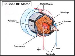
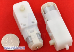
The single most important consideration that we have is with our DC Motors. We will be running two motors which will alter the above specifications as follows:

 Stall current @ 6V =>            1.6 A
Stall Torque @ 6V =>            1.05924 N-m   (converted from 150 oz*in)

Given this information, we will be able to determine that ~1 N-m of torque is where our DC motor will stall a will effectively put us dead in the water. So long as our torque remains underneath this value we can safely say that our current draw will be under 1.6 A and that our motors will not stall.

 For this purpose, we will be working backwards. Our considerations will work from an outlandish power involving our Stall values, and we will be able to take steps backward in order to figure out where we want to be in terms of power usage and current draw.

 Therefore, we will, once again, use our power equation utilizing our stall values and our rated voltage:

P_stall = V * I_stall
P_ stall = 6V * 1.6 A

= 9.6 W

This value is our stall power for both of our motors at Stall. Now, we do not wish for our motors to stall because that would be detrimental to our fundamental mission objective of forward motion. Therefore, we will simply scale backwards from our stall power and find a current draw that will fit with the specifications of our battery pack.

 Here are some basic equations demonstrating this:

Let I = P / V
If P = 9 W then
9 W / 6 V = 1.5 A

If P = 5 W then
5 W / 6 V = 0.83 A

 If P = 3 W then
3 W / 6 V = 0.5 A

These current values will be considered when we bring our Rover from rest to forward motion, and are integral to the mission objective. From a purely theoretical standing, the motor will never draw this much power at free-run, but we must also consider that the amount of time that our rover is at free-run speed will be minimal given the nature of the course we must navigate. Taking these into consideration, it is best to err on the side of the worst case scenario in order to avoid the necessity for a new battery pack or motor.

To meet our loose requirement for under 13 W of power consumption, if we consider our motors to draw about 5 W collectively, we are well under the power consumption thus far.

Also, do keep in mind that we are using the specification of 6 V, which can be subject to change as a work-around for our power budget.

Servo Motor:

 Towerpro MG996R 10kg servo
Weight                                    55g
Dimension                              40.7*19.7*42.9mm
Stall torque                            10kg/cm = 0.01 kg/m
Operating speed                    0.20sec/60degree(4.8v)
Operating voltage                  4.8-7.2V
Temperature range               0_ 55
Servo Plug:                             JR (Fits JR and Futaba)

Just like for the DC Motor, we will consider a purely electrical requirement. We will use the same approach that we have used previously but utilize different formulae in order to account for our different specifications.

Our first goal was to find an equation that could accurately and easily find a reasonable power consumption. Therefore, we will be using this equation:

P = ( N * T ) / C_1

For the use of this equation, we will use the fact that N is the number of revolutions per minute (RPM) and that C_1 is a Torque conversion constant related to the desired units of power that follows the below table

We must also consider that our operating speed is in improper units as well. So we will use the conversion provided by our conversion calculator (see Sources), which will give us the following:

0.2s / 60 degrees = 1/300 s/degree

 => ~50 RPM @ 4.8 V

Now that we have our operating speed in RPM, we can begin using our new power equation in order to discover what our stall power is and work backwards just as we did with the DC motor.

If P = ( N * T ) / C_1

Our stall power will be the following:
P_stall = ( N * T_stall ) / C_1
= ( 50 RPM * 10 kg/cm ) / 97.3

= 5.1387 W

This tells us that our maximum power before stall is ~ 5 W at our operation voltage of 4.8V. Now if we work backwards just as we’ve done before:

If P = 5 W then
5 W / 4.8 V = 1.0417 A

If P = 3 W then
3 W / 4.8 V = 0.6250 A

For our application here, we have a tremendous amount of flexibility with the servos. Unlike the DC Motor, the servos will not be running constantly in order to fuel our objective, but we must also consider that there is a finite amount of power that we have at our disposal. Therefore, if we propose that our servos run at approximately 3 W collectively then we can use that in our calculation of our battery life.

Motor Trade-off Study

By Anthony Vo

In order to decide which motor will meet our level 1 and subsystem requirements, it is important to conduct a trade-off study of several motors.  The goal of the trade-off study is to compare and contrast the RPM, current draw, torque, and cost of each motor.  From the trade-off study, we will be able to determine which motor will best fit out design specifications.


Type of Motor

plastic gearmotor

GM8

GM9

GM10

GM17

Cost

$5.75

$5.75

$5.75

$9.26

$5.75

           
Voltage (vdc)

6

5

5

5

6

Current (mA) free-run

70

57.6

73.2

24.6

29

Power=IV (mW) electrical

420

288

366

123

174

RPM (speed)

85

70

66

370

32.4

Torque (oz-in)

75

43

43

3.6

69

Torque (kg-cm)  

3.096

3.096

0.26

4.97

Torque (N-m)

0.529

0.303

0.303

0.025

0.487

Reduction

120:1

143:1

143:1

81:1

228:1

Weight (grams)

32

32


5

35

Weight (oz)  

1.13


0.176

1.23

Above is a chart of 5 different motors with a hyper link to each one.  The description and specification for each motor is arranged into a chart for easy comparison.  From the data above, we have narrowed down our motor to 2 choices: the GM8 and the plastic gearmotor.

GM8:
The pros for choosing the GM8 over the plastic gear motor include lower current draw at free-run and lower power consumption.  The lower power consumption allows us to meet our power requirement defined in the subsystem requirements.  However, this motor will not provide the RPM required to achieve our speed requirement at the rated 5 volts.

Plastic Gear Motor:
The pros for choosing the plastic gear motor over the GM8 include higher RPM and higher torque rating.  The higher RPM ensures that our level 1 speed requirement is met.  This motor also provides more torque which will allow the rover to move over more difficult terrain without stalling.

Conclusion:
After comparing the two motors, we are leaning towards the plastic gear motor.  Although the motor is less power efficient, it will still meet the subsystem power requirements.  The plastic gear motor will provide the RPM and torque we need to drive the rover at our speed requirement.

Mirror Study

By Maxwell Nguyen

In order to eliminate the need for larger servos, the rover team will be implementing mirrors to provide vision for the rover.  As compared to lifting a phone, the torque and power require to lift a mirror is substantially less.

Objective:
The objective of this study is to examine whether a mirror used for vision control will provide a clear and undistorted image.

 A study must be conducted in order to verify if mirrors can be used for the pan and tilt vision.  We will use a basic, homemade apparatus to test the camera vision through the mirror.  The apparatus can be seen below and consists of a mirror taped to a small booklet to provide stability and a tilt function.

2 

Mirror apparatus

Equipment and materials:

   -Phone with camera
   -Mirror
   -Tape
   -Small booklet

Procedure:
The setup will have the phone placed on a flat surface with the camera facing up towards the ceiling.  The phone will remain stationary throughout the entire test.  The mirror apparatus will be placed directly over the camera.  Using the flap of  the booklet, a tilt function can be simulated.  By turning the booklet/mirror left and right, we can simulate vision control to the left and to the right. 

 3

Test setup

 4

 Test setup(different angle)

Results:

The following short clip provides results to the mirror study.

Conclusion:
Mirrors do in fact provide a clear image for the camera.  Tilting and panning of the mirrors shows no distortion.  From this study, the team will move into designs to implement the mirror on the rover.

Rover Level 1 Requirements

By Maxwell Nguyen

Level 1 Requirements:

Our top mission requirements are derived from the specifications of the standard Arxterra Rosco.  The requirements will include speed, power consumption, cost, and time.

Speed:
Our rover is expected to move at a speed of 0.200277 m/s.  This is calculated using the standard wheel diameter of 45mm and RPM of the motor. 

Wheel diameter = 45 mm

 wheel

3D model of wheel


Motor Specs:
120:1 Plastic Gearmotor 90-Degree Output

 motorspic

Free-run speed @ 6V: 85 rpm

Velocity calculation:
Radius = d/2
R = 0.045/2
R = 0.0225 mm
Circumference = 2*pi*r
C = 2*pi*0.0225
C = 0.141372 m

Velocity = RPM*C

V = (85 rot * 0.141372 m)/60 sec
V = 0.200277 m/s

Cost:
Must have a lower cost compared to the standard RoSco of $284.13.  The BOM for the standard RoSco can be found in the two links below.  The first one lists the parts and links to find the parts while the second link provides a sum of all the costs of each part.

Parts list and where to purchase them.

Rover Projected Cost List

Time:
The rover must be completed by May 12.  This takes into account CSULB’s final exam schedule and deadline for the project.

Spring 2014 Rover Introduction

By Maxwell Nguyen

This new semester brings along a brand new team with inventive and innovative minds. The rover team will be aiming to create a brand new and improved design for the RoSco Rover.

The Rover Team includes:
Maxwell Nguyen – Project Manager
Robert Licari – Communications
Anthony Vo – Sensors, Actuator, Powertrain
Suhyun Kim – Image Processing, Computer Systems

Mission Objective:
Construct a rover that will be able to navigate through a natural set course shared by the Spiderbot and Hexapod.  The rover must be able to navigate around sprinkler and branches on the course.  The route was determined by the Spiderbot team and can be viewed below.

map
course top view

mapIllo

Course map view

The course is located in the East Wind of campus and is about 42 meters long.