Wireless Remote Communication Using XBee Radios

By Jake Rice

The Remote Control

In order to meet the requirement of wireless communication between the UFO and the user, the UFO was equipped with an XBee radio. A remote control with 2 joysticks to enable the user to control the UFO was also equipped with an XBee radio. The joysticks control 2 10k-ohm potentiometers, with one for the vertical axis and one for the horizontal axis. Since the ADC has a maximum input voltage of 1.2 volts and the XBee reference voltage is 3.3 volts, a 22k-ohm resistor was placed in series with each potentiometer to limit the maximum input voltage to 1 volt.

XCTU Remote Configuration copy

Configuring the XBees

The two XBee radios were then configured to communicate with each other using XCTU. In order to communicate, two XBees must each have their destination address match the serial number of the other XBee. The UFO XBee must be set as a coordinator and the remote control XBEE must be set as an end device. To allow the XBee on the UFO to communicate serially with the Arduino, both XBees must be set to API (Application Program Interface) mode. IO pins 0-3 on the remote control XBee must be set to ADC mode to be used as inputs for the joysticks.

 XBee Data

While the two XBEEs are communicating in API mode, the remote XBee sends the UFO XBee packets of data called frames. The length of the frame depends on the amount of data being sent, and with 4 inputs the remote XBee sends frames of 20 bytes. The first byte of the frame is always the start delimiter 0x7E, which is used to determine where each frame begins. Bytes 12-19 contain the data from the ADC inputs on the remote.

XCTU Frames Being Received copy

Interpreting the XBee Data

In order to isolate the potentiometer values from the incoming frame, the Arduino program waits until an entire frame’s worth of data (20 bytes) has been received. It then checks to make sure the first byte of the frame is the start delimiter (0x7E). Then, the program skips to byte 12, where the input data begins. Each potentiometer reading is represented by 2 bytes, high followed by low. The program multiplies the high byte of each reading by 256 and then adds the low byte to store each reading in a single variable.

Testing the Remote Control

As a test of the remote’s ability to control the speed of the UFO’s fans, the Arduino program was configured to read the vertical position of the bottom joystick. The range of possible values from that of the joystick’s neutral position to that of its highest position were mapped to the range of fan speeds from 0% to 100% of maximum thrust. The UFO was secured in place and both the UFO and the remote control were turned on. As the user moved the joystick up, the speed of the fans increased accordingly.

Implementing the Air Ducts

By Juan Montano

Hello all, this study was made to determine if the air duct would be able to resolve our issue with having fans rotating in one direction.

First of all, we would like to see how our fan performs as of now. Below, you would see the fan blades that we currently have:

1

Now, we will use SolidWorks to determine the airflow:

2 

3

As seen above, we have airflow going down, through the fan, and out as a vortex. The air flows like an upside down whirlwind, which would turn into a problem if there was another fan spinning the same direction. Let’s see what happens with two fans flowing the same direction:

4

We see some turbulence in between the two fans.

Here is another example:

5

Here we can see more clearly that there is airflow going upward instead of just straight down, which will be a problem.

Next we see how the airflow goes using the air duct and the fan assembly:

6 

7

Our fan model and our air duct model. Put together we have:

8

Here is the airflow:

9

The airflow seems to be more stabilized now, however, we want to have some control over yaw, and therefore we reposition the air ducts like so:

 10


11

We see that it will behave ok. Still see some concerns in between the two fans however, that would be manipulated to try to get yaw control. We redo the simulation using our SolidWorks model:

12 13

Here we see the UFO with some air flow. Here we note that the air curving back to the top of the bottom was due to the limited boundaries and high rotational speed of the fan. SolidWorks simulated these airflows inside a 3D box to decrease the amount of computation needed, therefore, we will pay no attention to those air flows.

14 15 

16  17

Here we see the UFO closer and see how airflows near the UFO. We do see some air flow that behaves awkwardly, but mostly this system would let air flow downwards as we would like.

Below we show the UFO with more airflows:

18

Thus we can expect an easier time to control the UFO flight and possibly also yaw. 

Dimension Determination

By Juan Montano

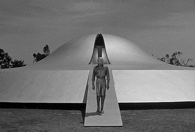
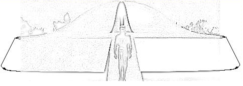
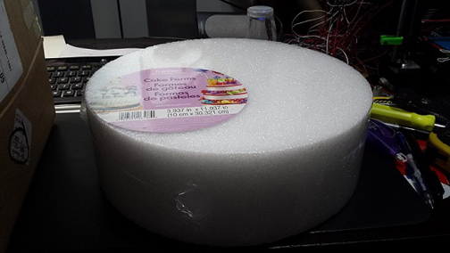
In this study, we will try to determine the appropriate dimensions for the UFO. To meet the customer’s requirement that it should look like the UFO from the movie, the day the earth stood still, we worked off of the picture (shown below) that he thought best represented the UFO from that movie.

 juan2

Using that as our guide, we modified the picture, using the free drawing software called GIMP, to include the remaining parts of the UFO and to try to extract only the edges from the UFO as shown below.

juan3

juan4

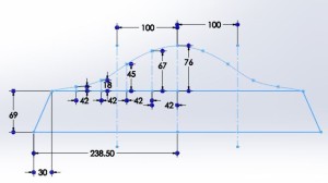
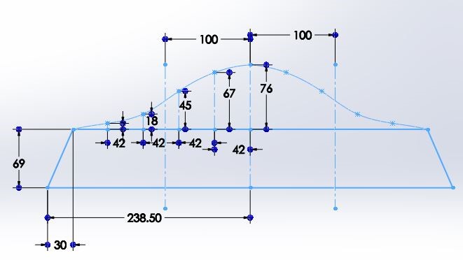
Once we had that complete model, we were able to extract the measurements from the drawing itself by measuring the amount of pixels this drawing took up in for certain areas. Below we show the measured out areas.


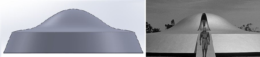
Now to visually compare the original picture with our measured 3D model we have:

These two look approximately the same, we can increase the number of points used to get the top portion of the dome to get shape more accurately if needed.

Now that we know we have the correct shape, we will want to resize the dimensions to get realistic measured values.

We currently have:

X=length of base=477 pixels

Y=height of UFO=145 pixels

X1= length of 2nd base = 417 pixels

Y2= height of dome from 2nd base=76 pixels

Y1= height base=69 pixels

Dz= distance between curve points=45 pixels

Zi= height of curvature from 2nd base=7, 18, 45, 67, and 76 pixels

R= radius of dome=100 pixels

We will extract the ratios of lengths based on the length of the base therefore we will have:

T= total Height/length ratio:

Y/X= 145/477=0.3040

B= base 2 to dome ratio:

R*2/X1= 200/417=0.4796

YY= Height/height ratio:

 Y1/Y, Y2/Y= 69/145, 76/145= .4759, .5241

RX=radius/length:

 R/X= 100/477= 0.2096

Zy= ratio of height curvatures:

 Z/Y2= 7/76, 18/76, 45/76, 67/76= .0921, .2368, .5921, .8816

Angle between two bases:

Arctan(Y1/((X-X1)/2))= arctan(69/30)=   66.5 degrees

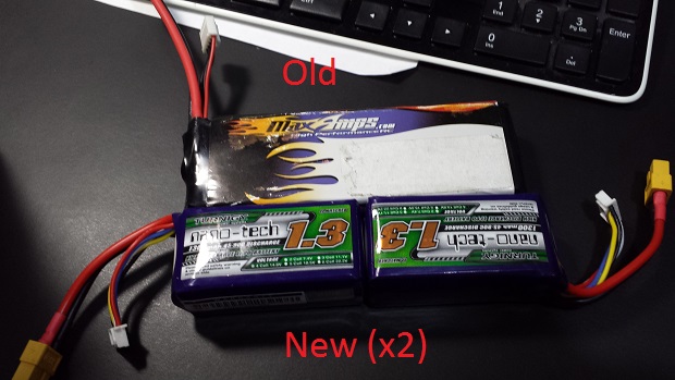
Given the 50 mm fans from the customer, we would like to construct the appropriate dimensions for this UFO. To keep the same shape as the UFO, we would like to mount the fans in the relatively flat part of the second base. Therefore we have:

Fan= 53 mm (59mm at the top)

53+53mm = x1-2*R= 106mm (108mm), since we know B, we can determine X1,

X1= 106/(1-B)= 203.7 mm +/- 10mm     (226.74mm)

Since we know x1, we can find the radius of the dome

R= x1*B/2= 48.8 mm +/- 10 mm         (54.37mm)

Since we know R, we can find the Base/total length of the ufo:

X= R/RX= 233.03 mm +/- 10 mm =9.17 inches          (259.39mm =10.21in)

Since we know X, we can find the heights of this UFO, which we get:

Y= X*T= 70.84 mm +/- 10 mm      (78.86mm)         

Y1=Y*yy1= 33.71 mm +/- 10 mm      (367.53mm)

Y2=         Y*yy2=  37.13 mm +/- 10 mm      (41.33mm)

Since we know Y2, we can find the ratio of height curvatures:

Zi= Y2*Zy= 3.41, 8.79, 21.98, 32.73 mm +/- 5 mm (3.8,9.7,24.47,36.43mm)

Thus now we have all the dimensions we need to create this 3D model.

Appendix A:

The requirement of landing on the hand was considered previously. In consideration of the future, which may change the fans, here is a brief discussion on the dimensions using that requirement:

To land on one’s hand, the base of the UFO must be proportional to the size of the customer’s hand. Using the average hand size for a male, 189×84 mm, and assuming the UFO would be lightweight (as determined by the Number of Fans test, no more than 1104g), the UFO would be reasonably land on the hand as long as the diameter is no larger than 1.5xsize of the hand.

1.5×189=283.5 mm (UFO diameter based on hand length)

1.5×84= 126 mm (UFO diameter based on hand width)

Taking the average of the two above would yield 204.8 +/- 20 mm (8.06 in) UFO max length. Once we know the diameter of the UFO, the rest would follow using the ratios mentioned above.

Thus, we determined the dimensions of this UFO, however, there is a safety issue in considering the fans. Using the provided 50 mm fans, part of the fans would be in the way, making it unable to land on one’s hand. We can resolve that issue by making it larger, however, that would also not land on one’s hand reasonably (it would become a balancing act). Besides switching out the fans with some smaller fans, there are two methods we will mention to try to resolve this issue.

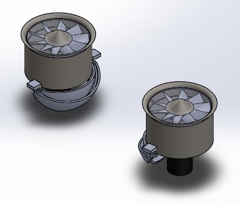
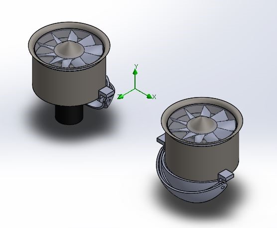
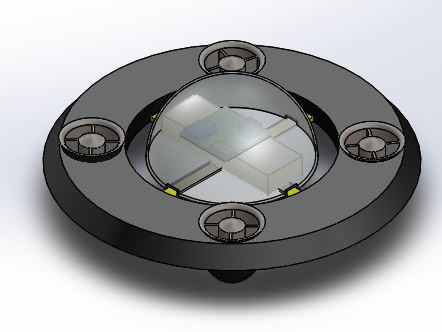
Our first idea would be to separate the fans away from the area from which the UFO would land on. That is, we create two sections: land section, and fan section. Below we show an example of such a model:

juan5

The land section would have to be on the area where the center of mass is located, ensuring the UFO would land on the hand. The dimensions of that area are similar to before. The fan area would have to be separated from the land section by at least half an index finger length (average would be 4 inches for index finger length) in consideration of safety. The fan section itself, would only need to be as large as the fans themselves, the rest would follow while taking into consideration the UFO model from the movie (which the picture above does a terrible job at). We can make this separation visible only from the bottom to preserve the UFO’s original look if necessary.

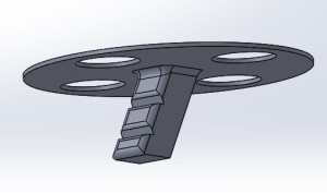
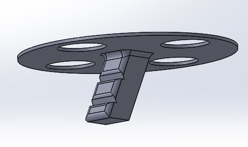
Our other idea would be implement some landing gear, namely the exit. We can include an exit stair case beneath the UFO which would serve as the place where the customer would hold onto the UFO. The inclusion of landing gear (which the customer expressed a want for), would allow the UFO to land on a flat surface as well. The length of such hand held exit would have to be around the width of the hand which is 89mm. Taking into consideration the height of the UFO would be around the same, we would have to implement ways of making that shorter, however the idea behind that would look like this:

juan6

New Components, Part 3

By Tuan Vo, Project Manager

Material of aircraft:
To build the body of the aircraft, we have decided to go with plastic foam.  A 12”diameter X 4”high wheel of foam weighs in at 98grams.  We will cut the foam to mount the fans and components using a hot knife. In this project, one of the basic and most important requirement is to make the aircraft look like a UFO.  Foam would be ideal when considering cost, weight, and level of skill during fabrication. 
 
03
 
The outside shell will have to be lightweight yet rigid enough to protect the aircraft.  There are two materials we can use that has the two characteristics: fiberglass and carbon fiber.  Both materials will have to be molded with a resin and hardener chemical reaction. 
 
Below is a qualitative comparison between fiberglass and carbon fiber, taken from Fibre Glast Company.
 
The legend is as follows: P=Poor, F=Fair, G=Good, E=Excellent.
 
04
 
Although the cost of production for carbon fiber is higher than fiberglass, the stiffness to weight ration of carbon fiber is superior.  Weight reduction is what we need, and the cost to produce the parts for this aircraft is not too big and within budget.
 
The carbon fiber we are using is 2×2 twill woven with thickness of .012 inch thickness. One sheet of CF should be able to provide the rigidity we need.  However, we will be using two layers just to ensure
 

New Components, Part 2

By Tuan Vo, Project Manager

Battery:
When picking the battery, three requirements must be taken into consideration.  1) the battery must have enough power to run the fans for the required amount of time.  2) the discharge rate must be high enough to provide the fan with required current to operate. 3) weight must be minimal.

 The battery provided used by the last group is a big 3250mAh with 150C discharge rate giving constant amperage of 487.5A.  According to the motor battery study (see blog) by Jake Rice, this battery is more than enough to power 4 fans for the required time.  However, the battery was selected with 6 fans in mind and is too big and heavy, weighing in at 327grams.  We can reduce the battery size with any combination of batteries that meet the power requirement.  One battery powering all 4 fans or two batteries powering 2 fans each are the simplest and most logical way of powering our fans.

In order to fit the battery into the body of the aircraft, it is easier to use two smaller batteries instead of one bigger batteries.  We’ve decided on two smaller LiPo batteries from HobbyKing. 

Chosen: Turnigy LiPo battery (4S or 4cell).  1300mAh 45-90C, max 100C. 14.8V. (HobbyKing, Malaysia).

This battery can power two motors which draw current at a maximum theoretical 27*2=54A.  At minimum, this battery can output 1.3Ah*45C=58.5A which is enough even for max current draw.    According to last project’s current draw study, two fans would draw current at 11.17A*2=22.34A; to run this for two minutes we would need a battery of size 745mAh. (Current*time)  The 1300mAh battery capacity would give us an extra 42.7% capacity over minimum.

The weight of two batteries is 155grams*2=310grams, which is 17 grams less than the MaxAmps battery used by last semester.  We shaved off some weight without spending too much money.  These two new batteries cost a total of 45$ including shipping.

02

New Components, Part 1

By Tuan Vo, Program Manager

Introduction:
Weight is the number one factor when determining our components that will be used on our aircraft. As stated in the Preliminary Design Document, we decided to use the fans and speed controllers given to us.

Purpose: To identify and expatiate on the equipment and materials selected for the aircraft.

  1. Microprocessor:

We had a choice of several microprocessors that are lightweight enough and can provide the processing functionality required for flight. The last team to work on this project utilized the TinyDuino which is produced by tiny-circuits.com.  The TinyDuino processor board was used in conjunction with a USB and ICP shield and protoshield.  All together this set up costs 40$.  The processing is the specification provided by tiny-circuits.com.

  • Atmega328P processor (same as is used on the Arduino Uno)
  • Reset switch
  • Status LED
  • 8MHz ceramic resonator
  • Optional battery connector for CR1612-CR1632 coin cell batteries
  • External power supported with a 0.1″ power connection holes
  • Supports automatic switching between +5V and VBATT (if +5V is present, it will be used instead of the battery)

This TinyDuino setup was provided to us by the customer because it was utilized by the last group to take on the vertical take-off and landing aircraft.  However, the last group could not power the TinyDuino using USB alone.  There appears to be hardware damage when we received the stack of boards.  It constantly need a coin cell battery in there just to be able to power on.  Power was not the main factor that inhibited this team from recycling the TinyDuino for this build, it was the fact that we could not program with it.  No one in the company knew how to communicate with the TinyDuino, and we have tried asking tiny-circuits.com for support to no avail.  The last team to use it also documented significant difficulty while programming it, although they left us no help on how to establish a connection in the first place.  One problem could be that the TinyDuino was structurally compromised, and we could buy a new one to find out if it’s an isolated case.  However, the cost of the whole setup is $40 dollars, so we decided to explore other options. 

The Arduino Uno is a good board to use; it uses the same ATmega328P that the TinyDuino uses.  However, we cannot use this reliable board because at 28 grams it is too big and heavy. The Arduino Pro Mini and Mini series are smaller versions of Arduino Unos, weigh only 4 grams and are much, much smaller in size.  However, the consensus on quadcopter forums is that the Pro Mini and Mini are troublesome to work with and have a reputation of failing more frequently.  

The final board we have decided on is the Arduino Nano.  The Nano is very similar to the Uno and Pro Mini, weighs in at 4 grams, and has been proven reliable in the past.  In fact, one of our team member has used the Nano in his EE444 class where it was used on a robotic rover.  The Nano runs off of 5V battery source which could be provided by the onboard Battery Eliminator Circuit (BEC) of one of the speed controller. Below is the provided specification for the Arduino Nano.  It has 14 I/O pins which is more than enough control outputs for PWM purpose.  At $10 dollars each, the Nano is a good choice.

01 

Microcontroller ATmega328
Operating Voltage (logic level) 5 V
Input Voltage (recommended) 7-12 V
Input Voltage (limits) 6-20 V
Digital I/O Pins 14 (of which 6 provide PWM output)
Analog Input Pins 8
DC Current per I/O Pin 40 mA
Flash Memory  32 KB (ATmega328) of which 2 KB used by bootloader
SRAM 2 KB (ATmega328)
EEPROM 1 KB (ATmega328)
Clock Speed 16 MHz
Dimensions 0.73″ x 1.70″

Parts list and projected cost


By Tuan Vo, Project Manager 

Quantity Name Purpose Cost per unit Vendor
1 Arduino Nano Microcontroller $17.50  (Amazon)
1 Epoxy-Resin for Carbon Fiber Build structure $32


(Ebay,polymerproducts)


2 Carbon Fiber Carbon Fiber Cloth Fabric Plain Weave 50″ 12k 300gsm Build structure $47 Ebay, elitemotoring)


1 Electric Styrofoam cutter Build Structure $39 Ebay- jossynicky0806)


1 Magic-Sculpt self-hardening epoxy modeling clay 1 lb. Build Structure $28.5 (Ebay,artplace)


2 Foam block Build Structure $30 (Michael’s Arts)
20 Connectors (Generic and assorted) Interface $30(total) JK Electronics
1 Switch Safety on/off $3 JK Electronics
2 Perforated board Connection and interfacing $7 JK Electronics


Total=$234


Schedule (from beginning of project)
6

Tasks (by team member):

Tuan Vo: Build Body, integrate subsystems, assemble body, test microcontroller, develop safety cutoff, prototype connections and general electrical assembly.

Jake Rice: Test IMU, develop control codes, test control of flight, interface communications with control.

Juan Motano: 3D modelling (omitted from schedule), develop communications, test communications, develop communication code, interface communication with control.

Resource Report

By Tuan Vo, Project Manager


The weight of the aircraft must be of proportion to the amount of thrust the propulsion components can support.  This resource reports defines resource as all components, power, and mass requirements related to the aircraft.

Study by Juan Montano on components and mass provides us with total mass when powered by 4 fans.  Note the structure mass is estimated based on a previous model hexacopter using all the same components except the Tinyduino controller and number of fans. Also at the time of writing this document, the two batteries are being shipped. 

Part/#fans Measured weight (total)
Fan (4) 460g
ECS(4) 120g
Battery* 380g
Structure** 298g
XBee 7g
Arduino Nano 8g
IMU 2g
Components (excluding the body) 977g
Total: 1275g


Power resource: 

Part Voltage(V) Current
Electric Fan 14.8 16.5A @ 100% thrust
Arduino Nano 5V NA
XBee 2.8-3.4V NA
IMU 3.3V 10mA
LiPo 4s 14.8 14.8V 1300mAh (2600mAh total)
9V battery 9V 500mAh

* The Arduino Nano, XBee, and IMU operates under 50mAh which is negligible considering the current draw of the fans is many thousand times larger.


Task Description 

  • Receive parts from customer.
  • Evaluate parts for functionality. Make lists of parts needed.
  • Determine system requirements from mission objectives obtained from the customer.
  • Establish model of the aircraft using 3D modelling.  Create major components needed such as fans, microcontroller, and power source.
  • Write a Preliminary Design Document to give to customer to obtain funding.
  • Purchase parts.  Work with programming the microcontroller and wireless communication device, XBee, while waiting for parts to arrive.
  • Build a remote control device to receive user input and transmit via XBee to the microcontroller.
  • Build the body of the aircraft.  Cut the foam for the middle section and mold carbon fiber for the top and bottom piece.  Cut out as necessary.
  • Do systems tests that can be done without mounting the fans onto the body.
  • Mount fans onto the body and carry out the rest of the system tests.
  • Final adjustments to programming and structure based on tests.
  • Final presentation to the customer.

Level 2 Requirements

By Tuan Vo and Elaine Doan

Structural Subsystem Requirements

  1. The VTOL will use four 55 mm electric ducted fans per the request of the customer. The four fans gives enough thrust to lift themselves, the required electronics for control, and a body.  The body is estimated to be 298g from the fan selection study by Juan Montana and will give control of 36.5% thrust control. Using a margin of 15% for the mass of the body, we conclude that the body of the aircraft, not including any electrical components, must weigh less than 343g.
  2. Weigh the body and ensure this does not exceed 343g.
  3. After mounting all hardware and body along with the four fans, run the fans at 63.5% thrust.  The VTOL must achieve takeoff at this point.

Wireless Communication Requirements

  1. To wirelessly control the VTOL from a minimum range of 40ft, the VTOL system will include the XBee wireless RF module (maximum range of 100m or 300 ft.). The transmitter of the XBee wireless RF module will be connected to the remote control. The receiver of the XBee wireless RF module will be connected to the Arduino.
  2. Perform communication testing of the XBees using X-CTU. Make sure the “Baud Rate” of both the transmitter and receiver match each other. (https://sites.google.com/site/xbeetutorial/xctu).
  3. Using the remote control, command the VTOL to move forward, backward, up, down and side to side. The range of communication must be at least 40ft. 

Control System Requirements

  1. To achieve flight at the elevation of 8ft, four electronic speed controls will be used to increase and decrease the speed of each fan by 20% at a reference of 63.5% lift off thrust.
  2. Write a test code using the Arduino Nano to control the speed controllers and monitor it as it run at lift off thrust. Determine if the VTOL reaches desired height by comparing with an obstacle or measurement. The VTOL must stay at desired height with a deviation of 1/2 feet. 
  3. Raise or lower the speed of each fans individually by +/- 20% thrust.  Watch and confirm expected desirable increase or decrease in fan rpm.  This increase and decrease determines the VTOL’s directional movement.
    1. To support flight around the ECS 317 room, the VTOL will use the inertial movement unit. The inertial movement unit includes an accelerometer and gyroscope that will prevent the VTOL from undesired tilting, drifting or flipping during the flight around the room.  The inertial movement forms a closed loop control system that will stabilize the VTOL throughout its flight around the ECS 317 room. 
    2. Create a test program using the Arduino that will monitor the amount of tilt and acceleration present as the IMU is moved.
      1. To achieve flight (vertical lift off), weight is a major concern; as a result, the microprocessor of the VTOL will be the Arduino Nano.  The Nano weighs only 4 grams and at the same time its I/O ports are accessible to support four fans and receive inputs from both the user and the IMU.
      2. Specs of the Arduino can be verified at the link provided below: http://arduino.cc/en/Main/arduinoBoardNano#.UylKA_ldXGA

Power System Requirements

To provide enough power for the VTOL to fly around the ECS 317 class once (85.75 ft.), the main motor battery(s) must provide a minimum 1489 mAh to sustain required flight time. This will provide the speed controls and consequently the fans with enough power to provide 70% thrust for 2 minutes. The batteries chosen are two 1300mAh LiPo batteries.  Two speed controllers and two fans will be connected to one battery. 

  1. Verify at battery study and mAh ratings link: https://www.arxterra.com/motor-battery-selection/
  2. Before testing the batteries in actual flight, hook up the batteries to their specified fans.  On full charge, have the batteries power the fans at 70% thrust and record time from full to empty, signified by when any of the fans start to reduce in rpm. Time recorded must be longer than two minutes minimum flight time. 

 System Block Diagram
4


System Interface
5


Level 1 Requirements

Level 1 Requirements – By: Tuan Vo and Elaine Doan

  1. The VTOL will be designed with a flat conical frustum base and a dome (semi-sphere) attached at the top center of the conical frustum to model after the UFO from the movie, The Day the Earth Stood Still.
    1. Compare the 3D drawing created by team to a picture of the UFO, approved by the customer.
  2. The VTOL will fly once around the ECS 317 room (The room is measured to be 30 ft. wide and 23 ft. long. Assuming an oval flight path, distance to be travelled is 86.75 ft.)
    1. Test: Erect a perimeter with the same square dimension as room ECS 317.  Fly the VTOL aircraft around the inside perimeter one time.
  3. For safety and to avoid contact with people, the VTOL aircraft will fly at minimum elevation of 8ft from the ground.
    1. Test: Use measuring tape to indicate on the wall where 8ft is. Achieve vertical takeoff and hover the machine at 8ft, indicated on the wall.  Control and move the VTOL aircraft around and make sure that the elevation remains at 8ft with deviation of 0.5 ft. or less for the duration of flight.
  4. The VTOL will be controlled wirelessly from the minimum range 40 ft. (the distance from one wall to the opposite wall of the ECS 317 room).
    1. Test: Stand at one end of the ECS 317 classroom and wirelessly control the VTOL across the room to the opposite wall.