Spring 2018: Project BiPed: Verification and Validation Pass/Fail Matrix
By: Jeffrey De La Cruz (Mission, Systems, and Test Engineer)
Verified By: Miguel Gonzalez (Project Manager)
Approved By: Miguel Garcia (Quality Assurance)
Table of Contents
Introduction
The Level 1 and Level 2 requirements verification pass/fail matrix will demonstrate if the BiPed functions properly. Each requirement state will be tested by a specific verification method. The verification methods consist of Test, Analysis, Demonstration, and Inspection. As project BiPed continues, the results tools, procedure, and results section will be filled depending on the level requirement. This will determine whether the level requirements pass or fail the verification. The Level 1 and Level 2 requirements are separated in order.
Purpose
The purpose of this document is to provide a comprehensive Verification and Validation (V&V) Test Plan of the Spring 2018 Micro FOBO, including the Project ConOps/Mission, Test Methodology, Verification and Validation Matrices, and Test Cases.
Project ConOps/Mission
The mission is to create a toy robot that can be controlled and navigate the toy robot through a 2D maze. The toy robot would then be capable to travel through the maze repeating the same route from its first walkthrough of the maze.
Document Overview
This document is organized as follows:
- Section 2 contains links to relevant and applicable project reference documents and presentations for this Test Plan.
- Section 3 contains a description of the Testing Methodology utilized in this Test Plan, including the Master Verification and Validation Matrix, a description of the 4 types of V&V testing performed, the Test Environment(s) description(s), and a Master Test Case List of all (number #) Test Cases for this project.
Applicable Documents
This section contains a table of all relevant and applicable project reference documents and presentations for the Micro FOBO Spring 2018 Verification and Validation Test Plan.
| Document Name | Document Description | Document Link |
| Research for Micro FOBO | Contains research for Micro FOBO. Links to documents helpful to work on Micro FOBO. | Research |
| Project BiPed Website | Contains information regarding Jonathon Dowdall’s FOBO | FOBO |
| PDD | Preliminary Design Document. Contains xxxxxx | PDD |
| PDR | Preliminary Design Review Presentation. Contains L1 and L2 Requirements, System Block Diagram, Resource Allocation Reports, trade studies,xxxxxx | PDR |
| Final Project Summary | Final Presentation of completed Project. Contains xxxxxx | Currently not available |
| NASA Systems Engineering Handbook (2007) | Document containing Test Methodologies in Section 3 | http://www.acq.osd.mil/se/docs/NASA-SP-2007-6105-Rev-1-Final-31Dec2007.pdf |
Testing Methodology
This section contains the Master Verification and Validation Matrix, as well as detailed descriptions of the various Test Methods and Test Cases utilized in this Test Plan.
Master Verification and Validation (V&V) Matrix
This matrix provides complete traceability of every requirement. Specifically, every requirement is mapped to its description, success criteria, V&V testing designation and method, and Test Case(s) where the requirement will be tested. Note that some overlap between Test Cases’ requirements V&V is okay.
Level One Requirements
| Requirement Number | Requirement Text | Verification Success Criteria | Verification Method (Test, Analysis, Demonstration, Inspection) | Test Case # |
| L1-1 | Micro FOBO will stand on its own without any physical help. | Micro stands on its own without any assistance. | Inspection | 2 |
| L1-2 | Micro FOBO’s electronic components will be easily assembled and disassembled from the robot’s head. | Micro FOBO’s electronic components are easily assembled and disassembled from the robot’s head | Inspection | 2 |
| L1-3 | Micro FOBO will have 2 legs | Micro FOBO has two legs. | Inspection | 2 |
| L1-4 | Micro FOBO will be a toy robot based on the design of the FOBO from Jonathan Dowdall. | Micro FOBO is a toy robot based on Jonathan Dowdall | Inspection | 1 |
| L1-5 | Micro FOBO will fit within the classroom cabinets. 28”x13”x14.5” | Micro FOBO fits in the cabinet within those dimensions | Inspection | 5 |
| L1-6 | Micro FOBO will utilize a 3DoT board or Sparkfun Pro Micro 3.3V/8MHz. | Micro FOBO utilizes a 3DoT board or Sparkfun Pro Micro 3.3V/8MHz | Inspection | 2 |
| L1-7 | Micro FOBO’s part components will be 3D printed using the material carbon fiber PLA | Micro FOBO’s parts are 3D printed using carbon fiber PLA | Inspection | 1 |
| L1-8 | Micro FOBO will not exceed a print time of 7.80 hours. Upon approval of waiver | Micro FOBO does not take longer than 7.80 hours to print. | Inspection | 1 |
| L1-9 | Micro FOBO shall not exceed a cost of $250.00 to construct. | Cost does not exceed $250.00 | Inspection | 5 |
| L1-10
|
Micro FOBO shall be 63% of the overall size of Jonathan Dowdall’s FOBO. | Micro FOBO is smaller than original FOBO by 63% or less
|
Inspection/Analysis
|
2 |
| L1-11 | Micro FOBO shall detect intersections of the maze. | Micro FOBO detects intersections of the maze. | Demonstration | 3 |
| L1-12 | Micro FOBO shall be able to perform static walking | Micro FOBO performs static walking | Inspection | 3 |
| L1-13 | Micro FOBO shall produce a 90-degree turn. | Micro FOBO turns | Demonstration | 3 |
| Requirement Number | Requirement Text | Verification Success Criteria | Verification Method (Test, Analysis, Demonstration, Inspection) | Test Case # |
| L1-14 | The user shall guide the Micro FOBO through the maze with the use of the Arxterra application. | The user guides the Micro FOBO through the maze using the Arxterra application | Demonstration | 3 |
| L1-15 | Micro FOBO shall record the path of the maze | Micro FOBO records the path of the maze | Demonstration | 3 |
| L1-16 | Micro FOBO shall traverse the maze using the recorded path. | Micro FOBO traverses the maze using the recorded path | Demonstration | 3 |
| L1-17 | Micro FOBO shall traverse cloth, paper, and linoleum. | Micro FOBO walks on cloth, paper, and linoleum. | Demonstration | 4 |
| L1-18 | Micro FOBO will utilize a printable circuit board. | Micro FOBO utilizes a printable circuit board. | Inspection | 2 |
| L1-19 | The final biped shall be physically completed by May 10, 2018 | Micro FOBO is physically completed by May 10, 2018 | Inspection | 1 |
| L1-20 | Micro FOBO should step over a square rod 1cm tall by 1cm wide by 10 cm long | Micro FOBO steps over a square rod of 1cm tall by 1cm wide by 10cm long. | Demonstration | 4 |
| L1-21 | Micro FOBO should be able to perform dynamic walking. | Micro FOBO performs dynamic walking | Demonstration | 3 |
Level Two Requirements
| Requirement Number | Requirement Text | Verification Success Criteria | Verification Method (Test, Analysis, Demonstration, Inspection) | Test Case # |
| L2-1 | Micro FOBO will be connected via Bluetooth to the app on an android phone | Micro FOBO connects via Bluetooth | Demonstration | 3 |
| L2-2 | Micro FOBO dimensions of robot will need to be small enough to fit in a 4in by 4in box for maze purposes. | Micro FOBO fits in the 4in by 4in square of the maze. | Inspection | 5 |
| L2-3 | Micro FOBO will use eight micro servos. | Micro FOBO has eight micro servos | Inspection | 2 |
| L2-4 | Micro FOBO will use UV sensors to detect the colors of the maze. | Micro FOBO UV sensor detects the colors of the maze | Demonstration | 2 |
| L2-5 | By detecting the colors of the maze, the Micro FOBO shall determine if it is at an intersection. (intersection detection) | Using the colors of the maze, Micro FOBO detects an intersection | Test | 3 |
| L2-6 | Micro FOBO shall use a battery that outputs 3.7V | Test | 2 | |
| L2-7 | The user shall use the Arxterra application to move the robot forward, left, and right. | Micro FOBO moves forward, left and right. | Test | 3 |
| L2-8 | Micro FOBO’s wiring shall be able to connect and reconnect in 10 min or less | The wiring for Micro FOBO’s connects in 10 min or less. | Inspection | 1 |
| Requirement Number | Requirement Text | Verification Success Criteria | Verification Method (Test, Analysis, Demonstration, Inspection) | Test Case # |
| L2-9 | Micro FOBO wiring shall be nice and clean with the usage of terminal blocks, contact pins, 2.0mm PH series JST connectors, and barrel connectors | Micro FOBO’s wiring is nice and clean using terminal blocks, contact pins, 2.0mm PH series JST connectors, and barrel connectors. | Demonstration/inspection | 1 |
| L2-10 | Micro FOBO shall play a musical tune when the maze is completed | Micro FOBO plays a musical tun when the maze is completed. | Inspection | 4 |
| L2-11 | Micro FOBO shall have indicating LEDs to demonstrate if micro FOBO is on. | Micro FOBO has LEDs and the LEDs turn on. These LEDs indicate whether its on. | 2 | |
| L2-12 | Micro FOBO shall record the path of the maze the Micro FOBO traverses on the 3DoT board or the Sparkfun Pro Micro 3.3V/8MHz to navigate the robot through the maze. | Micro FOBO records the path of the maze and navigates micro FOBO through the maze. | Demonstration | 3 |
| L2-13 | Micro FOBO shall use a 3D printed carbon fiber PLA head chassis and leg components. | Micro FOBO’s head chassis and leg components are 3D printed using the carbon fiber PLA. | Inspection | 1 |
| L2-14 | Micro FOBO shall measure 4.5” x 3.25” x 7.25” (l x w x h) | Micro FOBO measures 4.5” x 3.25” x 7.25” (l x w x h) | Inspection/Analysis | 2 |
| L2-15 | Micro FOBO shall weigh 460g | Micro FOBO weighs at or near 460 grams. | 2 | |
| L2-16 | Micro FOBO shall detect objects 8 inches from it. | Micro FOBO detects an object 8 inches from it | Demonstration | 3 |
| L2-17 | Micro FOBO should be able detect other robots and avoid collision. Micro FOBO should stop completely and wait for command | Micro FOBO detects other robots in the maze and stops. It stops and awaits command. | Demonstration | 3 |
| L2-18 | Micro FOBO should take a bow at the end of the maze. | Micro FOBO takes a bow at the end of the maze. | Demonstration | 4 |
Testing Types and Methods
This subsection contains the 4 types of Verification and Validation (V&V) testing, as derived from the NASA Systems Engineering Handbook referenced above in Section 2. The material is taken from Chapter 5 in the NASA Handbook and replicated below.
Verification proves that a realized product for any system model within the system structure conforms to the build-to requirements (for software elements) or realize-to specifications and design descriptive documents (for hardware elements, manual procedures, or composite products of hardware, software, and manual procedures). In other words, Verification is requirements driven; verification shows proof of compliance with requirements; that the product can meet each “shall” statement as proven through a performance of a test, analysis, inspection, or demonstration.
Validation is conducted under realistic conditions (or simulated conditions) on an end product for the purpose of determining the effectiveness and suitability of the product for use in mission operations by typical users; and the evaluation of the results of such tests. Testing is the detailed quantifying method of both verification and validation. However, testing is required to validate final end products to be produced and deployed. In other words, Validation is ConOps/Mission-driven; validation shows that the product accomplishes the intended purpose in the intended environment; that product meets the expectations of the customer and other stakeholders as shown through the performance of a test, analysis, inspection, or demonstration.
Verification by Analysis
The use of mathematical modeling and analytical techniques to predict the suitability of a design to stakeholder expectations based on calculated data or data derived from lower system structure end product verifications. Analysis is generally used when a prototype; engineering model; or fabricated, assembled, and integrated product is not available. Analysis includes the use of modeling and simulation as analytical tools. A model is a mathematical representation of reality. A simulation is the manipulation of a model.
Verification by Demonstration
Showing that the use of an end product achieves the individual specified requirement. It is generally a basic confirmation of performance capability, differentiated from testing by the lack of detailed data gathering. Demonstrations can involve the use of physical models or mockups; for example, a requirement that all controls shall be reachable by the pilot could be verified by having a pilot perform flight-related tasks in a cockpit mockup or simulator. A demonstration could also be the actual operation of the end product by highly qualified personnel, such as test pilots, who perform a one-time event that demonstrates a capability to operate at extreme limits of system performance, an operation not normally expected from a representative operational pilot.
Verification by Inspection
The visual examination of a realized end product. Inspection is generally used to verify physical design features or specific manufacturer identification. For example, if there is a requirement that the safety arming pin has a red flag with the words “Remove Before Flight” stenciled on the flag in black letters, a visual inspection of the arming pin flag can be used to determine if this requirement was met.
Verification by Test
The use of an end product to obtain detailed data needed to verify performance, or provide sufficient information to verify performance through further analysis. Testing can be conducted on final end products, breadboards, brass boards or prototypes. Testing produces data at discrete points for each specified requirement under controlled conditions and is the most resource-intensive verification/validation technique. As the saying goes, “Test as you fly, and fly as you test.” (See Subsection 5.3.2.5.).
Validation by Analysis
The use of mathematical modeling and analytical techniques to predict the suitability of a design to stakeholder expectations based on calculated data or data derived from lower system structure end product validations. It is generally used when a prototype; engineering model; or fabricated, assembled, and integrated product is not available. Analysis includes the use of both modeling and simulation.
Validation by Demonstration
The use of a realized end product to show that a set of stakeholder expectations can be achieved. It is generally used for a basic confirmation of performance capability and is differentiated from testing by the lack of detailed data gathering. Validation is done under realistic conditions for any end product within the system structure for the purpose of determining the effectiveness and suitability of the product for use in NASA missions or mission support by typical users and evaluating the results of such tests.
Validation by Inspection
The visual examination of a realized end product. It is generally used to validate physical design features or specific manufacturer identification.
Validation by Test
The use of a realized end product to obtain detailed data to validate performance or to provide sufficient information to validate performance through further analysis. Testing is the detailed quantifying method of both verification and validation but it is required in order to validate final end products to be produced and deployed.
Master Test Case List
A Test Case can be described as a scenario containing a sequence of detailed test steps, in order to perform verification/validation testing on multiple requirements that are similar in nature.
For example, if a group has multiple requirements regarding starting up their robot project, they can group all these requirements to be verified/validated in a single test case. Similarly, if a group has multiple requirements that can be verified/validated via inspection, they can group all of them together in a single test case.
The purpose of this subsection is to provide a High-Level overview of all Test Cases utilized in this Test Plan. Each item in this subsection will contain the following: Test Case Number and Name, High-Level Scenario Description, and Test Environment Description.
TC-01: Creation, Construction, and Completion of Micro FOBO
Description: Micro FOBO is a toy biped robot based on the design of Jonathon Dowdall’s FOBO. Micro FOBO will be 3D printed using the carbon fiber PLA and will not exceed a print time of 7.80 hours. The head chassis and leg components will be 3D printed using this material. Micro FOBO’s wiring connection does not take more than 10 min and it will contain the usage of terminal blocks, contact pins, 2.0mm PH series JST connectors and barrel connectors. The final physical rendition of micro FOBO shall be completed by May 10, 2018. This test case describes the creation, construction, and completion of micro FOBO. The design, the material used on the components, the print time and the date is described in this test case. These requirements are grouped together because of the conditions of the creation and completion of micro FOBO.
Test Environment: The test case takes place in a classroom.
TC-02: Physical Attributes of Micro FOBO
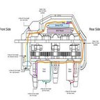
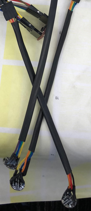
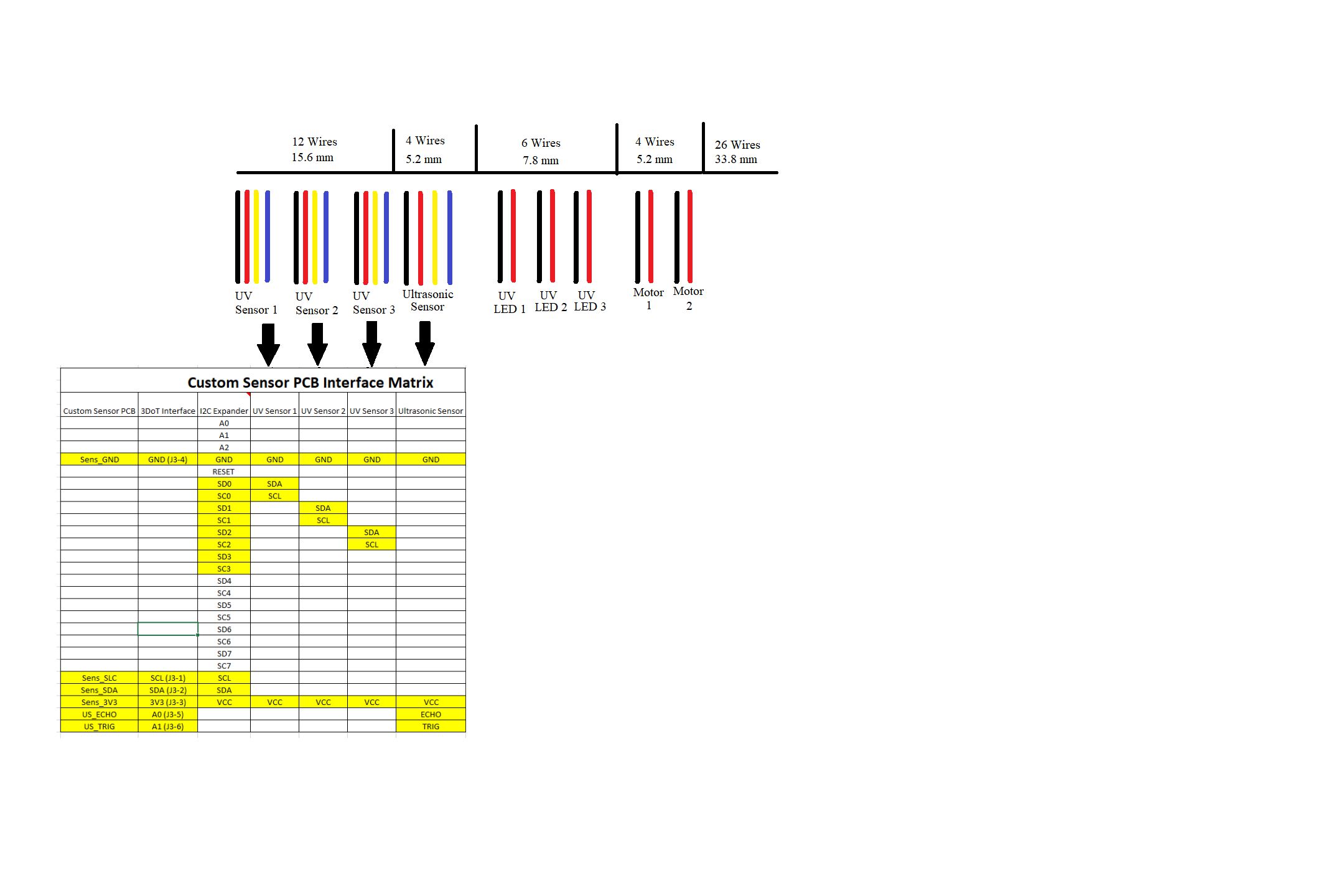
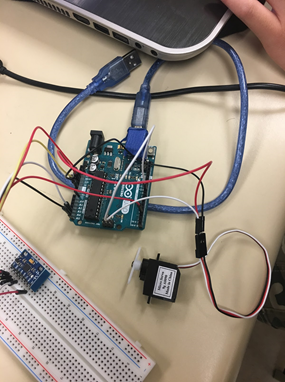
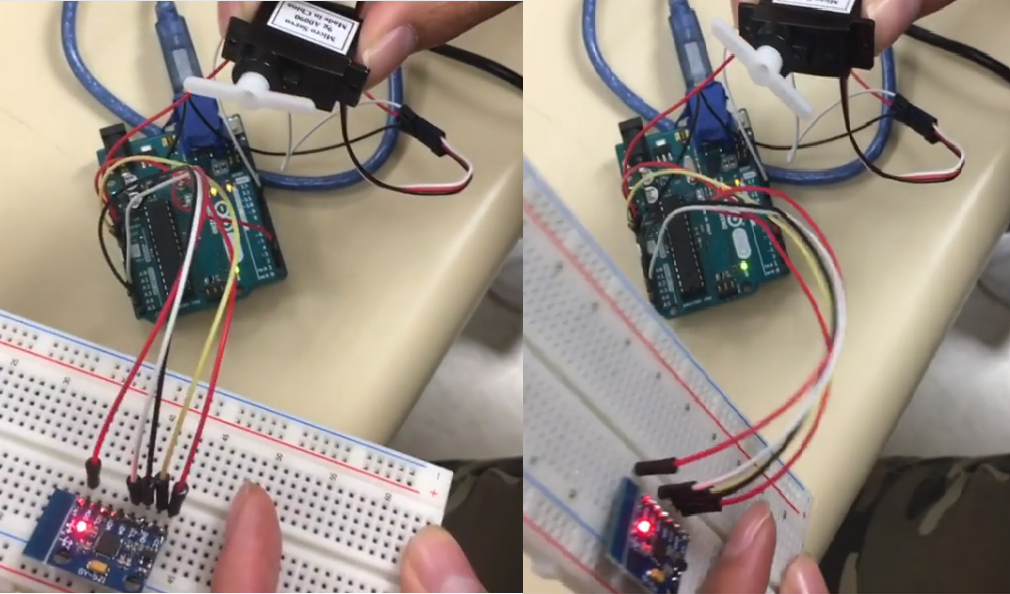
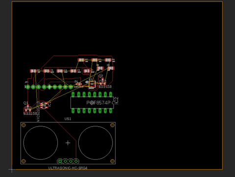
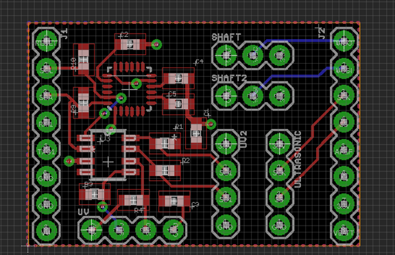
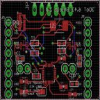
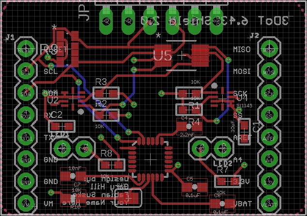
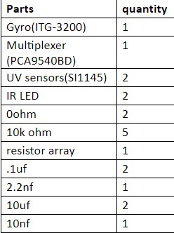
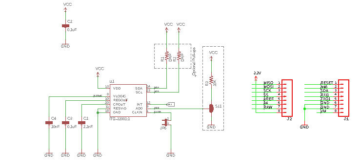
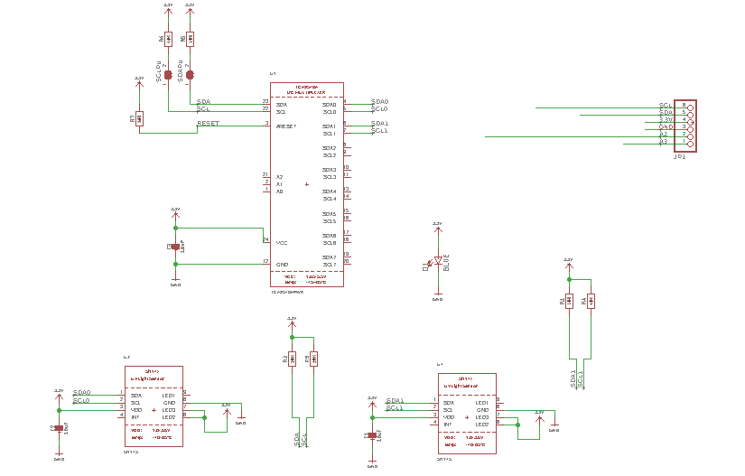
Description: This test case consists of anything physical attributes of the micro FOBO. While the previous test case discusses the creation and completion of micro FOBO, this test case will include the requirements that micro FOBO has physically. Micro FOBO electronics components will be easily assembled and disassembled. It will contain two legs that will help it stands on its own without any physical help from the group. A total of 8 servos will be in the legs. Micro FOBO overall size is about 60% of the overall size of Jonathon Dowdall’s FOBO. The dimensions of micro FOBO are: 4.5”x3.25”x7.25”(l x w x h). On the left and right side of micro FOBO’s head, it will contain one LED on each side to indicate whether its turning left or right. Micro FOBO will include a UV sensor to detect colors, will include a custom PCB for sensors and servos, a battery that outputs 3.7 V, a 3DOT board or Pro Micro 3.3V/8MHz. Micro FOBO weight will not exceed 460g. These are grouped together because these are qualities of micro FOBO that are physical.
Test Environment: These test cases take place inside of a classroom.
TC-03: Functionality of Micro FOBO
Description: Functionality of micro FOBO test case consists anything micro FOBO will do to function properly and also the connection and utility of the Arxterra application. This consists of micro FOBO’s ability to detect intersections using the colors of the maze and determine whether to turn and make a 90-degree turn. Micro FOBO functionality to perform a static walk and/or dynamic walk. This test case also contains the user guide of micro FOBO through the maze by connecting the micro FOBO via Bluetooth to the Arxterra application, the recording of the path of the maze, and micro FOBO’s traversing the maze using the recorded path. The user can make the micro FOBO turn forward, turn left, and turn right. Lastly, the micro FOBO detects objects 8 inches from it and should be able to detect other robots and avoid collisions.
Test Environment: This test case will take place inside a classroom
TC-04: Micro FOBO’s Extra Functionality and Challenges
Description: This test case discusses extra functionality the micro FOBO performs whether it being on the maze or on the table and challenges and/or obstacles. For example, a challenge that micro FOBO can perform is walking on different terrain field like linoleum, cloth, and paper. Another challenge for micro FOBO will be to walk over a square rod that measure 1cm tall, 1 cm wide and 10 cm long. Micro FOBO playing a musical tune and taking a bow when it finishes the maze. These requirements were grouped together because these requirements are extra functionality and challenges for micro FOBO.
Test Environment: This test case will take place inside a classroom.
TC-05: Cost, Storage, Fitting in Maze Dimensions
Description: This test case consists of micro FOBO’s cost, being able to fit in ECS 316 cabinets for storage, and being able to fit the 4 in by 4 in maze squares. These requirements were grouped together because these requirements did not relate to any of the previous test cases.
Test Environment: This test case will take place inside a classroom.
Test Procedures
This section contains details of every Test Case utilized for V&V of project requirements. Each Test Case subsection within this section will contain the following: Test Case number and name, detailed scenario description, Test Case Traceability Matrix, detailed success criteria, detailed Test Environment description, Test Assumptions/Preconditions, Detailed Test Procedure Steps, and a Pass/Fail Matrix of success criteria per Test Case.
TC-01: Creation Construction, and Completion of Micro FOBO
Detailed Description
This is test case describes the creation, construction, and completion of micro FOBO. For each aspect of creation construction, and completion provides certain conditions of how micro FOBO is physically done. It is going from the step of being 3D printed to assembling it together to being completed. The goal of this test case to demonstrate this and the requirements grouped for this test case are essential for the micro FOBO to be created, constructed and completed.
Test Case Traceability and Pass/Fail Matrix
This matrix shall show all requirements that are being tested in this test case. The Pass/Fail Column is populated after the Test Case has been run via the Procedure Steps.
| Requirement Number | Requirement Text | Verification Success Criteria | Verification Method (Test, Analysis, Demonstration, Inspection) | Pass/Fail |
| L1-4 | Micro FOBO will be a toy robot based on the design of the FOBO from Jonathan Dowdall. | Micro FOBO is a toy robot based on Jonathan Dowdall | Inspection | Pass |
| L1-7 | Micro FOBO’s part components will be 3D printed using the material carbon fiber PLA | Micro FOBO’s parts are 3D printed using carbon fiber PLA | Inspection | Pass |
| L1-8 | Micro FOBO will not exceed a print time of 7.80 hours. Upon approval of waiver | Micro FOBO does not take longer than 7.80 hours to print. | Inspection | Pass |
| L1-19 | The final biped shall be physically completed by May 10, 2018 | Micro FOBO is physically completed by May 10, 2018 | Inspection | Pass |
| L2-8 | Micro FOBO’s wiring shall be able to connect and reconnect in 10 min or less | The wiring for Micro FOBO’s connects in 10 min or less. | Inspection | Pass |
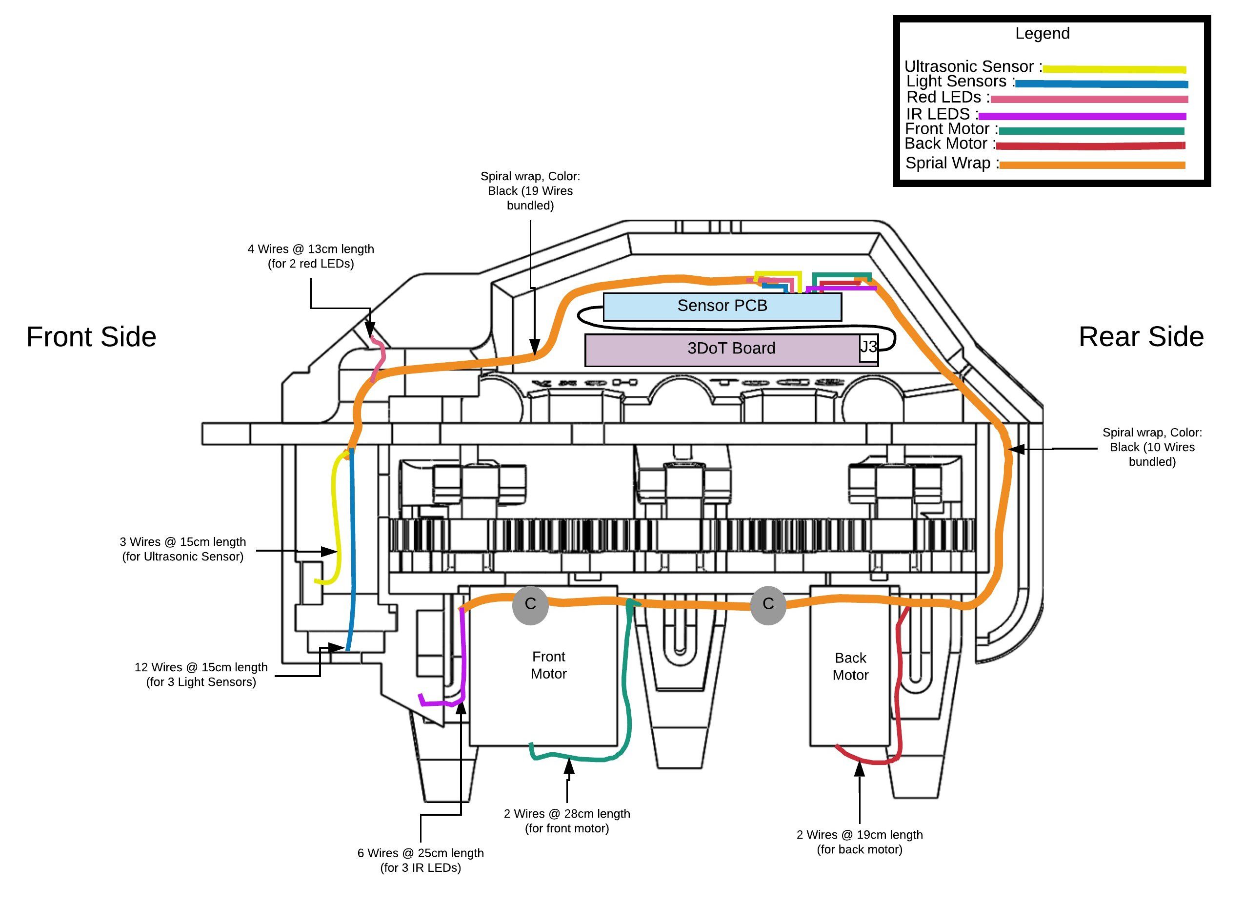
| L2-9 | Micro FOBO wiring shall be nice and clean with the usage of terminal blocks, contact pins, 2.0mm PH series JST connectors, and barrel connectors | Micro FOBO’s wiring contains these type of wires and it is nice and clean. | Inspection | Pass |
| L2-13 | Micro FOBO shall use a 3D printed carbon fiber PLA head chassis and leg components. | Micro FOBO’s head chassis and leg components are 3D printed using the carbon fiber PLA. | Inspection | Pass |
Detailed Success Criteria
In order for this test case to be successful, each of the requirements needs to pass. The goal of this test case will demonstrate that micro FOBO is physically complete beginning from being 3D printed to being built piece by piece. Therefore, the title of this test case goes to explain micro FOBO’s creation, construction, and completion.
Test Environment
This test case will be taking place in the ECS building in room 316. This is where each step of the test case will be presented and show the physically complete micro FOBO.
Assumptions and Preconditions
- 3D printer will function properly and print parts successfully
Procedure Steps
| Step Number | Step Description | Pass Criteria | Recorded Data | Requirement(s) Tested | Test Method |
| 1 | Inspect Jonathon Dowdall’s FOBO and compare it with micro FOBO | Micro FOBO Is a toy robot based on Jonathon Dowdall’s FOBO | L1-4 | Inspection | |
| 2 | Examine micro FOBO and determine and compare with different material used in 3D printed. | Micro FOBO’s parts are 3D printed using the carbon fiber PLA. | L1-7 | Inspection | |
| 3 | Examine the print time of the mini FOBO. The print time document is here. | The total print time should not exceed a time of 7.80 hours | L1-8 | Inspection | |
| 4 | Place a physically completed micro FOBO on the table | The completed micro FOBO is physically ready by May 10 2018. | L1-19 | Inspection | |
| 5 | With none of the wires connected, the assembly of micro FOBO will be demonstrated. Once the it is assembled, micro FOBO will then be disassembled. | The assembly and disassembly for micro FOBO will not exceed the time of 10 mins. | L2-8 | Demonstration | |
| 6 | During assembly, the wires will be inspected and determined whether the correct | The wiring of micro FOBO is nice and clean and uses 2.0mm PH series JST connectors and barrel connectors. | L2-9 | Inspection | |
| 7 | Inspecting the micro FOBO’s head chassis and leg components, it will be determined if the material carbon fiber PLA is used. | Micro FOBO’s head chassis and leg components are 3D printed using carbon fiber PLA | L2-13 | Inspection |
TC-02: Physical Attributes of Micro FOBO
Detailed Description
The Physical Attributes of Micro FOBO test case discusses every components and equipment that the micro FOBO has or utilizes. For example, micro FOBO requires 8 servos in order to stand and to walk. Anything that describes that the micro FOBO needs physically in order to walk through the maze will be in this test case. The goal of this test case is to demonstrate the physical attributes that micro FOBO will need and utilize.
Test Case Traceability and Pass/Fail Matrix
This matrix shall show all requirements that are being tested in this test case. The Pass/Fail Column is populated after the Test Case has been run via the Procedure Steps.
| Requirement Number | Requirement Text | Verification Success Criteria | Verification Method (Test, Analysis, Demonstration, Inspection) | Pass/Fail |
| L1-1 | Micro FOBO will stand on its own without any physical help. | Micro stands on its own without any assistance. | Inspection | Pass |
| L1-2 | Micro FOBO’s electronic components will be easily assembled and disassembled. | Micro FOBO’s electronic components are easily assembled and disassembled | Inspection | Pass |
| L1-3 | Micro FOBO will have 2 legs | Micro FOBO has two legs. | Inspection | Pass |
| L1-6 | Micro FOBO will utilize a 3DoT board or Sparkfun Pro Micro 3.3V/8MHz. | Micro FOBO utilizes a 3DoT board or Sparkfun Pro Micro 3.3V/8MHz | Inspection | Pass |
| L1-10 | Micro FOBO shall be 63% of the overall size of Jonathan Dowdall’s FOBO. | Micro FOBO is smaller than original FOBO by 63% or less
|
Inspection | Pass |
| L1-18 | Micro FOBO will utilize a printable circuit board. | Micro FOBO utilizes a printable circuit board. | Inspection | Pass |
| L2-3 | Micro FOBO will use eight micro servos. | Micro FOBO has eight micro servos | Inspection | Pass |
| L2-4 | Micro FOBO will use UV sensors to detect the colors of the maze. | Micro FOBO UV sensor detects the colors of the maze | Inspection | Pass |
| L2-6 | Micro FOBO shall use a battery that outputs 3.7V | A battery that outputs 3.7V is used. | Inspection | Pass |
| L2-11
|
Micro FOBO shall have indicating LEDs to demonstrate if micro FOBO is on. | Micro FOBO has LEDs and the LEDs turn on. These LEDs indicate whether its making a left or right turn. | Inspection
|
Pass |
| L2-14 | Micro FOBO shall measure 4.5” x 3.25” x 7.25” (l x w x h) | Micro FOBO measures 4.5” x 3.25” x 7.25” (l x w x h) | Demonstration | Pass |
| L2-15 | Micro FOBO shall weigh 460g | Micro FOBO weighs at or near 460 grams. | Inspection | Pass |
Detailed Success Criteria
In order for this test case to be successful, the physical components of the micro FOBO need to present. Each of the requirements of this test case are needed for the micro FOBO to even begin to navigate the maze. Without some of these requirements, micro FOBO would not be able to perform properly. For example, micro FOBO requires two legs and these two legs will help the micro FOBO to be able to stand without any assistance.
Test Environment
This test case will be taking place in the ECS building in room 316.
Assumptions and Preconditions
- The 3D printed parts were printed properly
- Micro FOBO was constructed properly
Procedure Steps
| Step Number | Step Description | Pass Criteria | Recorded Data | Requirement(s) Tested | Test Method |
| 1 | Micro FOBO will be placed on a flat surface. | Once placed on a flat surface, micro FOBO stands without | L1-1 | Inspection | |
| 2 | Micro FOBO assembly is demonstrated. The ease of the assembly and disassembly will be | Micro FOBO is easily assembled and disassembled. | L1-2 | Inspection | |
| 3 | A completed Micro FOBO will placed on a flat surface. | By inspection, micro FOBO has two legs. | L1-3 | Inspection | |
| 4 | Having a 3DOT board and/or Sparkfun Pro Micro 3.3v/8Mhz | A 3DOT board and/or Sparkfun Pro Micro 3.3V/8MHz is present | L1-6 | Inspection | |
| 5 | Place FOBO and micro FOBO side by side and take measurements | Micro FOBO is smaller by 63% less than original FOBO | L1-10 | Inspection/Analysis | |
| 6 | A printable circuit is placed on the table counter. | A printable circuit board is present | L1-18 | Inspection | |
| 7 | A completely built micro FOBO is on the table. The micro servos on the FOBO are to be counted. | Eight micro servos are present in the micro FOBO | L2-3 | Inspection | |
| 8 | A UV sensor is placed on the counter table. | Upon inspecting, there is UV sensor present. | L2-4 | Inspection | |
| 9 | Measure the battery with a voltmeter and determine the volts of the battery. | A battery that outputs 3.7V is present and helps function micro FOBO | L2-6 | Inspection/Analysis | |
| 10 | Inspecting a completed micro FOBO, two LEDs will be on the head chassis. These LEDs will show that the micro FOBO is on. | Two LEDs are on the head chassis turn on indicating that the micro FOBO is on. | L2-11
|
Inspection | |
| 11 | A completed micro FOBO will be measured with a ruler. Measurements will be noted. | Micro FOBO measurements are 4.5” x 3.25” x 7.25” (l x w x h) | L2-14 | Inspection/Analysis | |
| 12 | A completed micro FOBO weight will be measured on a scale. And | Micro FOBO does not exceed a total weight of 460 grams. | L2-15 | Inspection/Analysis |
TC-03: Functionality of Micro FOBO
Detailed Description
The goal of this test case is to demonstrate the functionality of micro FOBO. this is test case describes the creation, construction, and completion of micro FOBO. For each aspect of creation construction, and completion provides certain conditions of how micro FOBO is physically done. It is going from the step of being 3D printed to assembling it together to being completed.
Test Case Traceability and Pass/Fail Matrix
This matrix shall show all requirements that are being tested in this test case. The Pass/Fail Column is populated after the Test Case has been run via the Procedure Steps.
| Requirement Number | Requirement Text | Verification Success Criteria | Verification Method (Test, Analysis, Demonstration, Inspection) | Pass/Fail |
| L1-11 | Micro FOBO shall detect intersections of the maze. | Micro FOBO detects intersections of the maze. | Inspection | Fail |
| L1-12 | Micro FOBO shall be able to perform static walking | Micro FOBO performs static walking | Inspection | Fail |
| L1-13 | Micro FOBO shall produce a 90-degree turn. | Micro FOBO turns at 90-degree turn | Inspection | Fail |
| L1-14 | The user shall guide the Micro FOBO through the maze with the use of the Arxterra application. | The user guides the Micro FOBO through the maze using the Arxterra application | Inspection | Fail |
| L1-15 | Micro FOBO shall record the path of the maze | Micro FOBO records the path of the maze | Inspection | Fail |
| L1-16 | Micro FOBO shall traverse the maze using the recorded path. | Micro FOBO traverses the maze using the recorded path | Inspection | Fail |
| L1-21 | Micro FOBO should be able to perform dynamic walking. | Micro FOBO performs dynamic walking | Inspection | Fail |
| L2-1 | Micro FOBO will be connected via Bluetooth to the app on an android phone | Micro FOBO connects via Bluetooth using an android phone | Inspection | Fail |
| L2-5 | By detecting the colors of the maze, the Micro FOBO shall determine if it is at an intersection. (intersection detection) | Using the colors of the maze, Micro FOBO detects an intersection | Inspection | Fail |
| L2-7 | The user shall use the Arxterra application to move the robot forward, left, and right. | Micro FOBO moves forward, left and right. | Inspection/Analysis
|
Fail |
| L2-12 | Micro FOBO shall record the path of the maze the Micro FOBO traverses on the 3DoT board or the Sparkfun Pro Micro 3.3V/8MHz to navigate the robot through the maze. | Micro FOBO records the path of the maze and navigates micro FOBO through the maze. | Demonstration | Fail |
| L2-16 | Micro FOBO shall detect objects 8 inches from it. | Micro FOBO detects an object 8 inches from it | Inspection | Fail |
| L2-17 | Micro FOBO should be able detect other robots and avoid collision. Micro FOBO should stop completely and wait for command | Micro FOBO detects other robots in the maze and stops. It stops and awaits command. | Demonstration | Fail |
Detailed Success Criteria
The success of this test case will show the functionality of micro FOBO. These functions of micro FOBO will help it traverse the maze. These are different than the ones from test case 4 as in these functions are required to walk the maze. These test cases are what is required for the group project.
Test Environment
This test case will be taking place in ECS 316.
Assumptions and Preconditions
- Previous two test cases are completed.
- The code is running properly.
- Parts are functioning properly.
Procedure Steps
| Step Number | Step Description | Pass Criteria | Recorded Data | Requirement(s) Tested | Test Method |
| 1 | While micro FOBO is walking in the maze, it will use its UV sensor to | Micro FOBO detects an intersection in the maze. | A value is recorded | L1-11 | Demonstration |
| 2 | A functional micro FOBO will be placed on the table counter. The code for micro FOBO will be | Micro FOBO is able to static walk | L1-12 | Demonstration | |
| 3 | While the micro FOBO is running, the micro FOBO will attempt to turn. | A 90-degree turn is produced while it is attempting to turn. | L1-13 | Demonstration | |
| 4 | While the user is connected to the micro FOBO, the user should be able to guide micro FOBO through the maze. | The user is able to guide micro through the maze. | L1-14 | Demonstration | |
| 5 | While traversing the maze, micro FOBO records the maze. | Micro FOBO records the path of the maze it took. | L1-15 | Demonstration | |
| 6 | Using the recorded path of the maze, micro FOBO will traverse this path | Micro FOBO traverses the record path. | L1-16 | Demonstration | |
| 7 | While micro FOBO is walking, a dynamic can be inspected. | Micro FOBO dynamic walks. | L1-21 | Demonstration | |
| 8 | Using the Arxterra application, micro FOBO will be connected via Bluetooth. | Micro FOBO is connected via Bluetooth | L2-1 | Demonstration | |
| 9 | Micro FOBO will be on the maze, walking. While walking, micro FOBO will detect the colors of the lines. And it will determine whether if its at an intersection | While on the maze, micro FOBO detects the colors on the maze. Based on the colors of the maze, it will determine if it is at an intersection. | L2-5 | Demonstration | |
| 10 | Once micro FOBO is connected to the Arxterra app, the user will demonstrate the functions of walking forward, turning left and right. | The user is able to make micro FOBO walk forward, turn left and right. | L2-7 | Demonstration | |
| 11 | Micro FOBO will record the path it takes on the 3DOT board or the Sparkfun Pro Micro 3.3V/8MHz to navigate the robot through the maze. | Micro FOBO records the path of the maze on the 3DOT board or the Sparkfun Pro Micro 3.3V/8MHz and navigates it throught the maze. | L2-12 | Demonstration | |
| 12 | Micro FOBO will be placed on the table. The program for micro FOBO will be running and the ultra sonic sensor will detect objects 8 inches away. | Micro FOBO detects objects 8 inches from it. | L2-16 | Demonstration | |
| 13 | While in the maze, micro FOBO will detect other robots on the maze and avoids collision. It will stop and await command. | Micro FOBO detects other robots in the maze and stops to avoid collision. It then stops and awaits command. | L2-17 | Demonstration |
TC-04: Micro FOBO’s Extra Functionality and Challenges
Detailed Description
This test case will demonstrate any extra functionality and challenges for micro FOBO. The requirements for this test case are should and shalls for micro FOBO. These extra things that are not required for the basic functionality of micro FOBO but the extra features and challenges that we wanted to demonstrate for micro FOBO. These extra functionalities include playing a musical tune and/or taking a bow at the end of maze. These are extra functions to demonstrate some creativity that micro FOBO can perform.
Test Case Traceability and Pass/Fail Matrix
This matrix shall show all requirements that are being tested in this test case. The Pass/Fail Column is populated after the Test Case has been run via the Procedure Steps.
| Requirement Number | Requirement Text | Verification Success Criteria | Verification Method (Test, Analysis, Demonstration, Inspection) | Pass/Fail |
| L1-17 | Micro FOBO shall traverse cloth, paper, and linoleum. | Micro FOBO walks on cloth, paper, and linoleum. | Inspection | Fail |
| L1-20 | Micro FOBO should step over a square rod 1cm tall by 1cm wide by 10 cm long | Micro FOBO steps over a square rod of 1cm tall by 1cm wide by 10cm long. | Inspection | Fail |
| L2-10 | Micro FOBO shall play a musical tune when the maze is completed | Micro FOBO plays a musical tun when the maze is completed. | Inspection | Fail |
| L2-18 | Micro FOBO should take a bow at the end of the maze. | Micro FOBO takes a bow at the end of the maze. | Inspection | Fail |
Detailed Success Criteria
This test is successful if micro FOBO performs any of the extra functions or challenges. These requirements were to demonstrate some creativity of micro FOBO.
Test Environment
This test case will be taking place in ECS 316.
Assumptions and Preconditions
- Micro FOBO test case 1 through 4 functions properly.
Procedure Steps
| Step Number | Step Description | Pass Criteria | Recorded Data | Requirement(s) Tested | Test Method |
| 1 | Micro FOBO will placed in different terrain fields such as cloth, paper and linoleum and it will walk on those terrain fields | Micro FOBO is able to traverse cloth, paper, and linoleum. | L1-17 | Demonstration | |
| 2 | The square rod measuring 1cm tall by 1cm wide by 10cm long is placed on the table. Micro FOBO will walk toward the square rod | Micro FOBO steps over a square rod mearsuring 1cm tall by 1cm wide by 10cm long. | L1-20 | Demonstration | |
| 3 | Micro FOBO traverses a path of the maze. It will finish the maze. | Once micro FOBO completes the maze, a musical tune plays to show that it finished maze. | L2-10 | Demonstration | |
| 4 | Micro FOBO traverses a path of the maze and it will finish the maze. | After the musical tune that is played when the micro FOBO finished the maze, micro FOBO takes a bow. | L2-18 | Demonstration |
TC-05: Cost, Storage, Fitting in Maze Dimensions
Detailed Description
This test case describes the cost, the storage and the fitting in the maze for micro FOBO.
Test Case Traceability and Pass/Fail Matrix
This matrix shall show all requirements that are being tested in this test case. The Pass/Fail Column is populated after the Test Case has been run via the Procedure Steps.
| Requirement Number | Requirement Text | Verification Success Criteria | Verification Method (Test, Analysis, Demonstration, Inspection) | Pass/Fail |
| L1-5 | Micro FOBO will fit within the classroom cabinets. 28”x13”x14.5” | Micro FOBO fits in the cabinet within those dimensions | Inspection | Pass |
| L1-9 | Micro FOBO shall not exceed a cost of $250.00 to construct. | Cost does not exceed $250.00 | Inspection | Pass |
| L2-2 | Micro FOBO dimensions of robot will need to be small enough to fit in a 4in by 4in box for maze purposes. | Micro FOBO fits in the 4in by 4in square of the maze. | Inspection | Pass |
Detailed Success Criteria
This test case is successful if micro FOBO does not invalidate any of the requirements. Micro FOBO meets each of the requirements.
Test Environment
This test case will be taking place in ECS 316.
Assumptions and Preconditions
- Micro FOBO is successfully built.
Procedure Steps
| Step Number | Step Description | Pass Criteria | Recorded Data | Requirement(s) Tested | Test Method |
| 1 | Carry micro FOBO to the cabinets and place it in one of the cabinets. | Micro FOBO fits in the cabinet within those dimensions | L1-5 | Demonstration | |
| 2 | View the cost report for micro FOBO and review the total cost. | Micro FOBO’s cost does not exceed $250.00 | L1-9 | Inspection/Analysis. | |
| 3 | Micro FOBO will be placed in one of maze squares. | Micro fits inside of the 4in by 4in maze squares. | L2-2 | Inspection/Demonstration |
Appendices
This section will contain any additional documentation needed to verify/validate requirements. For example, if a project has a cost constraint requirement, include the cost breakdown spreadsheet below as a subsection and reference the appendix subsection in the related Test Step in the Test Procedure. If another group needs to verify something by hand via calculation, include the calculations as a subsection below and reference the appendix subsection in the related Test Step in the Test Procedure.