Spring 2018 3DoT Hexy: Preliminary Design Review
By: Eduardo De La Cruz (Project Manager & Manufacturing), Raymundo Lopez-Santiago(Mission, Systems, Test), Kris Osuna (Electronics & Controls)
Verified by: Eduardo De La Cruz (Project Manager & Manufacturing Engineer)
Approved by: Miguel Garcia (Quality Assurance)
Table of Contents
Mission Objective
- Design and fabricate a remote controlled, competitively priced, toy robot that is capable of memorizing and traversing a path.
- The child “teaches” his/her robot by guiding it through a maze. Once the child and robot team solve the maze. The child returns the robot to the entrance of the maze and quizzes the robot to see if it has learned the maze.
- Additional robots may be introduced into the maze while the robot is moving through the maze. The robot should avoid collisions with the other robots.
- Parents and friends may remotely view the progress of their child’s robot.
- Our game testers will be given the robots on the day of the final. The test room is ECS 316. The maze will be located in the front of the room (about 8 ft x 18 ft).
Level 1 & Level 2 Requirements
By: Raymundo Lopez-Santiago
Requirements follow the following numbering conventions:
C-xx is used for all common requirements for all projects under The Robot Company.
L1:xx is used for all Level 1 requirements specific to 3DoT Hexy.
L2:xx is used for all Level 2 System and Subsystem requirements specific to 3DoT Hexy.
3DoT Hexy requirements will be updated as the project is further completed.
Level 1 Requirements
Program Requirements
C-01:
In accordance with the Spring 2018 final schedule, the project shall be completed by May 8th, 2018 and shall be prepared for a demonstration on the linoleum floor of ECS 316 on May 15th between the hours of 10:15 am – 12:15 pm.
C-02:
Documentation for the project shall be completed a week prior to the day of demonstration (May 8, 2018).
C-03:
The robot will be designed to be a toy for people ages 8+.
C-04:
In order to minimize manufacturing cost, and packaging cost the robot shall be able to be constructed from subassemblies within 10 minutes.
C-05:
The robot will be remotely controlled wirelessly via bluetooth using the ArxRobot Android or iPhone application.
C-06:
The robot will need to navigate remotely through a custom-built maze (built by AoSa image), memorize the path it took, start over, and autonomously travel through the path it took.
C-07:
Video support during autonomous navigation will be provided via the Arxterra control panel, as well as a live VR feed.
C-08:
The robot shall avoid collisions if it encounters other robots while navigating through the maze. This involves detecting the robot, retracing steps back, and moving to a room that allows the other robot to have a safe passage.
C-09:
For quick production of the prototype, the preliminary project shall be restricted to six hours of total printing time with a 2 hours limit for each single print.
C-10:
The robot shall use a v6.16 3DoT board.
C-11:
The robot shall demonstrate the capabilities of the 3DoT micro-controller for DIY hobbyists.
C-12:
The robot shall be designed in such a way that there are no dangling or exposed wires and the final fabrication is pleasing to the customer.
C-13:
The robot shall incorporate 3D printed parts to demonstrate the feasibility of the 3DoT board for 3D printed robots.
Project Requirements
L1-1:
The robot shall use sensors to: detect robots disrupting their path, for intersection detection, and for either line following or hedge following.
L1-2:
The robot shall use the same maze to compete in a game of who gets out first. (Defined by both 400-D sections)
L1-3:
To keep cost down, and keep as a toy aspect, the robot shall use only 2 micro motors to drive the movement of the robot.
L1-4:
Spiderbot shall have an allocated budget of $250, however to compete with the existing robot toy market we shall try to minimize the cost of production as much as possible.
L1-5
Spiderbot shall have custom SMD I2C shield as platform to build from and will incorporate peripherals for sensors and motors.
L1-6:
Spiderbot’s dimension shall have a chassis large enough to house a 3×7 cm 3DoT board.
Level 2 Requirements
System Requirements
L2-1:
Communication to the robot will be through the HM-11 bluetooth module.
L2-2:
The robot shall use a single RCR123A 3.7 V, 650mA rechargeable Li-ion battery to power the 3DoT board, which will power the drivetrain and all attached peripherals.
L2-3:
The robot shall use 3 UV sensors connected to a custom PCB.
L2-4:
The robot shall use a HC-SR04 ultrasonic sensor to handle robot avoidance.
L2-5:
The robot shall use 3D printed chassis and legs. This follows from the project level requirement about using 3D printed parts.
L2-6:
The robot will use a cam system identical to that of 3DoT David to drive the movement of the legs while navigating through the maze.
L2-7:
The robot shall use 2 micro guard motors to drive the motion of the robot.
L2-8:
The robot shall use one RGB color sensors to handle intersection detection.
L2:9
The robot shall incorporate 6 legs in the design of the drivetrain to improve stability while moving, to support its own weight and to mimic the behavior of a spider.
L2-10
The Arxterra control panel shall display the current battery level, as well as all sensor data.
Sub-System Requirements
L2-4a:
Ultrasonic sensor shall have a range of 0.5-meter radius to detect and respond accordingly to other robots.
L2-5a:
The robot shall use PLA or ABS filament in the fabrication of the chassis and legs. This will minimize the mass of the robot, while at the same time being strong enough to hold its weight.
L2-6a:
Gears shall have a gear capture system to prevent them from popping (main issue encountered in 3DoT David design). This ensures the cam system will work without fear of popping gears.
L2-9a:
The robot shall operate in a tripod form, having three legs (2 outer in one side and middle leg in the other side) to provide stability while moving.
Resources:
- https://www.arxterra.com/spring-2016-3dot-spider-bot-preliminary-research-project/
- https://docs.google.com/document/d/1kwObe9HkGBeCjMYAETA5GiChyxhY1o6bpcmhWKbNFv8/edit
- https://www.arxterra.com/spring-2016-3dot-david-executive-summary/
- https://www.arxterra.com/2016-spring-3dot-david-final-project-blog-post/
System Block Diagram
By: Raymundo Lopez-Santiago
The system block diagram mimics the interface matrix developed for 3DoT Hexy. The 3DoT Hexy system block diagram below shows the different parts of the robot and how they interact with each other. A total of 9 pins out of the 16 pins available from the 3DoT board will be used for the custom PCB’s. The two custom PCB’s will be designed and built to add an I2C expander which will connect to all sensors, also a boost converter to provide 5V to the motor driver. 3DoT Hexy will be powered from a single 3.6V RCR123A battery. Communication for mobile operation of 3DoT Hexy will be done using the HM-11 bluetooth module. Any changes will be added as needed.
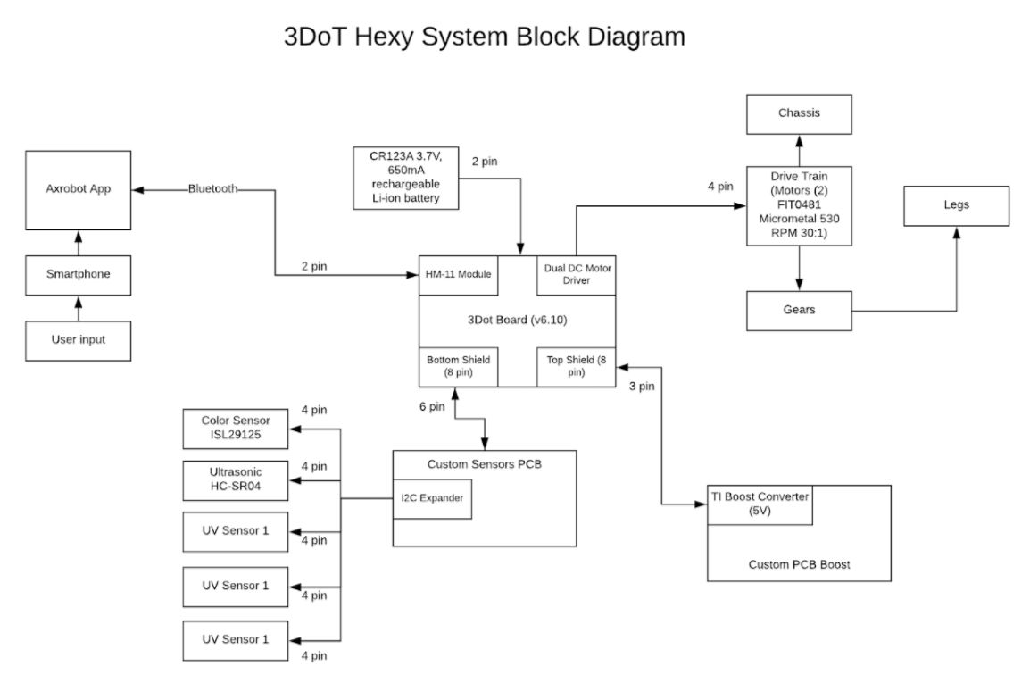 Figure 1: System Block Diagram
Work Breakdown Structure
By Eduardo De La Cruz
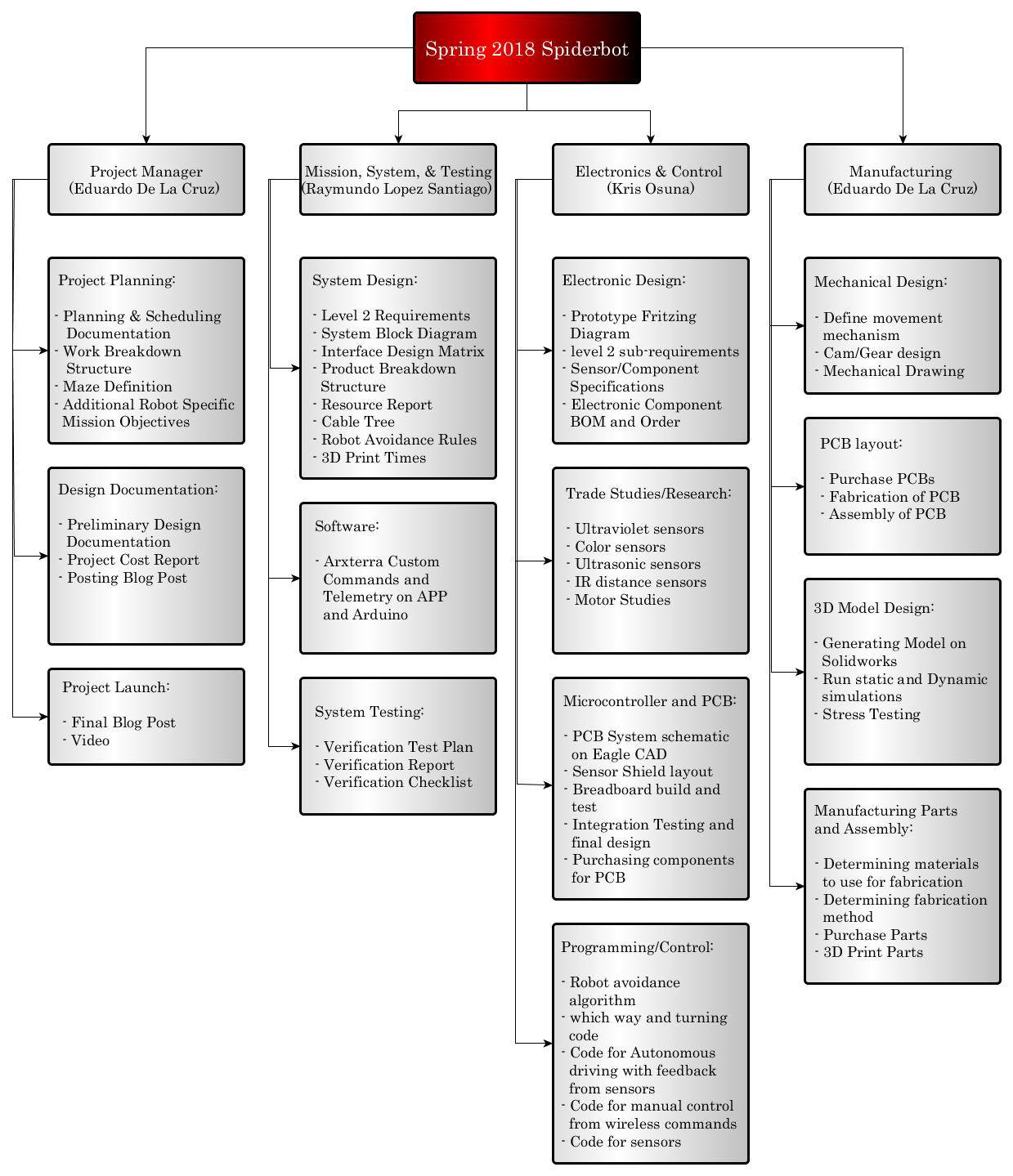 Figure 2: Work Break Down Structure, generated using yEd Graph Editor
Product Breakdown Structure
By: Raymundo Lopez-Santiago
The product breakdown structure outlines the major systems of the robot. The 3DoT Hexy Product Breakdown Structure (PBS) below shows the different components (subsystems) of each part of the overall robot. 3DoT Hexy is split into five sections (Movement, Software, Sensors, Chassis, Power) for the PBS. Anything related to the movement system which includes motors, joints, gears, and legs are the main parts for mobility of 3DoT Hexy. Communication via Bluetooth from a smartphone and the Arxterra app allow for wireless control of 3DoT Hexy. Sensors such as the color and UV sensors will aid in detecting corners and for the case of the ultrasonic sensor, it will aid in detecting robots. The chassis will be 3D printed in either PLA/ABS plastic. 3DoT Hexy and its peripherals will be powered by a single 3.6V RCR123A battery. Any changes will be added as needed.
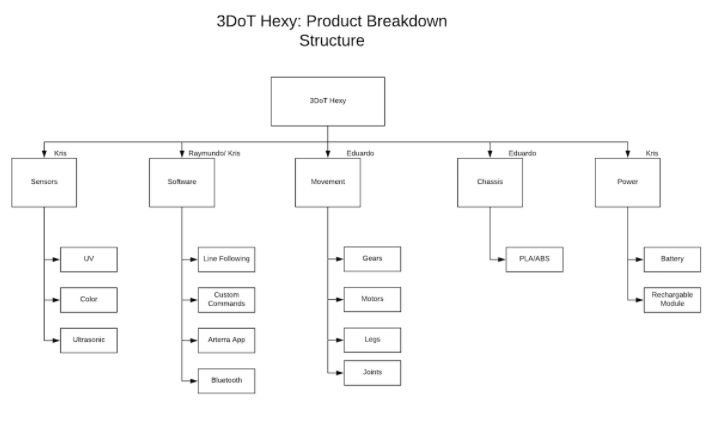
Figure 3: Product Break Down Structure
Interface Matrix
By: Raymundo Lopez-Santiago
Three separate interface matrices are created in a table format to show how the available pins for specific systems are going to be allocated in the design. This document helps show how things should be connected together using the corresponding pin names that are provided from the data sheets. For this project, we break up systems into 3 interface matrices which are the 3DoT interface, the Custom Sensor PCB and the Custom Boost PCB. The 3DoT interface matrix shows the pins allocated from the 3DoT board and how they connect to the two custom PCB’s. The Custom sensor PCB interface matrix shows connections used to connect the I2C expander (TCA9548A), Ultrasonic sensor (HC-SR04), and UV sensors (Si1145) to the 3DoT board interface. The Custom Boost PCB interface matrix shows connections used to connect the Boost converter ( TPS61253AYFFT) to the 3DoT board Interface. Since project Biped will be using similar PCB designs, we have decided to split the work and have our team work on the Custom Boost PCB design while the Biped team will work on the Custom Sensor PCB design.
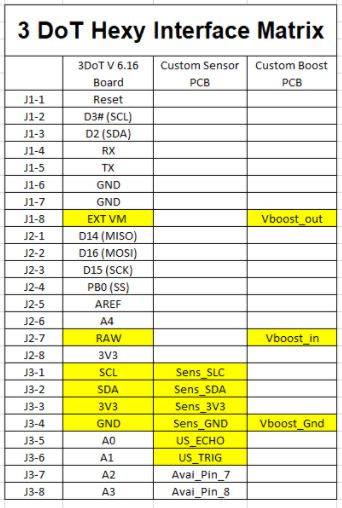
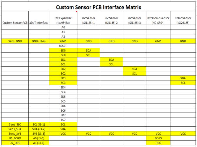
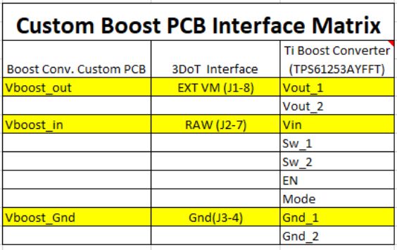
Figure 4: Interface Matrix
Fritzing Diagram
By Kris Osuna
We will have three UV sensors. One sensor follows the line when another sensor is triggered 3DoT Hexy will know that the course has been disrupted and needs to readjust. We are using three UV sensors which requires three separate SDA/SCL pins, because of this we have an I2C expander. We will have two UV LEDs illuminating the front of 3DoT Hexy so the UV marker is detected. We use the ultrasonic sensor to find if other devices are in the way and if 3DoT Hexy needs to react. A dual motor drive is needed to drive both sides of 3DoT Hexy.
Please Note:
UV sensor = Adafruit Si1145 Breakout Board – Uv Index/IR/Visible Sensor
UV LEDs = UltraViolet LED Lamp
Ultrasonic Sensor = HC-SR04
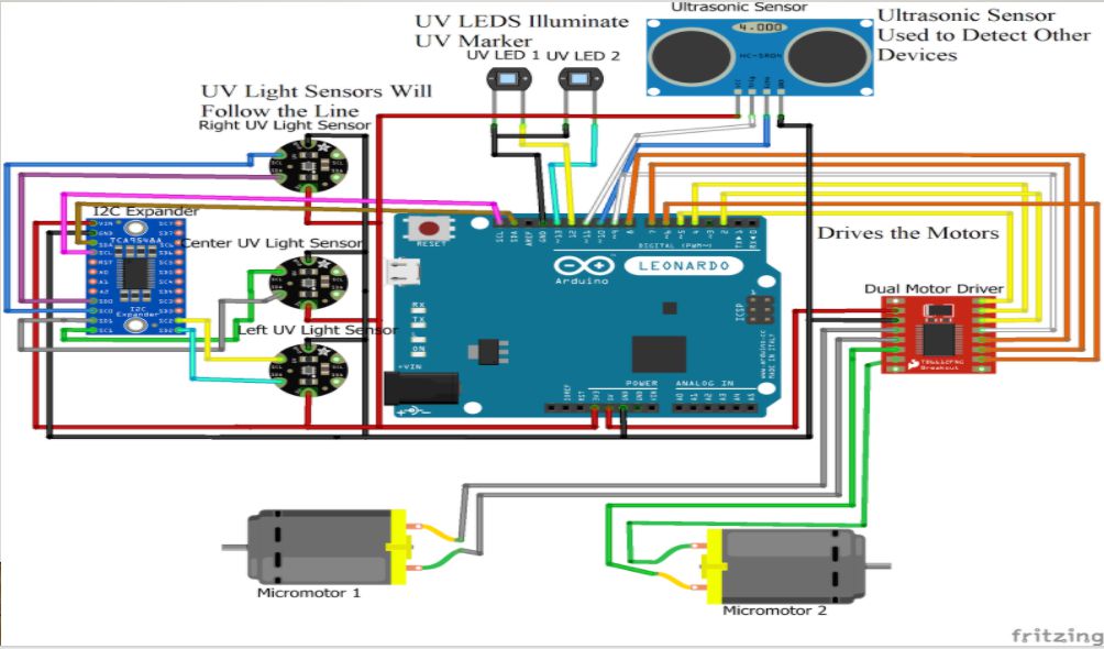
Figure 5: Fritzing Diagram
Mechanical Drawings
By: Eduardo De La Cruz
Having had decided to go with a cam system design similar to that of Spring 2016’s 3DoT David, we decided to get in contact with the owner of 3DoT David, and ask for permission to borrow the model for use as a reference, we went on to solve design flaws in 3DoT David’s mechanical design, came up with solutions, and rendered our own design fixing these bugs. Below are mechanical sketches of our design followed by brief explanations of why things look the way they are. If interested in more detailed explanation for design changes made based on the 3DoT David model, please read the blog post “Spring 2018 3DoT Hexy: Improving 3DoT David Design”. If interested in more details about how the mechanism works please see “Spring 2018 3DoT Hexy: Decision on Movement Mechanism”, and “Spring 2018 3DoT Hexy: Determining Gear Design” .
3DoT Hexy Mk-1:
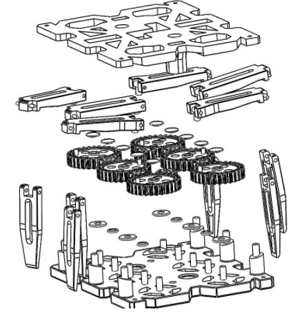 Figure 6: Exploded View of 3DoT Hexy Mk-01
An exploded view of our spider can be seen above. In all, we will have: 6 legs, 6 femurs, top and bottom plate, washers, x6 30T gears, x8 10T gears, and gear caps (to prevent popping).
Below are sketches of our design modeled using solidworks. All measurements are in mm.
Bottom Panel:
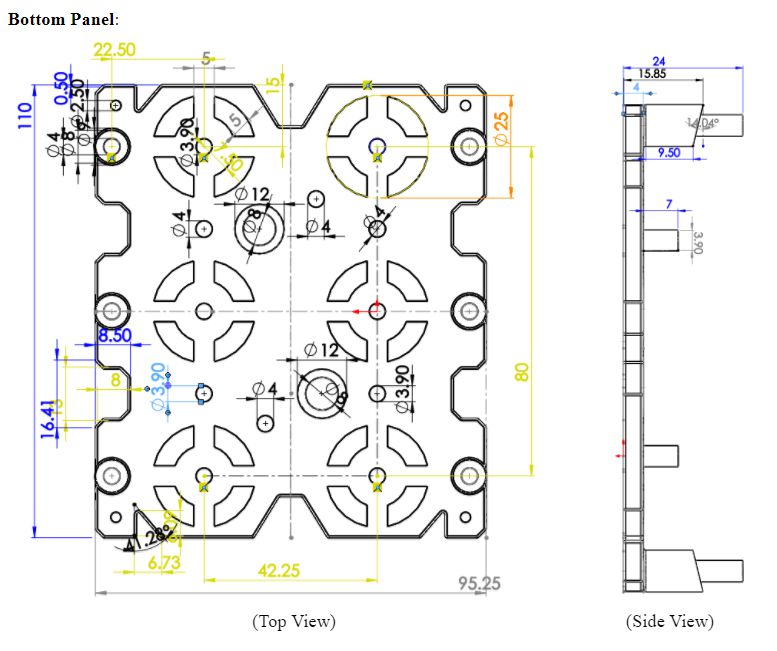 Figure 7: Bottom Panel Dimensions
For the bottom panel, femur lifting guides will be integrated into the chassis instead of having them stick out like in 3DoT David’s design. This is done to reduce the overall width of the robot. Ten shafts with 4mm diameter will be located at 21.125mm from the center axis. We will extrude cut patterns to reduce 3D print times while at the same time giving our design a unique and appealing view to distinguish it from 3DoT David. The guides for the femurs will be angled. This is done in order to provide a smooth transition from ground to peak heights during the legs extension. For the holes found along the center axis: big holes will be used to run wires from top to bottom panel, and smaller holes will be used for driving motor connections. The design will have more holes upon determination of the position of the custom PCB board, battery, and 3DoT board.
Top Plate:
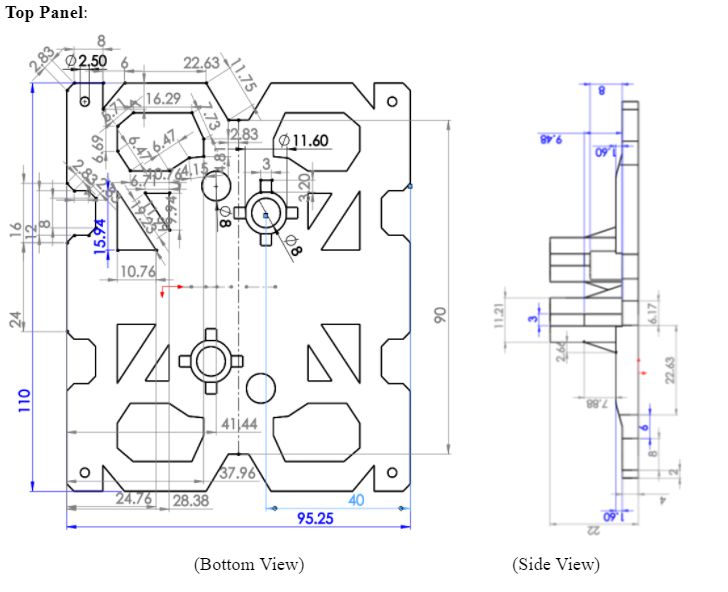 Figure 8: Top Panel Dimensions
Top view will be flat and showing only the extrusions. The circles along the center axis will be: small holes, gear captures to keep the driving gears from popping and bigger hole will be a round tube extruding from top panel and that will connect to the bottom panel. Providing an isolated passage for wires from top panel to bottom panel without obstructing cam system. We will extrude cut patterns to reduce 3D print times while at the same time giving our design a unique and appealing view to distinguish it from 3DoT David. The design will have more holes upon determination of the position of the custom PCB board, battery, and 3DoT board.
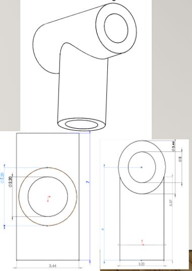
Femurs:
Femurs will be re-designed based on 3DoT David’s design review to incorporate more contact points for femur and tibia joint. Like 3DoT David, the back, middle, and front femurs will have a unique design. The reason for doing this is to provide clearance for when we put the screw mounts in each corner.
The three type of femurs:
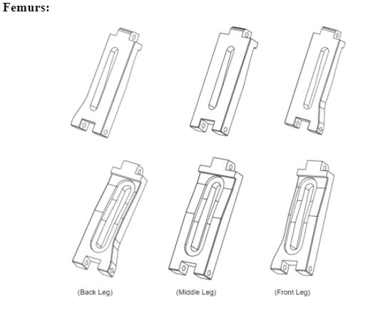 Figure 9: Three Types of femurs
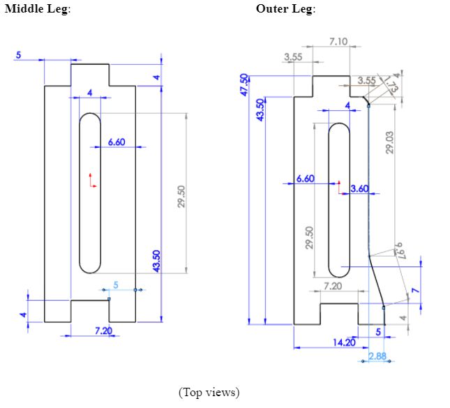 Figure 10: Middle femur dimensions
Note: The back leg will have the same measurements with extrude-cut on opposite side.
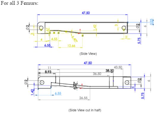 Figure 11: Femur Dimensions
We decided that integrating the lift mechanism into the femurs of the legs would give us more control over the lift angle (since it will be based on the angle of the contour we define), as well as reduces the width of the robot since we will eliminate the need of the protruding lift mechanism. As an added extra, we also expect to see reduced 3D print times for the femurs.
Our solution involves re-designing the femurs and the base to have a guide that will increment the angle of the femur as the femur rotates outward, providing lift. How it works:
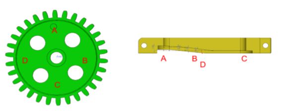 Figure 12: Relation between femur and gear during gear rotation
At point A the femur should be touching the floor and preparing for thrust. At point B, the femur begins ascending. At point C the femur is at its peak lift. At point D, femur is descending.This solution enables us to control the lift of the legs based on the angles of the femurs; eliminating the need of the protruding mechanism from 3DoT David. The guide that the femurs will follow will also have an angle to provide a smooth transition from point A to point C. More details of how this works can be found in “Spring 2018 3DoT Hexy: Improving 3DoT David Design”.
Tibias:
The tibias will have a new joint redesign in order to increase femur-to-tibia contacts for joint strength. Previous design only had a single contact point and was susceptible to loosening.
New design will have 5 contact points.
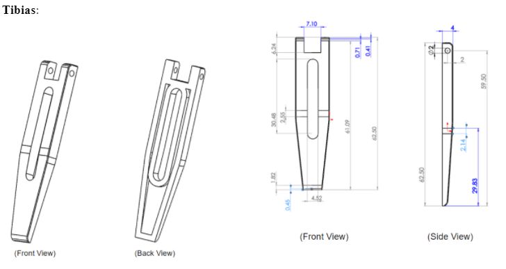 Figure 13: Tibia Dimensions
The legs will be wider than those of 3DoT David due to the increase width needed to increase contact point of femur-to-tibia joint. The result we can expect from this is increased 3D print times due to larger surface area of tibias. To try to fix this issue we trimmed the width of the tibias by 2mm (from 6mm to 4mm) and decided to shell/hollow out the tibias and cut out excess material by making the opening right down the middle. The legs have a 2mm holes that will align with the 2mm hole of the femur. Thread will be created through this joint and a screw will be placed through femur-to-tibia joint to prevent them from moving.
Additional Components we will use in our design will be:
- Washers with 4 mm bore
- Gear caps (to prevent popping)
- Joints for gears to femurs
3D Model: 3DoT Hexy Mk-1
By Eduardo De La Cruz
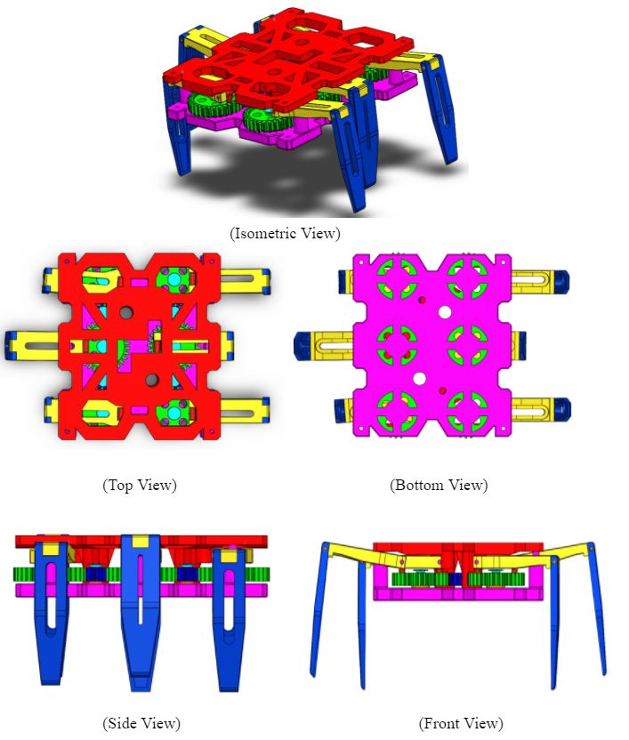 Figure 14: 3D Assembly of 3DoT Hexy Mk-01
3D Simulation
By Eduardo De La Cruz
Resources
Resource Reports (Power, Mass, Cost)
By Raymundo Lopez-Santiago
This section provides all of the information for the three major resources that are being tracked which are Power, Mass, and Cost. Values obtained for 3DoT Hexy are estimates based on previous research. At this moment, not all measurements/testing for all sensors are finished. For the Battery and 3DoT values (mass, power) were estimated based on the final blog post of 3DoT David. For the 3DoT Hexy design, we are building of the design of 3DoT David and further making improvements. After testing several weight values on top on 3DoT David, we determined the total project allocation mass for 3DoT Hexy should be 500g to still be able to move. For the project power allocation, it was determined to be 1.1A from the 3.6V RCR123A battery. Values will be updated as project is progressed.
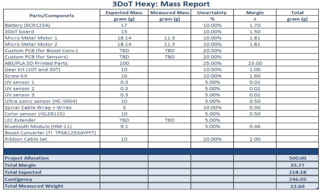 Table 1: Mass Report
 Table 2: Cost Report
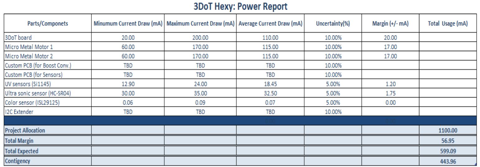 Table 3: Power Report
Resources:
- https://www.sparkfun.com/products/14451
- https://www.parallax.com/product/28015
- https://www.digikey.com/product-detail/en/dfrobot/FIT0481/1738-1261-ND/7087158
- https://www.sparkfun.com/products/12829
- https://www.adafruit.com/product/1981
- https://www.arxterra.com/2016-spring-3dot-david-final-project-blog-post/
- https://www.frys.com/product/5016445?source=google&gclid=Cj0KCQiA2snUBRDfARIsAIGfpqGw6ov6eExenZ0MzyByUMZLA4PL2T_D5V22oT1b9NsDdywbOCx8tOcaAuw_EALw_wcB
- https://www.amazon.com/gp/product/B00V66YJQI/ref=ox_sc_act_title_1?smid=A2KD6YPQW2NHJU&psc=1
Planning & Schedule
By Eduardo De La Cruz
The schedule we will use will practically mirror the the time frames and due dates priorly established in the task matrix. The goal is to provide a visual reference of how far or close one is from reaching their deadlines for a given task.
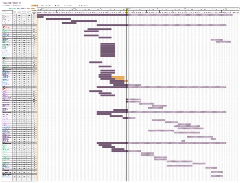 Figure 15: Project Planner generated using EXCEL Project Planner
Dark purple represents our progress, light purple represents what needs to be done. If we exceed the due date the bar will turn orange. Orange lets us know how many days it was late after the due date due to time extension request. Task for each division are color coded and their is a legend at the top explaining each color.
Note: Division members may take on task from other divisions if they see that they have the time available in their existing schedules to aid other divisions in getting their task done.
A link to our task matrix and project schedule generated can be found below:
Resource:
https://docs.google.com/document/d/17JkOMh4iSVdERfUkY3p-8k-tiUVcahm0qcVtd_GDAcg/edit
Project Burndown
By: Eduardo De La Cruz
The graph shows how task will be distributed over the course of the semester. The goal is to finish all task before execution of the mission.
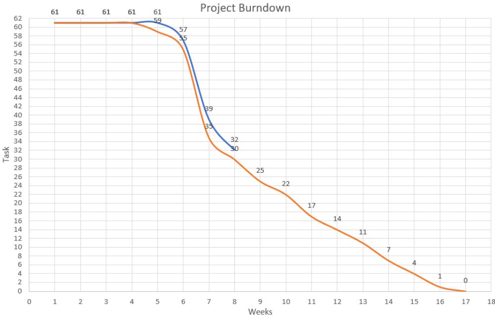
Figure 16: Project Burndown
Blue = Current Progress, Orange = Desired Progress
As off week 8, we have completed about half of the task defined in the task matrix. So far, we have submitted most if not all preliminary task documentations, and a few trade studies done by each division engineer showing their progress. For more details on what is due each week based on the above burndown read, “Spring 2018 3DoT Hexy: Project Planning and Scheduling”.
Summary of experiments done/Rapid Prototyping Completed
UV Testing
By Kris Osuna
Power Point Presentation
By: Eduardo De La Cruz (Project Manager)
UPDATED-3DoT Hexy_ Preliminary Design Review (1)