Spring 2018 3DoT Hexy: Assembly (Prototype/Final)

By: Eduardo De La Cruz (Project Manager & Manufacturing Engineer)

Approved by: Miguel Garcia (Quality Assurance)

Table of Contents

Introduction

The purpose of this blog post is to demonstrate how all parts designed in Solidworks were put together along with other outsourced materials. We will be assembling two  models of our robot: the prototype which is based of our preliminary design review design and our final design which can be found in “Spring 2018 3DoT Hexy: 3D Model”.   

Related Requirements

C-03:

The robot will be designed to be a toy for people ages 8+.

C-04:

In order to minimize manufacturing cost, and packaging cost the robot shall be able to be constructed from sub assemblies within 10 minutes.

Assembly of Final Model – (May 07, 2018)

Parts

3D Printed Parts:

  • x1 – Sensor Enclosure
  • x1 – Hardware Enclosure
  • x1 – Top plate
  • x1 – Bottom plate
  • x1 – Cable tube
  • x2 – Left Femurs
  • x2 – Right Femurs
  • x2 – Middle Femurs
  • x6 – Tibias
  • x6 – Femur-to-gear


Components Outsourced:

  • x22 – 3 -.5 mm nylon lock nuts
  •  x6 – 3 -.5 mm hex nuts
  • x10 – 3 -.5 mm x 16 mm flat head machine screws
  • x12 – 3 -.5 mm x 20mm Socket cap screws
  • x6 – 3 -.5 mm x 16mm Socket cap screws
  • x12 – 8 mm x 4 mm OD x 3 mm ID aluminum bushings  
  • x10 – 3 mm ID brass plated bushings
  • x16 – 3mm x 6mm (ID/OD) (#4) washers
  • x10 – 3mm x 8mm (ID/OD) (#6) washers
  •  x4 – 3 -.5 mm x 45 mm socket cap screws
  •  x4 – 1’ x ¼ ‘’ OD nylon spacers
  •  x2 – Actobotics micro gear motor enclosure
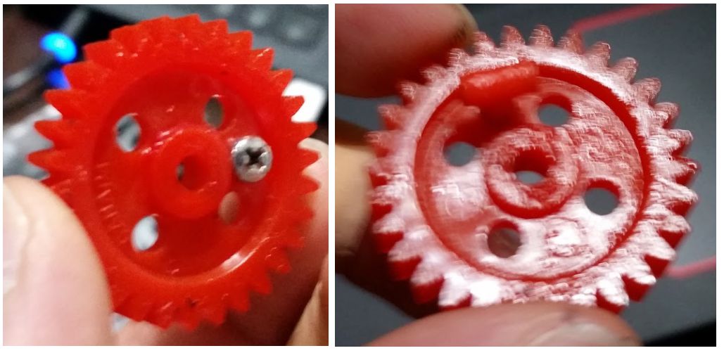
  •  x6 – 30T Ajax Scientific plastic gears
  •  x4 – 10T Ajax Scientific plastic gears
  •  x2 – Driving gears
  •  x2 – 530 RPM micro gear motors
  • x10 – VxB 3 x 6 x 2.5 mm bearings


Required tools:

  • Philip Screw Driver
  • 3 mm hex nut driver
  • 3 mm allen key


Steps 

Note: The leg assembly, which is the tibia, femur and gear will be advertised as a single piece to reduce assembly and disassembly times. However, for the purpose of this blog post we will go through the leg assembly for reference purposes.


Leg Assembly

Step 1: Connect the tibia to the femur and fasten them using a 20 mm socket cap screw and a hex nut.


Step 2: Connect the femur-to-gear joint to the gear and fasten them together by running a 16 mm socket cap screw with a #4 washer through the bottom of the gear and fasten them together using a lock nut.


Step 3: Connect the other end of the femur to the gear-to-femur joint using a 20 mm socket cap screw and a lock nut.


Step 4: Adjust how tight each screw is to achieve the best movement


Final Assembly


Step 1: Run a 16 mm flat head machine screw through the bearing bore of the gear, add a brass bushing and a washer through the other end of the screw, and fasten this assembly to the chassis using a lock nut and #6 washers.


Step 2: Connect the legs to the chassis leg guides


Step 3: Connect the top plate to the bottom plate using 45 mm socket cap screws, 1 inch spacers, and lock nuts.


Step 4: Connect the sensor enclosure to the chassis by using the same 45mm socket cap  screws to one end of the chassis.


Step 5: Attach the motor enclosure to the bottom plate.


Step 6: Attach the cable tube to the back using the custom mount fabricated and using a 3 mm screw.


Step 7: Place the hardware cover which should clip on by the use of magnets.


For instructions on installing the hardware, reference the system integration and testing post.
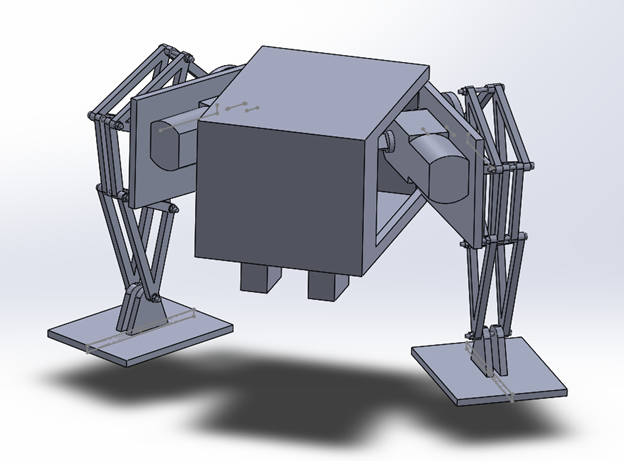
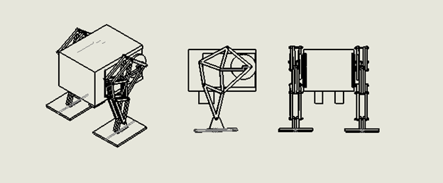
 

Final Assembly   

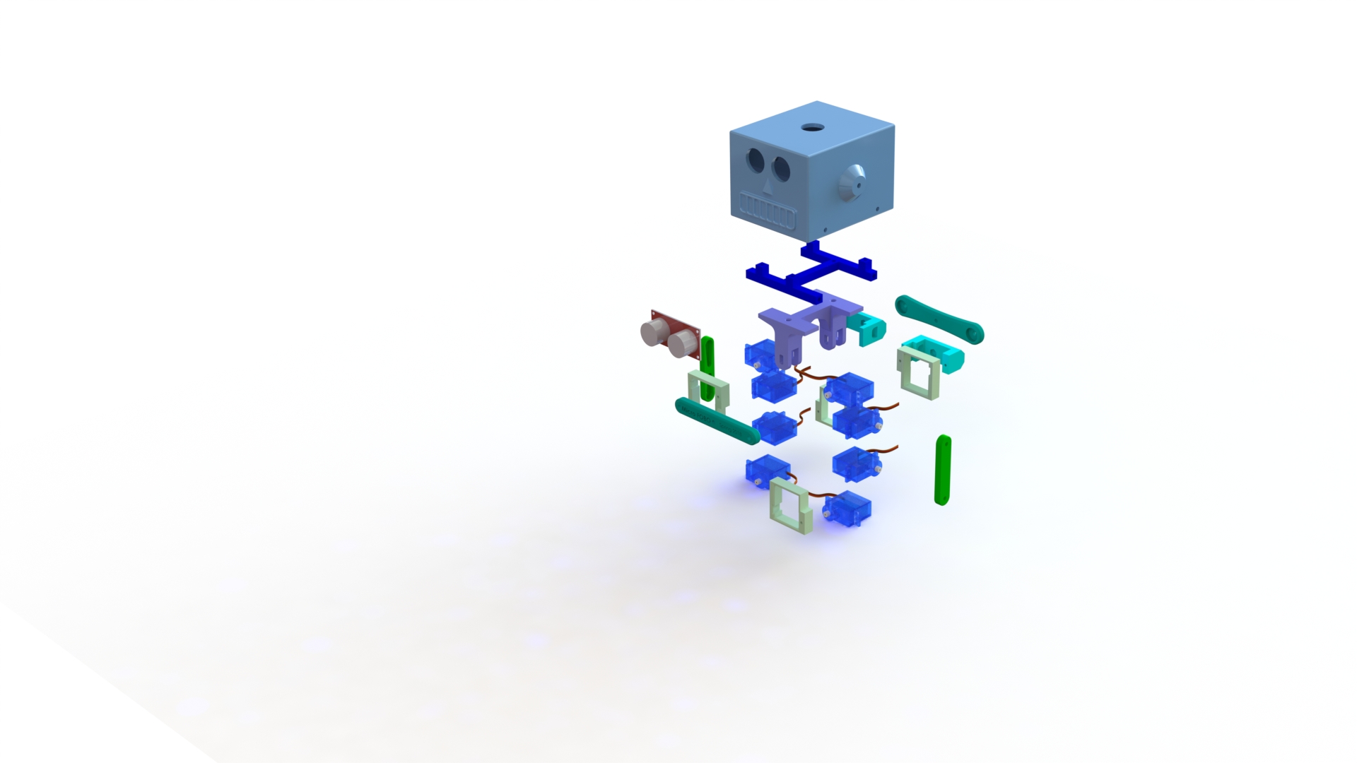
Assembly of Hexy Mk-01 (Prototype) – (April 3, 2018)

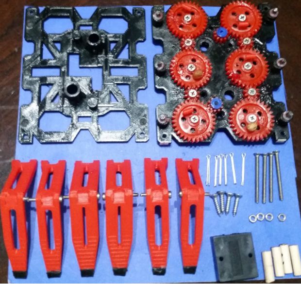
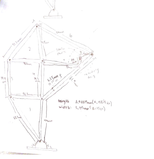
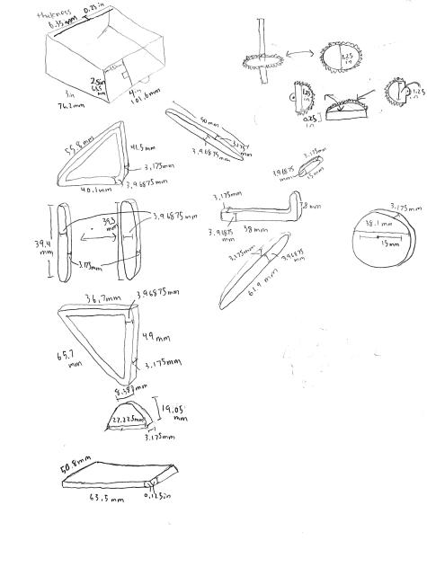
Figure 1: 3DoT Hexy Mk-01 Parts 

Parts

3D Printed Parts:

  • x1 Bottom Plate
  • x1 Top Plate
  • x2 Left Femur
  • x2 Right Femur
  • x2 Middle Femur
  • x2 Middle Tibia
  • x4 Outer Tibia
  • x6 Femur-to-Gear joint


Components:

  • x6 cotter pins
  • x10 3-.5 mm nylon lock nuts
  • x4 3-.5 mm hex nuts
  • x6 2.5 x 15 mm machine screws
  • x10 3×15 mm machine screws  
  • x4 3×30 mm machine screws
  • x4 3.5 x 15 mm sheet metal screws
  • x6  30T Ajax Scientific plastic gears
  • x4 10T Ajax Scientific plastic gears
  • x2 10T Driving gears  
  • x2 530 RPM micro gear motors
  • x2 Actobotics micro gear motor enclosure
  • x6 5×2 mm sheet metal screws
  • x4 20 mm x 3.5 mm (length/inner diameter) spacers
  • x6 3 mm x 10 mm (inner/outer diameter) washers
  • x4 3 mm x 6 mm (inner/outer diameter washers)


Required tools:

  • Philip Screw Driver
  • 3 mm hex nut driver
  • Flat tip pliers


Recommended:

Figure 2: Lucas Red “N” Tacky

Adding Lucas Red “N” Tacky grease before inserting gear shaft screws and to the gears themselves improves the performance of the cam system by reducing friction between parts.


Steps

  1. Connect femur-to-gear joint to gears. Insert 5×2 mm sheet metal screws into designated gear hole. Connect joint to gear by screwing it in until the joints bottom face comes in contact with the gear.Figure 3: Assembling gear-to-femur joint 
  2. Place Washers and gears over gear holder holes. Note 3 x 10 mm washer go on 30T gears and 3 x 6 mm washers go on 10T gears.  Figure 4: Placing washers 
  3. Insert 3×15 mm machine screws and place nylon lock nuts on the underside. Screw in nylon lock nuts, using 3 mm hex nut driver, to a desirable position that is not to tight to prevent gear rotation. Note: Adding grease to screw shaft and gear improves cam performance. 
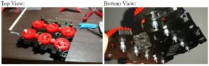
Figure 5: Placing gears, screws, and lock nuts  
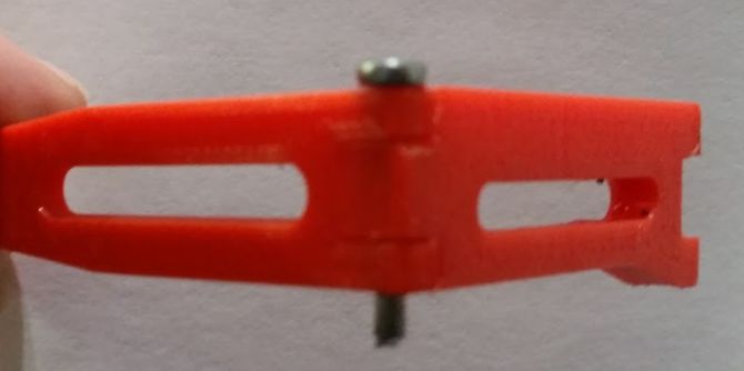
  4. Assemble legs. Mate the femur to the tibia to form elbow joint. Insert 2.5×15 mm machine screws to hold joint together. 
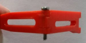
Figure 6: Assembling legs 
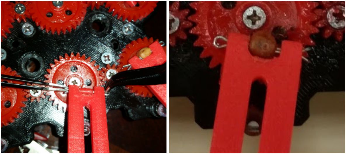
  5. Adding legs to cam system. Connect legs to femur-to-gear joint using cotter pins. After inserting cotter pins use flat head pliers to pry open the endpoints of the cotter pins. Figure 7: Adding cotter pins 
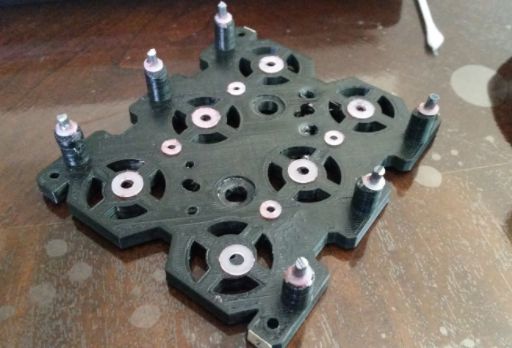
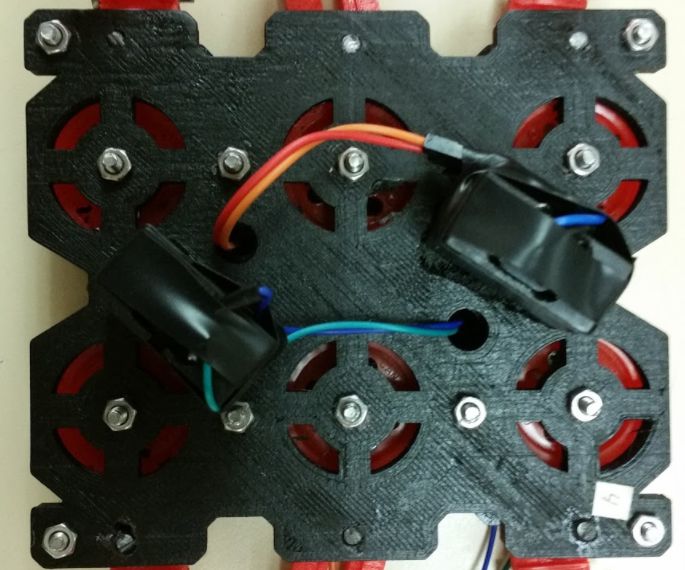
  6. Insert micro gear motor enclosures to the underside of the bottom plate and screw them in place using 3.5 x 15 mm sheet metal screws. Figure 8: Adding micro gear motors 
  7. Insert 10T Driving gears from the top plate and insert micro motors from the bottom plate. Since we are using the method A driving gear design (read above) we will need to apply a little pressure to insert gear with bushing into the shaft of the motor. 
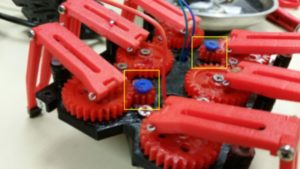
Figure 9: Adding driving gears 
  8. Insert femur’s center opening on the aluminum rods (as shown above)
  9. Place top cover, align it with the bottom plate, insert 20 mm spacers in each corner, insert 30 mm machine screws in each corner, and screw hex nuts to screws from the underside of the bottom plate. 
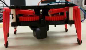
Figure 10: Adding spacers, screws, and hex nuts
  10. Run motor wires to the top plate.
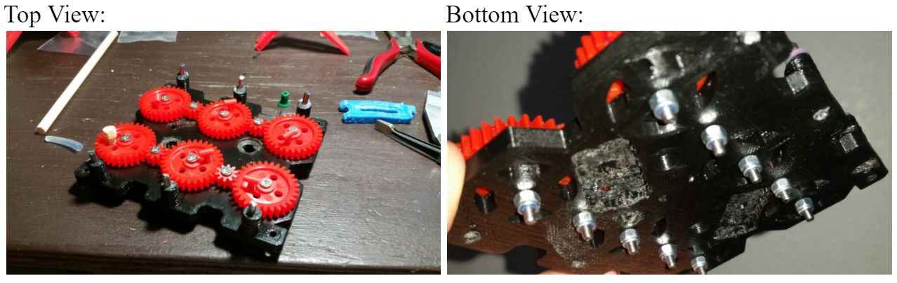
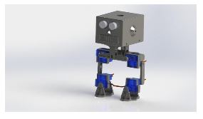
Assembled Prototype

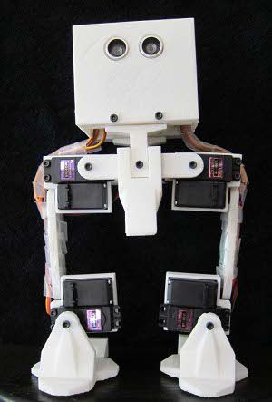
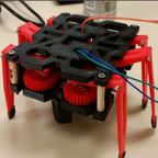
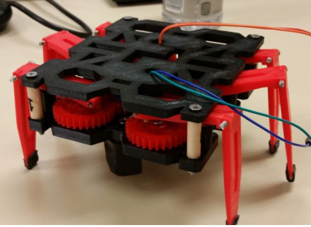
Figure 11: Hexy Mk-01

Resources


Pin Change Interrupts

By: Jordan Smallwood (Project Manager and Electronics & Control)

Approved by: Miguel Garcia (Quality Assurance)


Table of Contents

Introduction

If you think back to your days of EE 346 you’ll remember the daunting feeling of dealing with interrupts. While we barely skimmed the surface, they’re really not that troublesome. The thing to note is that there are two types of interrupts, hardware & software. Hardware interrupts take place externally from the chip such as a physical button being pressed or any kind of input changing state. Software interrupts occur internally and most likely will be the result of a timer. Hardware interrupts can be further broken down into two more categories: external interrupts and pin change interrupts. Although pin change interrupts are technically external the difference with these is that they are not pin specific, the ISR corresponding to that pin will be called any time the condition is met from any pin on that port tied to the ISR. This can be more difficult to work with than the regular external interrupts which are pin specific but the advantage of using this type is that for most AVR boards any pin can be configured as a PCINT.

For our purposes we needed six interrupts, one for each of the motors encoders and although the ATMega 2560 has 6 external interrupts two of them were on the same pin as the I2C pins SCL and SDA which meant we needed to learn something new. Which leads us to a brief discussion of PCINT.


STEP 1: Turn on Pin Change Interrupts

To turn on PCINT’s you need to configure the PCICR (Pin Change Interrupt Control Register) according to your specific purposes. This can be done the following way:

Figure 1: Pin Change Control Register and description

Since we will be routing all of our encoders to PCINT23:16 it makes sense that we should enable PCIE2. To do so we will include the line of code: [PCICR |= 0x04]. This can be done many ways but the idea is that we set that pin to 1 while keeping the other bits unchanged.


STEP 2: Pin Selection

Although any pin mapped to PCI2 will run that ISR, that is only if we set their masked bits in the Pin Change Mask Register. We only need to use 6 of the 8 pins mapped to PCI2 so we can still use the other analog-in pins if we need to later.

Figure 2: Pin Change Mask Register 2 Description

Again, we only will be wiring encoders to PCINT 16:21 so we will need to include the following line of code: [PCMSK2 |= 0x3F;].


STEP 3: Write the ISR

Now that you have configured your interrupt control registers and decided which pins are going to actively set the ISR all that is left is to tell the computer what to do when it reaches this state. Any time you ever write an ISR you should keep it as short as possible and when declaring variables make sure to make them of type volatile so it is never optimized. To define the ISR just include the following:

ISR(PCINT2_vect){} // Port K, PCINT16-PCINT23.

Finally, you will have something like this:

Figure 3: Pin Change Interrupt Example


References:

  1. https://thewanderingengineer.com/2014/08/11/arduino-pin-change-interrupts/

Spring 2018 AT-ST Sensor Testing

By: Shweta Hebbalkar (Electronics and Control – Hardware)

Verified By: Intiser Kabir (Project Manager)

Approved By: Miguel Garcia (Quality Assurance)

Table of Contents

Ultrasonic sensor – HC-SR04

Introduction

As the name implies this device uses an ultrasonic sound to measure the distance between itself and the nearest solid object. Like if we take the nature’s example then it would be like Bats detecting shapes from the sound. So with this key feature has become a staple in our projects because the last thing we want is for our project AT-ST to get the pushed out from the other robots.

Features

  • Operating Voltage: 5V DC 
  • VCC  = 5 volt power connection
  • Operating Current: 15mA
  • TRIG = trigger pin (input) 
  • Measure Angle: 15°
  • ECHO = Echo pin (output)
  • Ranging Distance: 2cm
  • 4m – GND = Ground

Theoretical Explanation of the ultrasonic sensor

Let’s look in more depth of this ultrasonic sensor so for our project we are using the HC-SR04 and it consists of two ultrasonic transducers one is used as the transmitter and another one is used as a receiver. Now when we normally operate the transmitter sends out a series of ultrasonic pulses remember the receiver despite its proximity does not pick up these pulses because ultrasonic signals are very directional. However, if an object in front of the device it will reflect the signals back to the receiver. The time delay that takes from the transmission and receiving the signal is used to calculate the distance so, for example, a longer delay will be considered as long distance and the shorter time delay will be the shorter distance. Now if we send the 5-volt, 10-microsecond pulse to the device then transmits 8 ultrasonic pulses either at the 40-kilohertz each. The echo pin will output a pulse between 100 and 50 – microsecond to 25 milliseconds and that pulse width is used to calculate the distance it will output a pulse of 38 milliseconds if there is no object detected.

Calculating the distance

To determine the distance ultrasonic signal travel at the speed of sound at 20 degrees Celsius the speed of sounds is 343 meters per second now remember the time we’re measuring with the HC-sr04 is for return trip so we’ll need to divide this in half to calculate the actual distance.

∆t=time delay

c=speed of sound (cm)

D=Distance Measured

D=∆t2*c  

As an example

D= (500/2) * 0.0343 = 8.575 cm

Experiment

Figure 1: Fritzing diagram with the Ultrasonic Sensor.

Code

Figure 2: Screenshot of the code

Output

Figure 3: Data from Arduino

Servo – Ultrasonic #1

Introduction

Servos are combined with the motor and also control electronics; this combination makes an easy to use package. The PWM signals with a periodic time of 20 milliseconds and a duty cycle of one to two milliseconds so five to ten percent. While an on time of one millisecond resents the -90-degree position of the motor shafts. 0-degree positions and the 2 milliseconds the +90-degree position. So we can rotate the shaft a total of 180 degrees. 

Features

  • Voltage: 4.8~6.0V
  • Torque: 3.5kg.cm@4.8V, 4.8kg.cm@6.0V
  • Speed: 0.17/60ТА @4.8V;0. 14/60ТА @6.0V
  • Size: 38.6×18.8×34.9mm
  • Wight: 37 g
  • Use Angle: <=160ТА

Figure 4: Fritzing diagram

Code


Figure 5: Screenshot of code

Output

Figure 6: Arduino output

Servo – Ultrasonic #2

Introduction

In this experiment, I created an object detector. So this module will scan from 0 to 180 degrees, and once its finish scanning the module will point at the object. If I displace the object, then the module will scan again from 0 to 180 degrees and trying to look for an object. This is one of the ideas for our project trying to avoid the other robots from the maze.

Fritzing diagram

Figure 7: Fritzing Diagram showing Servo and Ultrasonic

Code


Figure 8: Screenshot of code

Figure 9: Screenshot of code cont.

Output

Figure 10: Physical Demo of Servo and Ultrasonic

RGB led  

Introduction

Formerly, we were going integrate the color sensor to our robot. In order to require the decision either to take right, left, or keep going forward. Now, the color sensor is not required for our project because we change our maze requirements. But before that, I am going to explain the RGB Led to help me understand the color sensor little better. So, an RGB LED is a three LED’s in one basically 4 LED. This is a basic experiment to learn new circuit components and new programming skills.

Figure 11: RGB light connections on using fritzing diagram

Code

Figure 12: Screenshot of code

Output

Figure 13: The RCB displaying 3 different colors

Dc Motor

DC Motors that operate on direct current as opposed to motors, which operate on alternating current. We are using the small dc Motors for our project in order to move let’s look into how dc motor works. The shaft of the motor, the part that rotates is referred to an armature. On the armature, there are coils of wire these coils are connected to the commutator. The connections to the commutator are called the brushes, where the positive and negative voltage is applied. On the outside of the motor, there is a permanent magnet arranged in opposite magnetic polarity, now when dc current is applied to the commutator it sets up a magnetic field inside the coil. The coil magnets interact with permanent magnets causing the armature to rotate, now as the armature rotates the polarity is continually reversed generating the magnetic field to be reversed and the rotations to continue.

A motor driver module helps the dc motor with an Arduino, which means that dc motor will get the more current in order to, work, in other words, a current amplifier. So a motor driver is a breakout board, which consists of an L293D IC, the main purpose of the motor driver is to take a low current signal and convert it to a high current signal.

Conclusion

Due to some feedback from the Professor, we are not using RGB and will be using UV sensors with IR LEDs. We are using Ultrasonic as an avoidance mechanism. The DC motor is used to move our legs. We are planning to use servos to help control the center of gravity.

Reference

  1. https://cdn.sparkfun.com/datasheets/Sensors/Proximity/HCSR04.pdf
  2. https://www.sainsmart.com/products/ultrasonic-ranging-detector-mod-hc-sr04-distance-sensor
  3. https://components101.com/ultrasonic-sensor-working-pinout-datasheet
  4. https://www.radioshack.com/products/radioshack-standard-servo
  5. https://www.sparkfun.com/datasheets/Components/YSL-R596CR3G4B5C-C10.pdf
  6. https://nationalmaglab.org/education/magnet-academy/watch-play/interactive/dc-motor

Spring 2018 AT-ST Preliminary Model

By: Danny Pham (Manufacturing Engineer)

Verified By: Intiser Kabir (Project Manager)

Approved By: Miguel Garcia (Quality Assurance)

Table of Contents

Introduction

Our initial design included a similar concept to the Titrus III robot that involved moving the robot with servos. Since this was not ideal, we redesigned the legs to move using dc motor instead of servos and keeping the servo as a weight shift mechanism. Our design was inspired by previous velociraptor projects and an actual biped walking Theo Jansen kit.

Initial Model

For our new design, we switched from a Titrus III leg design to the Theo Jansen design. We went with the Theo Jansen design because this design works much better when it is connected to a motor and the leg can rotate in a continuous motion.

Figure 1: Theo Jansen Leg model

Description

This is the Theo Jansen design. It incorporates a motor that rotates a gear that in turn rotates a shaft connected to the leg. This will rotate the rest of the leg and create a circular walking motion for the foot. This will allow the robot to take a step.

Figure 2: Preliminary Model

Description

This is our first model that incorporated the Theo Jansen legs and split leg mechanism. I used a box for the body and implemented door hinges on the side that would act as the split leg mechanism that turns the legs. There are servos inside the box that are connected to these panels, and the servos would move the panel in and out to turn the legs. The DC motors are planted on the other side of the panels inside the box, and the motor is connected directly to the Theo Jansen leg. The motor rotates the leg and creates the walking motion for the robot.

Figure 3: Side views of Preliminary Model

Issues with the model

Some issues with the model include the distance between the legs and center of mass. Because the legs are so far apart, it makes it much more difficult to balance the center of mass when the servos are turning the legs. If we had the legs closer, the weight is closer to the center instead of the sides and it will be easier to balance the robot. The box body takes too long to print and exceeds our requirement of six hours. Also, there are issues with the foot design, and how it plants itself on the ground when it is moving in circular motion. Because it is moving in a circular motion, the foot cannot be static or else it will not stay in parallel with the ground and that will cause points of contact that will conflict with the walking motion. The previous velociraptor group used springs in order to allow the foot to move in parallel with the ground, but it was not stable and made balancing the robot harder.

Conclusion

Our new design incorporates DC motors to move the legs. We will incorporate a weight shifting mechanism in the future with a servo so that we can do robot balancing during walk motion, but for now, the servos are used to turn the legs. A future modification of the design may include less distance between the legs so that we can balance it easier and a smaller mass for the body so that we can fulfill the print time requirement.

Spring 2018 AT-ST Mechanical Drawings

By: Danny Pham (Design and Manufacturing Engineer)

Verified By: Intiser Kabir (Project Manager)

Approved By: Miguel Garcia (Quality Assurance)

Introduction

For our robot to walk and turn successfully, we will be designing elements of the robot that will be able to balance itself and move smoothly. The AT-ST walker design will incorporate parts of the Velociraptor and Biped design from previous semesters. The AT-ST will also incorporate dc motors instead of servos, so we switched out from our previous Titrus III leg design. In our case, our robot designs will be using the Theo Jansen leg design and split leg function that the previous 2017 Spring velociraptor project used.


Concept Sketches

Figure 1: initial sketches and idea of Priliminary Model

Description

For the body of the AT-ST walker, for preliminary design, we will be using a box. The box will have side panels that open and close like a door. The Theo Jansen legs will be attached to the outside of the panel, and the motor will be mounted on the inside of the side panels to connect to the legs. Another set of gears and servos inside the body will move the connector to open and close the doors, which in turn will turn the leg like split leg function.

Figure 2: initial ideal measurement of our Theo Jansen Leg

Description

This is the Theo Jansen leg design. The measurements are taken from the actual Theo Jansen leg dimensions. The width that we picked for the leg is 3.175mm because it will be made of carbon fiber and that width is sturdy enough for the carbon fiber material to support the leg.

Figure 3: 2D Sketch of Theo Jansen Legs

Description

The leg is structured so that it is not just a one dimensional build of the leg. Each component is doubled so that the leg structure is wider and that will make the leg more stable. The previous velociraptor group also included springs on the feet in order for the foot to not be parallel to the ground at all times. This will help the Theo Jansen leg motion and keep it moving.

Figure 4: Measurement Parts

Description

These are the individual measurements of each connector in the legs, and other miscellaneous parts in the body.

Conclusion

These will be the basic design of the AT-ST walker robot. The measurements used for the leg design are scaled versions of the actual model and models from the previous semesters to fit our maze and robot definitions. The measurements and shapes are subject to change once we test the function of a rapid prototype of the robot design.

Spring 2018: BiPed 3D Print Time

Written By: Miguel Gonzalez (Project Manager and Manufacturing)

Approved By: Miguel Garcia (Quality Assurance)

Update: 3D Printing Time Waiver (Approved on 5/01/2018)


Introduction

In this blog post, we will cover the overall 3D print time for the complete assembly of the Mirco FOBO. The Micro FOBO’s design is based on the original FOBO which was created by Jonathan Dowdall but utilizes updated and revised components. The design of the components will not be mention in this post but can be found in our Mechanical Design blog post. This post will explore the time it takes to manufacture parts for the Micro FOBO using a 3D printer. To better calculate the amount of time, use for fabrication I have created a table listing all the parts that are needed to assemble our robot and listed the time it takes to make it. Micro FOBO uses a total of fifteen 3D printed pieces which takes seven hours and forty-eight minutes. It is important to note that our current printing time violates our customer’s program requirement of keeping the printing time under 6 hours total. Only the head of FOBO exceeds the 2-hour limit of 3D printing requirement per part. Due to this violation, we have decided to appeal this requirement with a waiver document. By getting the approval of the customer through this appeal we won’t need to make any changes to our design or 3D printing process.

Related Requirements

Level 1 Requirements:

L1-8: Micro FOBO’s part components will be 3D printed using the material carbon fiber PLA.

L1-9: Micro FOBO will not exceed a print time of 7.80 hours. Upon approval of the waiver.

Level 2 Requirements:

L2-2: Micro FOBO dimensions will need to be small enough to fit in a 4in by 4in box for maze purposes.

L2-15: Micro FOBO shall weigh no more than the allocated mass of 460g.

Fig.1 Printing Times on Simplify3D

Table Data:

The table above shows Micro FOBO’s parts listed with their own “Build Statistics” which is information about the part’s printing time, weight, and cost of materials. This information was gathered through the slicing software, Simplify3D. All parts were listed to have a layer height of 0.20mm and 25% infill when producing the printing time information.

Final Remarks

It is important to note that the printing time shown above has been completely processed via slicing software but has been verified to be correct when printing the first full prototype. All 3D printing is done through my own 3D printer but the material (Carbon Fiber PLA) bought will be processed for reimbursement. As mentioned before, we currently exceed the amount of time allocated by the customer for printing time. The main reason we cross the six-hour mark is due to the head of FOBO requiring large amounts of support material and thus requiring more time to print out. We hope that the customer accepts our printing time waiver to allow us to keep the same head design and printing process.

References

Spring 2018: Testing Design Sketches

Written By: Miguel Gonzalez (Project Manager and Manufacturing Engineer)

Approved By: Miguel Garcia (Quality Assurance)


Table of Contents

Related Requirements

Level 1 Requirements

L1-3: Micro FOBO will have 2 legs.

L1-4: Micro FOBO will be a toy robot based on the design of the FOBO by Jonathan Dowdall.

L1-8: Micro FOBO’s part components will be 3D printed using the material carbon fiber PLA.

L1-11: Micro FOBO shall be 60% or less of the overall size of Jonathan Dowdall’s FOBO

Level 2 Requirements

L2-2: Micro FOBO dimensions will need to be small enough to fit in a 4in by 4in box for maze purposes.

L2-3: Micro FOBO will use SG90 micro servos.

Customer Requirements

C-03: The robot will be designed to be a toy for people ages 8+.

C-04: In order to minimize manufacturing cost, and packaging cost the robot shall be able to be constructed from sub assemblies within 10 minutes.

Before CAD

One of the first things we did when verifying our sketches was produced a copy of the original FOBO from www.projectbiped.com this would help in determining correct aspect ratios for the creation of the Micro FOBO. Using parts from previous semesters we managed to get all the necessary components to produce the FOBO. We 3D printed the parts for FOBO and assembled it all within the first three weeks of the semester.

Fig.1 Original FOBO Source: projectbiped.com

Fig.2 Printed FOBO


By using the printed out FOBO I was able to measure the individual parts of the robot and produce a scaled down version of each part. It mainly relied on using ratios of the larger servos compared to the micro servos our group planned on using. Figure 2 is an image that was taken after the testing of the micro FOBO parts but is a good illustration of the size comparison between the original  FOBO (in blue) and the Micro FOBO (in black).

Creating the 3D Models

After creating the Initial Design Drawings on paper I made sure to 3D model the parts on Solid Works and test how the parts fitted together. Typically we can verify how the parts work together by using Solid Works Assembly and verifying the dimensions allow the parts to fit onto the micro servos and with one another. Of course, all parts first needed to be designed before we can verify part compatibility this also included designing the micro servos, ultrasonic sensor, and custom PCB. Below you will find 3D models of parts and components that were designed in Solid Works CAD.

Fig.3 3D Model of Micro Servos

Once all the parts were 3D modeled the first compatibility test on the parts was conducted by assembling all parts together using Solid Works. This process involved virtually assembling the Micro FOBO and verifying that all parts fit together properly and that all mounting holes aligned with each other.

Fig.4 Micro FOBO Exploded Assembly

Fig.5 Micro FOBO Full Assembly


Testing the 3D Models

The last thing to do was to 3D print a prototype of the Micro FOBO and verify the results obtained from the assembly. Most parts that were printed out needed no revisions. Only the servo band and servo bracket required revisions. These parts typically required revising the mounting holes for the micro servos and slightly increasing the holes where the wires fitted through. Once the changes were applied to the model the parts were 3D printed again and verified that the issues no longer remained. We tested all designed parts by assembling a full-scale working prototype as shown below.

Fig.6 Part Verification

Fig.7 Testing Servo Fitting


Fig. 8 Part Verification with Sketches

Fig.9 Assembly Process

Fig.10 Head Verification and Assembly

References

  1. www.projectbiped.com
  2. Initial Design Drawings

Spring 2018: BiPed Initial Design Sketches

By: Miguel Gonzalez (Project Manager & Manufacturing)

Approved By: Miguel Garcia (Quality Assurance)


Related Requirements

Level One Requirements

L1-3: Micro FOBO will have 2 legs.

L1-4: Micro FOBO will be a toy robot based on the design of the FOBO by Jonathan Dowdall.

Level Two Requirements

L2-3: Micro FOBO will use SG90 micro servos.

L2-14: Micro FOBO shall measure within 4.5” x 3.25” x 7.25”.

Initial Sketches and Design

Since our robot was going to be based on the original FOBO created by Jonathan Dowdall we first needed to do some observation on his design. The original FOBO measured 24cm ( 9.5″) tall and 15.25cm ( 6″) wide. Because we are creating a miniature version of this design we can measure the servo size the original FOBO had with the micro servos we plan to use. As fig.1 shows, we can measure the two different servos and calculate their perspective ratio size with one another to give us an approximation of how small we can make our robot.

Fig.1 Calculating Ratio Sizes

Various ratios were calculated from the measurements of the two servos and we discovered that our micro version of FOBO will be approximately 60% scale of the original FOBO. This is quite a significant reduction. Now that we had our ratios and measurements of the servos we could begin by sketching some of the FOBO parts and incorporate them to suit our miniaturized robot. The servo band and servo bracket were one of the first parts to be sketched and design since these parts attached the servos onto the FOBO’s leg. Measurements from the servos and the servo horns make up the dimensions of these parts. Since the micro servos were designed to be pressure fitted onto some of the parts small tolerances where only acceptable. It was made sure to only use datasheet measurements with verified dimensions from caliper measurements.

Fig.2 Sketches of Bearing Frame and Servo Wrap

Fig.3 Body Riser Sketches

Many of the initial sketches have inaccuracies in their stated dimensions, this is due to the fact that testing and fast prototyping is needed to verify that the pieces would fit together. When designing the head of the robot it became evident that simply reducing its size by 60 percent of the original FOBO will not be sufficient. The head of micro FOBO is reliant on the size of the 3DoT board and the shield that will be mounted on it. Rough estimates on the dimension of the controller board were guessed in order to begin an initial sketching of the robot’s head. Once the head had been sketched it became evident that we can do some designs on its face to better meet the robot’s requirement of looking like a toy. This meant that we could use the ultrasonic sensors to look like eyes and thus we can design a nose and mouth to finish the face features. Antennas were also sketched on the head of the robot to simulate how toy robots looked like in the 1950s.

Fig.4 Head Sketches

Fig.5 Full Body Sketch

References

  1. http://www.projectbiped.com/prototypes/fobo
  2. 1950s Robot Toys

Spring 2018 AT-ST Product Breakdown Structure (PBS)

By: Joseph Cho (Mission, Systems, and Testing)

Verified By: Initiser Kabir (Project Manager)

Approved By: Miguel Garcia (Quality Assurance)


Introduction

The product breakdown structure below visually presents the products that will be created based on the assignments. The product breakdown structure should reflect the work breakdown structure created beforehand.

Figure 1: AT-ST Product Breakdown Structure

Description

The PBS (Product Breakdown Structure) is showing the different productions by each division. E&C (Hardware) division will be making a custom PCB shield for the sensors and gyroscope. E&C (software) division will be programming codes for movement and sensory data. Manufacturing division will be prototyping models for the body and legs of AT-ST. MST division will be customizing Arxterra control panel to have suitable commands and telemetry for AT-ST.

Reference

  1. https://www.arxterra.com/fall-2017-velociraptor-preliminary-design-document/

Spring 2018 3DoT Hexy: Spiderbot Schematic

By: Kris Osuna (Electronics and Control Engineer)

Verified by: Eduardo De La Cruz (Project Manager & Manufacturing Engineer)

Approved by: Miguel Garcia (Quality Assurance)

Table of Contents

Introduction

This blog contains the sensor shield schematic that the PCB will be based on. The schematic must contain these parts: I2C multiplex, connection to UV sensors, connection to LEDs connection to ground and power. The UV sensors, LEDs and booster are not going to be directly to the schematic. These items are going to be connected through wires so headers are going to be needed to connect them. We are getting digital pins from J3 which will be going to connect to the 3DoT. The powerI tried to make the schematic as clear as possible so the viewer can understand what is happening and which sensors are connected or related. Libraries for each product were easy to find online.

Related Requirements

Level 1 Requirements

  • The robot will need to navigate remotely through a custom-built maze (built by AoSa image), memorize the path it took, start over, and autonomously travel through the path it took.
  • The robot shall avoid collisions if it encounters other robots while navigating through the maze. This involves detecting the robot, retracing steps back, and moving to a room that allows the other robot to have a safe passage.
  • The robot shall use a v6.43 3DoT board.
  • The robot shall demonstrate the capabilities of the 3DoT micro-controller for DIY hobbyists.

Level 2 Requirements

  • The robot shall use a single RCR123A 3.7 V, 650mA rechargeable Li-ion battery to power the 3DoT board, which will power the drivetrain and all attached peripherals.
  • The robot shall use 3 UV sensors connected to a custom PCB.
  • The robot shall use a HC-SR04 ultrasonic sensor to handle robot avoidance.
  • Ultrasonic sensor shall have a range of 0.5-meter radius to detect and respond accordingly to other robots.

Update 3: Sensor Shield V3 ( April 10, 2018)

Parts

  • 4-Channel I2C
  • Gyroscope
  • 8-pin header
  • Five 4-pin headers
  • 6-pin header

Schematic now contains these parts: 4-channel I2C, gyroscope, connection to UV sensors, an 8-pin header, five 4-pin headers and a 6-pin header. The 8-pin header will connect to the 3DoT board, which will provide power, ground and four digital pins. Three of the 4-pin headers will connect to the UV sensors. A 4-pin header will connect the ultrasonic. The last 4-pin header will connect two controllable LEDs. The 6-pin header will connect to 3 LEDs. I added resistors to the digital LEDs.

Figure 1: Sensor shield schematic version 3

Update 2: Sensor Shield V2 ( April 03, 2018)

Parts

  • 4-Channel I2C
  • Gyroscope
  • 8-pin header
  • Five 4-pin headers
  • 6-pin header

A gyroscope was added to the design. The gyroscope will help identify when the robot has made a turn. The 5V power was taken out and all power will now come from the 3DoT battery. The 16-Channel I2C is now a 4-Channel I2C to save space.

Figure 2: Sensor shield schematic version 2

Update 1: Sensor Shield V1 ( March 22, 2018)

Parts

  • 16-Channel I2C
  • 8-pin header
  • Six 4-pin headers
  • 2-pin header
  • 6-pin header

Figure 3: Sensor shield schematic version 1

Resources

  1. EAGLE Training