Color Sensor Trade Study (With Cloth Maze)

By: Matt Shellhammer (Electronics & Control Engineer)

Approved by: Lucas Gutierrez (Project Manager)

Introduction

This trade study is a follow on study to the color sensor trade study which simply investigated the ranges at which the colors using electrical tape (vinyl) would be detected using the TCS34725 color sensor. In this trade study I borrowed the cloth maze from The Robot Company to run testing on it with the TCS34725 color sensor. The goal of this trade study is to help give the projects an idea of where exactly on their robots the color sensor should be mounted. Or the development team of the color sensor PCB where the color sensors should be mounted on the PCB.

Methodology

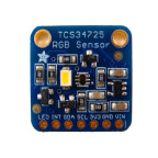
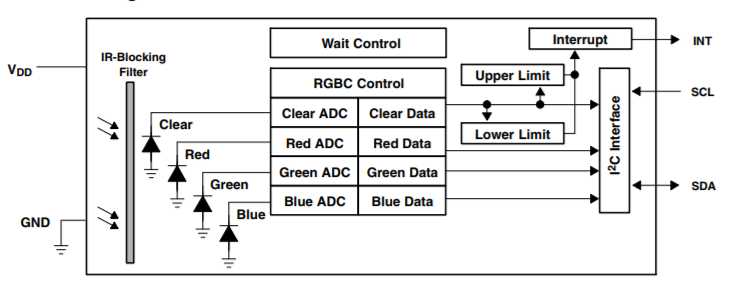
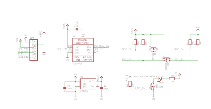
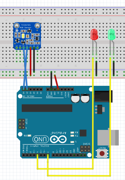
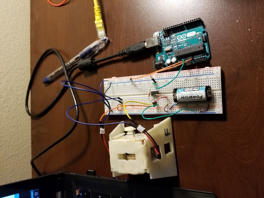
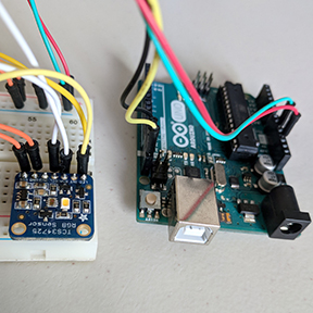
In this trade study I used two devices, the Arduino Uno, and the TCS34725 color sensor. I connected the color sensor to the Arduino Uno in the configuration shown in the table below. Additionally, to read the values from the color sensor I2C communication was used. To implement this communication the Adafruit Arduino I2C communication library was used, this library is available online on the Adafruit website.

Table 1: Interface Matrix

Arduino Uno pins

TCS34725 Color sensor pins
Vcc (3.3v) VIN

GND

GND
SDA (pin18) SDA
SCL (pin19) SCL


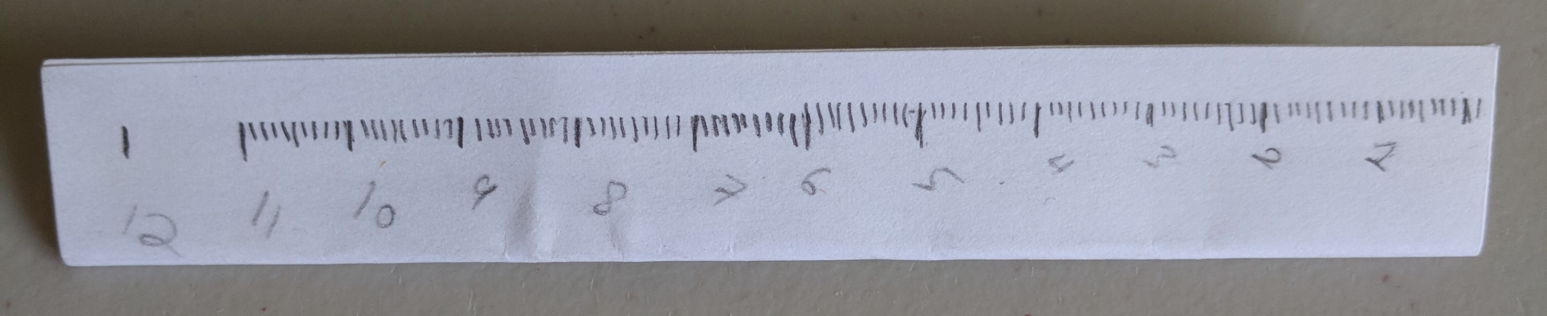
This experiment was configured similar to the original color sensor test, however the color sensor was instead this time held above the cloth maze. A piece of paper with measurement tick marks was then placed next to the maze to measure the distance from either the side of the color sensor or the distance away from the color sensor. This piece of paper was used since rulers have a gap between the beginning of the measurements and the end of the ruler, and in this experiment the measurement had to start at the maze (not above it). The paper ruler is shown below.

Figure 1: Paper ruler used to measure vertical and horizontal distance.


Now using the maze I tested the three colors on the maze: white, green, and brown to determine the optimal vertical distance (distance away from color sensor). I did this by determining where I got a peak measurement and then called that the optimal distance for that color. I also measured at what distance there was detection and at what distance there was significant detection. Significant detection is defined as reading a value greater than 1000 for any of the RBG values. The maze used is shown below and the results of the experiment are below the figure.

Figure 2: Section of the maze used showing the white, green, and brown used.

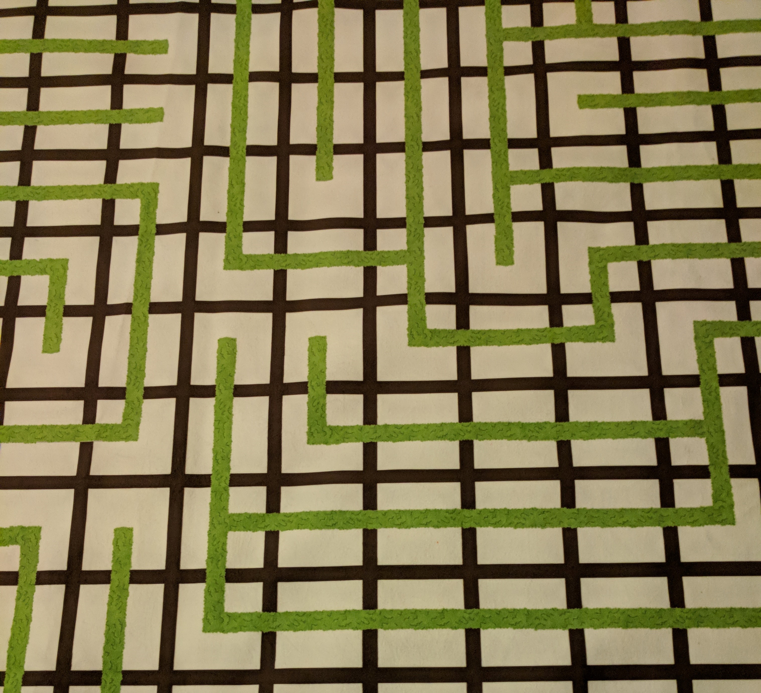
Table 2: Color and Distance Detection (Part 1)

Color Detecting

Detection distance

Significant detection distance (RGB values over 1000 recorded) Distance where max value achieved
White 8.9 cm 2 cm 1 mm
Brown 4.7 cm 0.5 cm 3 mm
Green 6.1 cm 1.6 cm 2 mm


After this test was preformed another test was performed to determine the optimal horizontal distance for the color sensor. This distance is more subjective since you want to be far enough away from the sensor to not always be detecting the lines however you don’t want the response time of your robot to be too slow. For this test I measured two distances for each color, I measured the point the color is detected as well as the point at which the amount of detection significantly spikes. The origin or zero value would be in the middle of the color sensor. I then did this from the left and the right side of the color sensor, the left and right side of the color sensor is defined as follows. In this test the color sensor was placed at 1 cm away from the maze using a stack of post it notes to elevate the sensor above the maze. I did this test only for colors green and brown because white isn’t relevant for our particular applications.


Figure 3: Test setup to show which side would be the right side of the color sensor vs which is the left.

Table 3: Color and Distance Detection (Part 2)

Color Detecting Detected horizontal distance (Top) Detected horizontal distance (Bottom) Detection spike horizontal distance (Top) Detection spike horizontal distance (Bottom)
Brown 1.2 cm 1.4 cm 3 mm 3 mm
Green 1.3 cm 1.3 cm 5 mm 5 mm


Conclusion

What can be inferred from this trade study is that a vertical distance from the color sensor within a range of 1 cm to 1 mm is a suitable range. Overall, it appeared to be that the closer to the maze (vertically) the stronger your reading would be. Additionally as long as the color sensor is at least a horizontal range of 3 to 5 mm away (zero being the center of the color sensor) from the lines there will not be any significant unintentional readings. However if trying to ensure no detection when driving straight, a distance of 9-10 mm might be desired. Testing with the project specific robot and software will also be an important factor when deciding the layout and placement of the color sensors. This trade study is to be used in supplement with testing to give the engineers a good starting point when designing the color sensor layout.

Electronic Components BOM and Order: Goliath

Written By: Muhannad Al Mohamed (Electronics & Control Division Manager)

Components

Goliath’s project uses electronic components listed in the figure below. However, an update should be made to this list in regards to the color sensing components. Since we will be using BH1745NUC IC in sensing color, the Adafruit TCS340725 should be changed along with the components of the generic color sensor. As seen on the list, some parts have been acquired by the project’s members; however, the rest should be ordered. The pricing also should be provided in order to sort all parts needed and their cost.

Update: 11/19/2017

The list for Goliath is mostly the same as listed above. However, there was one part that was added to it which is the LED Matrix (KWM-20882XWB-Y). The parts of the project are ordered and are expected to arrive the weak after Fall Break. The parts used in making the Color Sensor Shield are included as well.

Goliath ordered parts

Color Sensor Shield parts

Written By: Muhannad Al Mohamed E&C DM

Electronic Component BOM and Order: ModWheels

Written By: Muhannad Al Mohamed (E&C DM)

Components

The ModWheels project uses electronic components listed in the figure below. For now, the project is set on not making a custom PCB. However, if the members of the project decided to make a custom PCB, this list should be updated. Also, this list does not include the new color sensor (BH1745NUC) along with its related components. As seen on the list, some parts have been acquired by the project’s members; however, the rest should be ordered.

Update: 11/19/2017

The ModWheels project is still set in not making a custom PCB. The project does not need any new parts to be ordered. However, the parts of the new color sensor shield are added to the project’s list.

Color Sensor Shield parts

Written By: Muhannad Al Mohamed E&C DM

Electronic Component BOM and Order: PeteBot

Written By: Muhannad Al Mohamed (E&C DM)

Components

The PeteBot(3DoT Chassis) uses electronic components listed in the figure below. These parts include the electronic parts that would be used in making the project’s costume PCB as well. This list needs to be updated to include the new color sensor with its related components. As seen on the list, some parts have been acquired by the project’s members; however, the rest should be ordered.

Old PBot Parts list

Update: 11/19/2017

A detailed version of the parts list used by the PeteBot is added is provided in the figure below. All the parts used to make the custom PCB using the SAMBII are included too. These parts are being ordered by the members of the project are expected to arrive soon. Parts used in making the new Color Sensor Shield are included as well.

  • IC CONTROLLR LI-ION 4.2V SOT23-5 (296-27017-1-ND)
  • IC REG BOOST ADJ 1.2A SYNC 10SON (TB6612FNGC8ELCT-ND)
  • IC MOTOR DRIVER PAR 24SSOP (MCP73831T-2ACI/OTCT-ND
  • IC REG LDO 3.3V 0.5A SOT23-5 (576-1281-1-ND)
  • RF System on a Chip – SoC BLE 4.1 SOC Ultra Low Power  (556-ATSAMB11G18A-MUY
  • BATT HOLDER CR123A THRU HOLE (BH123A-ND
  • FUSE PTC RESET 8V .75A 1206 (F3370CT-ND
  • FIXED IND 4.7UH 640MA 220 MOHM (308-1947-1-ND)
  • FERRITE BEAD 120 OHM 0201 1LN (490-2557-1-ND
  • 0.1µF ±10% 16V Ceramic Capacitor X7R 0402 (1005 Metric) (490-3261-2-ND
  • 1.8pF ±0.1pF 200V Ceramic Capacitor A 0402 (1005 Metric) (478-6406-1-ND
  • 3.9pF ±0.25pF 200V Ceramic Capacitor A 0402 (1005 Metric) (478-6413-1-ND
  • 1µF ±20% 6.3V Ceramic Capacitor X5R 0402 (1005 Metric) (478-5315-1-ND
  • 2.2µF ±10% 6.3V Ceramic Capacitor X5R 0402 (1005 Metric) (478-7885-1-ND
  • 10000pF ±5% 16V Ceramic Capacitor X7R 0402 (1005 Metric) (478-3664-1-ND
  • 4.7µF Molded Tantalum Capacitors 6.3V 1206 (3216 Metric) 4 Ohm (478-8176-1-ND
  • plus/minus 20% Ceramic Cap X5R 0402 (478-10791-1-ND)
  • 1.2pF ±0.1pF 50V Ceramic Capacitor C0G, NP0 0402 (1005 Metric) (478-10145-1-ND
  • Aluminum Electrolytic Capacitors – SMD 10uF 63V (667-EEE-FK1J100P
  • LED RED CLEAR 0603 SMD (160-1447-1-ND)
  • LED YELLOW CLEAR 0603 SMD (160-1448-1-ND
  • LED GREEN CLEAR 0603 SMD (160-1446-1-ND
  • CONN USB MICRO B RECPT SMT R/A (609-4618-1-ND
  • SWITCH SLIDE SPDT 300MA 4V (563-1102-1-ND
  • 3nH Unshielded Multilayer Inductor 300mA 260 mOhm Max 0402 (1005 Metric) (712-1457-1-ND
  • 9.1nH Unshielded Multilayer Inductor 500mA 260 mOhm Max 0402 (1005 Metric) (490-8390-1-ND
  • 4.7µH Shielded Wirewound Inductor 500mA 240 mOhm 0603 (1608 Metric) (445-3607-1-ND
  • 3.3nH Unshielded Multilayer Inductor 300mA 190 mOhm Max 0402 (1005 Metric) (712-1416-1-ND
  • 2.7nH Unshielded Multilayer Inductor 300mA 170 mOhm Max 0402 (1005 Metric) (712-1415-1-ND
  • 1 kOhms ±5% 0.2W, 1/5W Chip Resistor 0402 (1005 Metric) Automotive AEC-Q200, Pulse Withstanding Thick Film   (RHM1002CT-ND)
  • 22 Ohms ±5% 0.2W, 1/5W Chip Resistor 0402 (1005 Metric) Automotive AEC-Q200, Pulse Withstanding Thick Film (RHM1012CT-ND
  • 1 kOhms ±5% 0.2W, 1/5W Chip Resistor 0402 (1005 Metric) Automotive AEC-Q200, Pulse Withstanding Thick Film (RHM1002CT-ND
  • 2 kOhms ±5% 0.1W, 1/10W Chip Resistor 0402 (1005 Metric) Automotive AEC-Q200 Thick Film  (P2.0MJCT-ND)
  • 2 MOhms ±5% 0.1W, 1/10W Chip Resistor 0402 (1005 Metric) Automotive AEC-Q200 Thick Film (P2.0KJCT-ND)
  • 220 kOhms ±5% 0.1W, 1/10W Chip Resistor 0402 (1005 Metric) Automotive AEC-Q200 Thick Film (P220KJCT-ND)
  • 10 kOhms ±5% 0.1W, 1/10W Chip Resistor 0402 (1005 Metric) Automotive AEC-Q200 Thick Film (P10KJCT-ND)
  • Thick Film Resistors 0.1watts 1Mohms 1% (660-RK73H1ETTP1004F)
  • 26MHz ±10ppm Crystal 12pF 60 Ohms 4-SMD, No Lead (SER4186TR-ND)
  • 32.768kHz ±20ppm Crystal 4pF 60 kOhms 2-SMD, No Lead (535-12373-1-ND)
  • VL6180X FlightSense™ Light, 3D Time-of-Flight (ToF) Sensor Evaluation Board (1528-1815-ND)


Updated PBot parts list

Color Sensor Shield parts

Written By: Muhannad Al Mohamed E&C DM

Electronic Component BOM and Order: Sojourner

Written by: Muhannad Al Mohamed (E&C DM)

Components

Sojourner uses electronic components listed in the figure below. However, an update should be made to this list in regards to the color sensing components. Since we will be using BH1745NUC IC in sensing color, the Adafruit TCS340725 should be changed along with the components of the generic color sensor. As seen in the list, some parts have been acquired by the project’s members; however, the rest should be ordered.

Old Sojourner’s parts list

Update: 11/19/2017

The parts list of Sojourner has changed. A Fuse part (1206L075THYR) is added to the list and the parts for the new Color Sensor Shield (Sensor shield using: BH1745NUC IC) are added too. The parts have been ordered and are expected to arrive the week after Fall Break.

Color Sensor Shield parts

Written By: Muhannad Al Mohamed E&C DM

Testing of the TCS34725 (Trade-off study)

Written by Zachary de Bruyn

Purpose

The purpose of this experiment was to test the TCS34725 RBG Color-to-Digital sensor to determine if it was applicable for the purposes of the EE400D project “PeteBot”. The testing included testing of the sensitivity of the sensor, its ability to distinguish difference between colors, and performing studies as to the limitation of the sensor.

DC Characteristics of the TCS

The TCS operates at a nominal voltage of 3-V with a maximum being 3.6-V. Depending on the state of the device, the current drawn ranges from 235-uA in an active state down to 2.5-uA in a sleep state.

DC Characteristics at the board level

The board is designed for usage with the Arduino where the VIN input is designed for 5-V, and draws XXXX A current.

The TCS34725: The TCS34725 at the component level is the physical IC located on the breakout board that reads colors and digitizes them for the benefits of the user. Therefore when referring to the TCS34725, it is in reference to the actual IC, whereas when referring to the board, it is implied that we are talking about the entire board with all IC’s and passive components.

The TCS utilizes an I2C interface with a slave address as 0x29 in hexadecimal. Therefore in order to implement multiple TCS’ within the same I2C bus, certain precautions will need to be utilized, such as an I2C extender.

The block diagram of the TCS is shown below. From the diagram it can be seen that the light entering the sensor is filtered before going through four ADC afterwhich the signal is digitized into four different color data sections: Clear, Red, Blue, Green. The digitized data is then sent via I2C bus to the respective MCU being utilized; in this case the Arduino Uno.

Figure 1: TCS Block Diagram

Breakout Board: The schematic of the breakout board is provided below, and is courtesy of Adafruit.

Figure 2: Breakout Board Eagle Schematic

As shown by the breakout board schematic, the board is powered by a 5-V input through the VIN pin on the board, and is then stepped down through an LDO (RT9193) to 3.3-V. The 5-V is also used for the source voltage for the two MOSFETs utilized in the circuit. The 3.3-V is then used as the gate voltage for the MOSFETs, and is also the input voltage necessary for the majority of the circuit including the TCS and LED MOSFET.  The breakout board also utilizes this 3.3-V and provides a 3.3-V output through the board (via pin 3, ‘+3V3’).

Test Set-Up

The purpose of this test was to determine the TCS’ ability to distinguish between colors. This test was performed by covering a square piece of cardboard with white tape, and then applying a half-inch strip of electrical tape down the center. The black tape is to simulate the lines of the maze, and the TCS’s ability to detect between colors. The basic test setup is given by Adafruit, where the VIN pin of the breakout board is powered via the 5-V of the Arduino, and the SDA and SCL inputs are connected to analog pins 4 and 5.

Figure 3: Fritzing Diagram

Next a circular wall was constructed to surround the breakout board so that testing can be done in a controlled environment which would mitigate the sensors ability to pick up any ambient light. This wall also allows us to maintain a static distance between the breakout board and the test strip that will be utilized to test the sensors ability to distinguish colors. Two LED’s were also utilized which would help determine if the correct value was being measured. When the correct color was measured (predetermined by me) the green LED would emit, else the red LED would light.

The code below was provided in the Adafruit library, and was modified in order to test the ability of the board to read colors.

/* Source provided by Adafruit and modified by Zach de Bruyn CSULB EE400D
   Connect SCL    to analog 5
   Connect SDA    to analog 4
   Connect VDD    to 5V DC
   Connect GROUND to common ground
 */

#include <Wire.h>
#include "Adafruit_TCS34725.h"

const int greenLED = 4;
const int redLED = 7;
const int fwd = 10;
const int rvs = 11;

/* Initialise with specific int time and gain values */
Adafruit_TCS34725 tcs = Adafruit_TCS34725(TCS34725_INTEGRATIONTIME_700MS, TCS34725_GAIN_1X);

void setup(void) {
  Serial.begin(9600);
  pinMode(greenLED, OUTPUT);
  pinMode(redLED, OUTPUT);

  if (tcs.begin()) {
    Serial.println("Found sensor");
  } else {
    Serial.println("No TCS34725 found ... check your connections");
    while (1);
  }

}

void loop(void) {
  readSensor();

 }

void readSensor (){
    uint16_t r, g, b, c, colorTemp, lux;

  tcs.getRawData(&r, &g, &b, &c);
  colorTemp = tcs.calculateColorTemperature(r, g, b);
  lux = tcs.calculateLux(r, g, b);

  Serial.print("Color Temp: "); Serial.print(colorTemp, DEC); Serial.print(" K - ");
  Serial.print("Lux: "); Serial.print(lux, DEC); Serial.print(" - ");
  Serial.print("R: "); Serial.print(r, DEC); Serial.print(" ");
  Serial.print("G: "); Serial.print(g, DEC); Serial.print(" ");
  Serial.print("B: "); Serial.print(b, DEC); Serial.print(" ");
  Serial.print("C: "); Serial.print(c, DEC); Serial.print(" ");
  Serial.println(" ");

 // digitalWrite(greenLED, HIGH);
  int color = r + g + b;

  Serial.print("Color: "); Serial.print(color); Serial.print(" ");

  // If black is sensed turn green LED on, else red LED is on.
  if (color < 8000 && color > 7000){
    digitalWrite(greenLED, HIGH);
    digitalWrite(redLED, LOW);
  }

  else{
    digitalWrite(redLED, HIGH);
    digitalWrite(greenLED, LOW);
  }

}

As seen in the redSensor() function. It is within this function that the sensor reads the individual digitized color. A variable ‘color’ was created which summed these values, and then these values were compared to a predefined range which would measure the black strip on the white background. In this case, the range was from 7000 to 8000.

Test Results

Video: Color Sensor Demonstration

Current Draw of GM-6 Motors

Written by Zachary de Bruyn

Purpose

The purpose of this testing is to determine the amount of current the motors draw when supplies with a CR123 – 3.7 V battery. The motors were inserted into the “3DoT Chassis” and to simulate the amount of current the motors draw when supplied with a load; in this case the weight of the chassis, running at 3.7 V.

Test Set-Up

The test utilized was performed using the Arduino Uno and a voltmeter for redundancy. The setup is displayed below in figure 1. The two GM6 DC motors were inserted into the 3DoT chassis, as shown in the figures at the end of this blog. The chassis was then anchored by string to a desk to prevent it from moving while conducting the tests.

Figure One – Test Setup

The motor load shown in figure 1 consists of two motors in parallel with a shunt resistor, R3, connected to the non-inverting input of an LM731 opamp The goal of this schematic was to drive a voltage gain at the output of the opamp that could then later be used to accurately measure the current draw of the two dc motors.

Going over some basic opamp characteristics:

  1. For ideal opamp the input resistance is infinite to both the inverting and noninverting inputs.
  2. The inverting opamp inputs drive each other to be equal, therefore:
  3. For the inverting setup as displayed in figure 1, the gain is given as:

By recalling the three basics of the opamp listed above, we can then accurately measure the voltage (vin) that is measured across the 0.5-Ohm wire resistor. At the output of the opamp, a wire was connected to the A0 pin of the Arduino Uno. The 5-V supplied by the Arduino acted as the rail for the opamp and the CR123 battery was used as the dc input to power the load (motors). The following code was then uploaded through the Arduino IDE which allowed us to use the ADC from he A0 pin to measure the voltage at the output in 1s intervals.

/* Voltage Meter code Original source credit to https://www.allaboutcircuits.com/projects/make-a-
digital-voltmeter-using-the-arduino/

Modified for uses with RC123 Battery by Zach de Bruyn CSULB EE400D*/

const float referenceVolts = 5; // The measurement of your battery
const int batteryPin = A0; // battery is connected to analog pin 0

void setup()
{
Serial.begin(9600);
}

void loop()
{
int val = analogRead(batteryPin); // read the value from the sensor
float volts = (val / 1024.0) * referenceVolts; // calculate the ratio
Serial.println(volts); // print the value in volts
delay(1000);
}

A voltmeter was used to measure the voltage over the small resistance wire as a form of redundancy and accuracy checking of the Arduino code. The experimental measurement of the wire resistor was 0.5-Ohms.

Test and Results

The voltage was read from the Arduino serial monitor which averaged at 2.46-V. This is the “vout” from the gain equation earlier. The overall gain of the system was 2, where the resistors of equal value added to the 1 of the equation. Solving for vin, we find that the vin value is 1.23-V.

Recalling the three basic opamp rules earlier, we know that the infinite input resistances of the opamp causes no current to flow through the inputs, instead, all current goes through the 0.5-Ohm shunt resistor. Because the inputs drive each other to equal zero, the shunt resistor essentially acts as a voltage divider for the circuit. Therefore, the vin calculated, is the voltage over the shunt resistor. Performing Ohm’s law, we find that the current through the load is 2.46-A, where the current is assumed to be evenly split between the two motors in parallel, implying that each motor draws 1.23-A of current.

The voltages collected from the Arduino were then gathered into Matlab and analyzed through the following code:

clear all, clc
V_m = [ % Values collected from Serial Monitor];

x = smooth(V_m, 0.3, 'loess');

plot(V_m/0.5, '.b'); grid on;
hold on
plot(x/0.5, '.r', 'linewidth', 1.5)
hold off
xlim([0, length(x)])
legend('Raw Data', 'Smooth')
xlabel('Time - sec'); ylabel('A');
title('Arduino measurements')

As we can see from the data points collected from the Matlab plot, the current fluctuated between 2.46 and 2.47 A, with an average being 2.46-A. The raw data collected every second is displayed in blue, while the averaging data is displayed in red.

Figure Two – Plotted data with trend line

Pictures of Physical Test Set-Up

Not shown are the wheels or string which suspended the movement of the chassis, however, the general understanding of the setup can be achieved with the following pictures.

Figure Three – Physical setup of circuit


What to Record: Build Algorithm

By: Matt Shellhammer (Electronics & Control Engineer)

Approved by: Lucas Gutierrez (Project Manager)

Table of Contents

Introduction

To navigate throughout the maze we must record and update the information about the robots location within the maze. This will be done by using the maze stored in program memory, a two dimensional array to store information about direction and intersections, and a subroutine called “enterRoom”.

Methodology

To update the information about the maze as navigating throughout the maze I have developed a subroutine called “enterRoom”. What this subroutine does is calls three additional subroutines: “turnInMaze”, “stepInMaze”, and “roomInMaze”. I developed all of these subroutines using a structure called robot_inst that includes the following information: direction, turn, row, column, room, and bees. Then when calling these subroutines I simply send an instance of this structure to the subroutine and then store the result of enterRoom within that instance.

The subroutine turnInMaze uses the turn and direction values from the robot_inst structure and return a new direction value within robot_inst.

The subroutine stepInMaze uses the direction, row, and column values from robot_inst to return updated row and column values within robot_inst.

The subroutine roomInMaze uses the current row and column values to update the room and bees values within robot_inst.

Software

Main .ino file

////////////////////////////////////////////////////////////////
//  Name     : Update room                                                 
//
//  Author   : Matt Shellhammer                                                        
//
//  Date     : 18 October, 2017                                           
//
//  Version  : 1.0                                                                                      //
////////////////////////////////////////////////////////////////

#define __PROG_TYPES_COMPAT__ // __PROG_TYPES_COMPAT__
#include <avr/pgmspace.h>
#include "maze.h"

void setup() {
  Serial.begin(9600);
  delay(5000); 
}

void loop() {
  // Robot is outside of maze in the bottom left corner
  // Initialization within structure prototype
  static myRobot_t robot_inst;    // create an instance of myRobot_t called robot_inst
  static boolean newRoom = 0;
  static uint8_t room_idx = 0;
  // If we make a turn in the real world then we have to update robot_inst.turn
  // to match the turn exicuted in the real world.
  if (newRoom == 1){
    robot_inst = enterRoom(robot_inst);
    currRow = robot_inst.maze.row;
    currCol = robot_inst.maze.col;
    nextDir[room_idx] = robot_inst.dir;
    room_idx++;
    newRoom = 0;
  }
}

Virtual instructions

myRobot_t enterRoom(myRobot_t current){
  current = turnInMaze(current);
  current = stepInMaze(current);
  current = roomInMaze(current);
}

myRobot_t turnInMaze(myRobot_t current_1){
  // index = 4*turn_val + dir_val
  uint8_t index = (current_1.turn << 2) + current_1.dir;
  current_1.dir = pgm_read_byte_near(turn_table + index);
  return current_1;
}

myRobot_t stepInMaze(myRobot_t current_2){
  // index = 2*current_2.dir
  uint8_t index = (current_2.dir << 1);
  current_2.maze.row += pgm_read_byte_near(map_table + index);      // Add either -1, 0, or 1 to current
// row value.
  current_2.maze.col += pgm_read_byte_near(map_table + index + 1);  // Add either -1, 0, or 1 to current
// column value.
  return current_2;
}

myRobot_t roomInMaze(myRobot_t current_3){
  // index = 21*current_3.maze.row + current_3.maze.col
  uint16_t index = (21*current_3.maze.row) + current_3.maze.col;
  uint8_t maze_val = pgm_read_byte_near(theMaze + index);
  current_3.room = maze_val & 0x0F;                      // clear upper nibble and store as the room value
  uint8_t temp_bees = (maze_val & 0xF0) >> 4;     // clear lower nibble and store as the temp bees value
  current_3.bees += temp_bees;                            // add temp_bees to curret bees value
  return current_3;
}

Header file

// Autonoumous maze arrays
uint8_t currRow;
uint8_t currCol;
uint8_t nextDir[256] = {0};

struct coord_t{
  uint8_t row = 0x13;
  uint8_t col = 0x00;
};

struct myRobot_t{
  uint8_t dir = 0x03;   // Robot is initially facing north
  uint8_t turn = 0x00;  // First action is no turn
  coord_t maze;
  uint8_t room = 0x00;  // Initial room is empty
  uint8_t bees = 0x00;  // No bees present
};

//Compass   S     E     W     N
//dir       00    01    10    11

const uint8_t turn_table[] PROGMEM =
          {0b00, 0b01, 0b10, 0b11, // 00 no turn
           0b10, 0b00, 0b11, 0b01, // 01 turn right
           0b01, 0b11, 0b00, 0b10, // 10 turn left
           0b11, 0b10, 0b01, 0b00  // 11 turn around
           };

//  row   col   dir

const int8_t map_table[] PROGMEM =
    {1  ,  0, // 00
     0  ,  1, // 01
     0  , -1, // 10
    -1  ,  0  // 11
    };

const int maze_length = 399;

const uint8_t theMaze[] PROGMEM =

// 00  01   02   03   04   05   06   07   08   09   0A   0B   0C   0D   0E   0F   10   11   12   13   14
{0x05,0x09,0x09,0x09,0x09,0x09,0x01,0x03,0x05,0x09,0x09,0x09,0x09,0x09,0x09,0x09,0x29,0x09,0x09,0x09,0x02,  // 00
 0x0C,0x09,0x09,0x03,0x05,0x09,0x0A,0x06,0x06,0x05,0x09,0x09,0x09,0x09,0x09,0x09,0x09,0x03,0x05,0x03,0x06,  // 01
 0x05,0x09,0x0B,0x06,0x06,0x05,0x09,0x0A,0x06,0x0C,0x09,0x09,0x09,0x09,0x09,0x01,0x0B,0x0C,0x0A,0x06,0x06,  // 02
 0x06,0x0D,0x09,0x0A,0x06,0x06,0x05,0x03,0x0C,0x09,0x09,0x03,0x05,0x09,0x09,0x0A,0x05,0x09,0x09,0x08,0x02,  // 03
 0x06,0x05,0x09,0x09,0x0A,0x06,0x06,0x0C,0x09,0x09,0x09,0x0A,0x0C,0x09,0x09,0x03,0x06,0x05,0x09,0x09,0x0A,  // 04
 0x06,0x0C,0x03,0x05,0x09,0x02,0x06,0x05,0x09,0x09,0x09,0x09,0x09,0x09,0x03,0x06,0x06,0x0C,0x03,0x05,0x03,  // 05
 0x06,0x05,0x0A,0x0C,0x03,0x06,0x06,0x06,0x05,0x01,0x03,0x07,0x05,0x03,0x06,0x06,0x06,0x05,0x0A,0x06,0x06,  // 06
 0x06,0x0C,0x09,0x03,0x0E,0x0C,0x04,0x02,0x06,0x06,0x06,0x06,0x06,0x06,0x0C,0x02,0x06,0x0C,0x06,0x02,0x06,  // 07
 0x06,0x05,0x0B,0x0C,0x09,0x09,0x09,0x04,0x02,0x06,0x06,0x06,0x06,0x0C,0x09,0x0A,0x04,0x09,0x0B,0x06,0x06,  // 08
 0x0C,0x08,0x09,0x09,0x09,0x09,0x01,0x01,0x02,0x06,0x0C,0x08,0x08,0x09,0x01,0x09,0x08,0x09,0x03,0x06,0x06,  // 09
 0x05,0x01,0x09,0x09,0x0B,0x07,0x06,0x04,0x02,0x0C,0x09,0x09,0x09,0x03,0x04,0x09,0x03,0x07,0x06,0x06,0x06,  // 0A
 0x06,0x0C,0x09,0x09,0x09,0x02,0x06,0x04,0x02,0x0D,0x09,0x09,0x09,0x0A,0x0C,0x03,0x06,0x06,0x06,0x06,0x06,  // 0B
 0x06,0x05,0x09,0x09,0x09,0x0A,0x06,0x0C,0x0A,0x05,0x09,0x09,0x09,0x09,0x03,0x06,0x06,0x06,0x06,0x06,0x06,  // 0C
 0x06,0x0C,0x09,0x09,0x09,0x03,0x04,0x09,0x09,0x08,0x0B,0x05,0x03,0x05,0x0A,0x06,0x06,0x06,0x06,0x06,0x06,  // 0D
 0x04,0x09,0x09,0x09,0x09,0x08,0x02,0x05,0x01,0x09,0x03,0x06,0x06,0x06,0x05,0x0A,0x0E,0x06,0x06,0x06,0x06,  // 0E
 0x06,0x05,0x09,0x09,0x09,0x09,0x0A,0x0E,0x06,0x07,0x06,0x06,0x06,0x06,0x06,0x05,0x09,0x0A,0x06,0x06,0x06,  // 0F
 0x06,0x0C,0x09,0x09,0x09,0x09,0x09,0x09,0x0A,0x06,0x06,0x06,0x06,0x0E,0x0E,0x06,0x05,0x09,0x0A,0x06,0x06,  // 10
 0x04,0x09,0x09,0x09,0x09,0x09,0x09,0x09,0x09,0x0A,0x0C,0x0A,0x06,0x05,0x09,0x0A,0x06,0x0D,0x09,0x0A,0x06,  // 11
 0x04,0x09,0x09,0x09,0x09,0x09,0x09,0x09,0x09,0x09,0x09,0x09,0x08,0x08,0x09,0x09,0x08,0x09,0x09,0x09,0x0A,  // 12
};

3DoT v4.54 ModWheels Implementation

By: Matt Shellhammer (Electronics & Control Engineer)

Approved by: Lucas Gutierrez (Project Manager)

Introduction

ModWheels was given a 3DoT v4.54 board and we have attempted to do testing on this board to begin developing software and custom commands for the robot. When attempting to upload the 3DoT basic example from my computer and interface to the 3DoT v4.54 board through the Arxterra app to move the motors there appeared to be no functionality.

Methodology

After meeting with Chris to troubleshoot the issues I was able to upload code that moves the motors without interfacing through the Arxterra app. I still have not been able to upload software to the 3DoT board that will interface through the Arxterra app to move the motors.

I will now be going through the 3DoT training document section 12 ‐ Arxterra Bluetooth Wireless Communication and running tests following through this document to diagnose the current issues. Once I have determined the leading issue and I am able to interface the 3DoT board through the Arxterra app I will upload an updated blog post explaining the process and the problems solve/encountered.

How To Record & What To Record

By: Matt Shellhammer (Electronics & Control Engineer)

Approved by: Lucas Gutierrez (Project Manager)

Introduction

To navigate the maze autonomously we will have to store data about the path traveled while in RC mode (direction, row, & column). This data then be used when switching to RC mode to replicate the actions that were taken in RC mode.

Methodology

When navigating the maze in RC mode the robot should store the direction when it detects that it has entered a new room with an intersection and executes a turn. It should store the new direction that the robot is facing after executing the turn. This direction should be stored in a two dimensional array where the intersection number is in one row and the direction traveled for that intersection is stored in the next row. The robot should store the row and column in variables that are constantly being updated to allow for the robot to know where it is at any time. In addition when it completes the maze those variable can be used to verify it truly completed the maze. A subroutine can be executed when the maze was finished and the user exits (or stops) RC mode to store the final row and column value and check that the maze was completed.

Turns should be predefined by each project as a command that executes a right or left turn and then stores the new direction in the two dimensional array. This allows for turns to be executed in a single button push and makes determining when a turn was executed relatively straight forward.

Source Material

Featured Image: https://forums.xilinx.com/t5/Spartan-Family-FPGAs/S6-Multiboot-Golden-Image-Header-Redux/td-p/243836