
Pete-Bot Custom Command and Telemetry
Written by Elizabeth Nguyen (Project Manager)
Description:
A short list of custom commands and custom telemetry are defined in preparation for the EE 400D Fall 2017 Mission.
Custom Commands
- Adjustable Speed Commands – Allows the robot to run at a specific set speed
- Option for slowest speed
- Option for medium speed
- Option for fastest speed
- On/Off for adjustable speed
- Emergency On/Off Command – in the case that the robot is incapable of operating in Phase 2b
- This is to avoid damage to the robot and other robots
- Avoids the need for anyone to step into the maze and pick up the robot to disable it
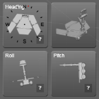
Custom Telemetry
- Display of Phase the robot is operating in
- Robot detected
- State that the robot is in during robot avoidance


Goliath Fall 2017 – Recommended Custom Telemetry & Custom Commands
The purpose of this document is to define telemetry visuals and custom commands required in Arxterra to control the Goliath during the mission. These definitions will be used in the software design on both the application side and the internal operating code of the Goliath. These commands may be subject to change if some are not possible […]

Mission Definition
Written by Elizabeth Nguyen (Project Manager)
Table of Contents
Objective:
The total time for each phase of the mission set is determined in order to ensure there is enough time allocated for the entire mission set to be completed in 120 min.
This document entails the breakdown of the mission set and how much time is split for each phase based on the maximum speed of each robot as provided in Mission Duration at Maximum Speed.
Phases:
- Phase 1 – Record
- Phase 2a – Individual Playback
- Phase 2b – 4 Robots, 1 Maze
- Phase 2c – Individual Playback (Pre-defined)*
* Phase 2c is optional and based on the success of Phase 2a
Robot Order: (from fastest to slowest)*
- Pete-Bot** – 6 min.
- ModWheels** – 7 min.
- Sojourner** – 14 min.
- Goliath – 18 min.
* All times have been rounded up
** Assumes no load
Speeds & Path Durations used:
Path durations were calculated and documented by Railan Oviedo. There are two documents where one addresses the path duration at maximum speed and another at minimum speed.
The bolded texts indicate which numbers I used to determine allocated time.
Types of Path Scenarios:
- Shortest Path Scenario
- Average Path Scenario
Speeds:
- Half Speed – Min Speed
- Half Speed – Max Speed
- One-Third Speed – Min Speed
- One-Third Speed – Max Speed
One-third speed was chosen (and suggested by Mark Huffman) to account for potential decrease in time due to added weight (since all but one robot have provided speeds under no load conditions). Although half-speed would be better to use for worst-case scenarios, it may not be as reasonable either. Also, average path durations were chosen to determine total time allocations at worst.
Breakdown of Mission Set:
- Phase 1 – Record
- Average Path Scenario at One-Third Speed (Max Speed)
- Total Time: 54 min.
- Path completion: 45 min.
- Rotation: 3 min. x 3 rotations = 9 min.
- Total Time: 54 min.
- Concluded Total Time: 60 min.
- Rounded up in the case that rotations are not 3 min. each or that some robots end up not performing up to speed due to added weight.
- Average Path Scenario at One-Third Speed (Max Speed)
- Phase 2a – Individual Playback
- Concluded Total Time: 60 min.
- Considering that this phase is to test if the robot has properly recorded the maze, it can be assumed that the amount of time it takes to individually playback each robot is the same as Phase 1.
- Assuming that there is only one maze available, this means that the amount of time to complete the mission set has been allocated to both Phase 1 and Phase 2a.
- Alternative: (has been approved by Hill)
- If two mazes are available, then Phase 1 and Phase 2a can occur simultaneously.
- Once one robot completes Phase 1, it may proceed to Phase 2a on the second maze.
- This would allow Phase 1 || Phase 2a to be completed in 60 min.
- Concluded Total Time: 60 min.
- Phase 2b – 4 Robots, 1 Maze
- Concluded Total Time: 20 min.
- Total time is based on the time it takes for the slowest robot (Goliath) to playback its recorded path. At worst, that is 18 minutes; however, including factors such as robots potentially detecting each other and having to avoid each other, 2 minutes has been added in.
- Note: At this time, it is unknown how long it will take a robot to execute the Robot Avoidance Code and recover from its detour.
- If it takes even longer for a robot to avoid another, maybe a rule should be made where if a robot takes three attempts to correct itself and fails, then it fails Phase 2b and should be removed from the maze.
- Total time is based on the time it takes for the slowest robot (Goliath) to playback its recorded path. At worst, that is 18 minutes; however, including factors such as robots potentially detecting each other and having to avoid each other, 2 minutes has been added in.
- Concluded Total Time: 20 min.
- Phase 2c – Individual Playback with Pre-Defined Maze
- This Phase only occurs if a robot fails to complete Phase 2a.
- Best Case: 0 min.
- All four robots must complete Phase 2a successfully.
- Worst Case: 60 min.
- All four robots fail to complete Phase 2a.
- Duration based on the number of robots at best and at worst in minutes:
[Mission Set Table] - Disassembly & Reassembly
- Total Time: 20 min.
- Based on Natalie Arevalo’s conclusion
- Disassembly: 10 min.
- Reassembly: 10 min.
- Based on Natalie Arevalo’s conclusion
- Total Time: 20 min.
Scenarios:
- Best Case Scenario – 100 min.
- Reasoning:
- Phase 2c is not required
- Phase 1 || Phase 2a (two mazes are required)
- Breakdown:
- Phase 1 || Phase 2a – 60 min.
- Phase 2b – 20 min.
- Phase 2c – 0 min. (if all robots succeed in Phase 2a or if Phase 2c is not included)
- Disassembly & Reassembly – 20 min.
- This scenario has been selected for the demonstration date on December 13, 2017.
- Reasoning:
- Worst Case Scenario – 160 min.
- Reasoning:
- Phase 2c is not required
- Phase 1 and Phase 2a occur separately
- Breakdown:
- Phase 1 – 60 min.
- Phase 2a – 60 min.
- Phase 2b – 20 min.
- Phase 2c – 0 min.
- Disassembly & Reassembly – 20 min.
- Reasoning:
- Absolute Worst Case Scenario – 220 min.
- Reasoning:
- Phase 2c occurs with all four robots
- Phase 1 and Phase 2a occur separately
- Breakdown:
- Phase 1 – 60 min.
- Phase 2a – 60 min.
- Phase 2b – 20 min.
- Phase 2c – 60 min.
- Reasoning:
- Disassembly & Reassembly – 20 min.
Mission Duration at Maximum Speed
Descriptions, Calculations, and Images by Railan Oviedo (Manufacturing)
Description:
In order to calculate the mission duration, multiple paths were created and averaged in order to have a rough estimate on the time length. These paths were made intentionally long in distance so as to simulate worst-case scenario situations. Based on the given speeds of the robot*, the longest time to complete the average calculated path is 17.69 minutes (Goliath). Further calculations were made for the shortest possible path, and differences in time based on the average speed used by the robot (Either Half-Speed or One-Third Speed).
*P-Bot and ModWheels speeds were calculated assuming the motors are running are 5 V
Updated on 11/17/2017.
Methods of Calculation
First, the shortest path possible will be calculated in order to determine the best case scenario mission duration. Then, 6 long maze paths—which will start and end at the entrance and exit of the maze—will be created (4 of which will be off-shoots of the first 2) and their distance will be averaged in order to simulate any given run through the maze.
To calculate the time that a particular robot will take to navigate the averaged path, their provided speed will be reduced by a third—and another scenario with the speed reduced by a half—due to the fact that it will likely move slowly to maintain contact with the colored line. Furthermore, for every turn, an extra 2 seconds will be added to account for the action; and for every U-turn, an extra 6 seconds will be added to account for the action.
Robot Speeds:
All robot speeds besides Goliath are at no-load based off of calculations from the wheel diameter and the RPM of the robot’s given motor.
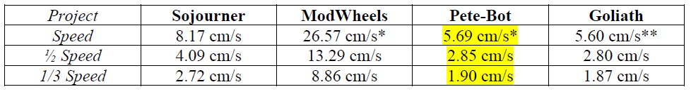
Table (1) – Robot Speeds
* These speeds assume a constant 5V supply to the motors, thus resulting in an RPm of 64
** Goliath’s speed is provided under their estimated weight conditions
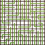
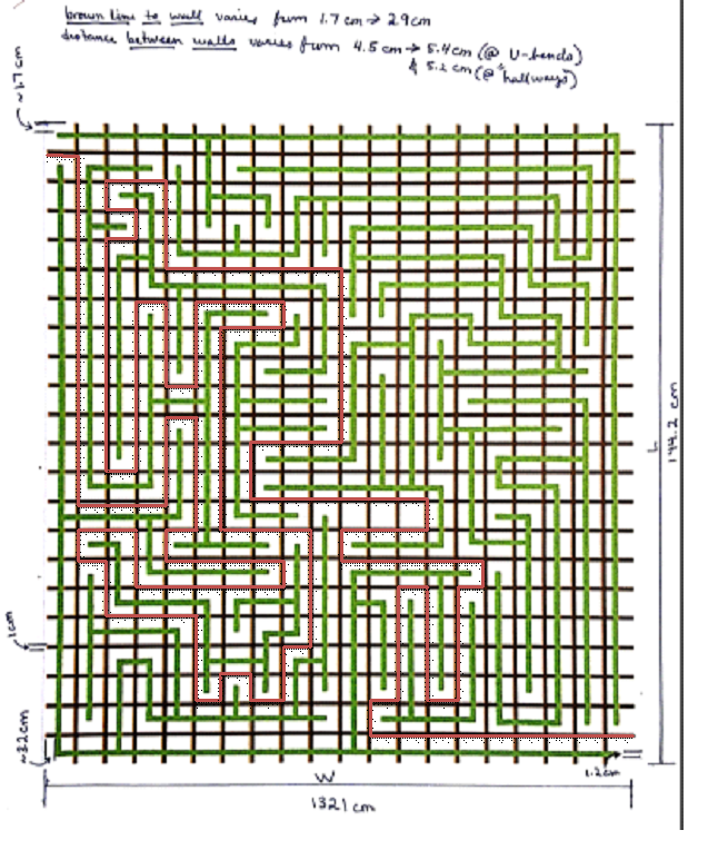
Maze Calculations
Reference for Maze Dimensions by Zachary de Bruyn
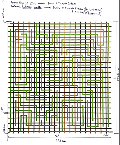
Image of Maze with Dimensions
One strip of brown is approximately 6.61 cm (132.1 cm/20 cm).*
*U-Turns will not be counted as a strip traveled and are only factored into the aformentioned 6 sec./U-Turn condition.

Shortest Possible Path
- Total Number of Turns: 12
- Time to be added: 12 * 2 sec. = 24 sec.
- Total brown strips covered: 52
- Linear distance: 52 * 6.61 cm = 343.72 cm = 3.4372 m.
Longest Path Option 1a
- Total Number of Turns: 62
- Time to be Added: 62 * 2 sec. = 124 sec.
- Total brown strips covered: 170
- Linear Distance: 170 * 6.61 cm = 1,123.7 cm = 11.24 m.

Longest Path Option 1b
- Total Number of Non U-Turns: 62 + 8 + 8 = 78; Total Number of U-Turns: 3
- Time to be Added due to Non U-Turns: 78 * 2 sec. = 156 sec.
- Time to be Added due to U-Turns: 3 * 6 sec. = 18 sec.
- Total brown strips covered: 170 + 28 + 10 + 6 = 214
- Linear Distance: 214 * 6.61 cm. = 1,414.54 cm = 14.15 m.
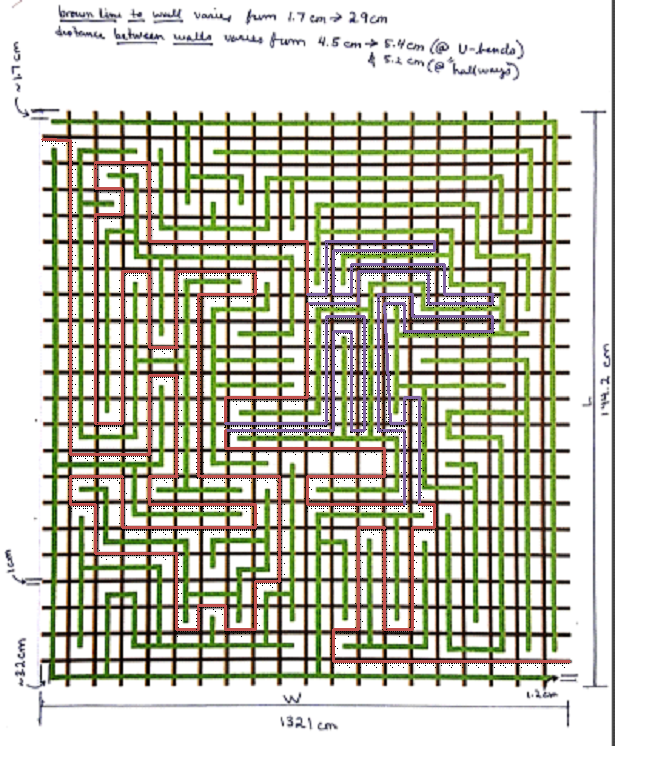
Longest Path Option 1c
- Total Number of Non U-Turns: 62 + 14 + 8 + 12 = 96; Total Number of U-Turns: 5
- Time to be Added due to Non U-Turns: 96 * 2 sec. = 192 sec.
- Time to be Added due to U-Turns: 5 * 6 sec. = 30 sec.
- Total brown strips covered: 170 + 26 + 30 + 30 = 256
- Linear Distance: 256 * 6.61 cm. = 1,692.16 cm. = 16.92 m.
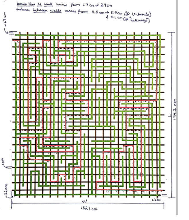
Longest Path Option 2a
- Total Number of Turns: 80
- Time to be Added: 80 * 2 sec. = 160 sec.
- Total brown strips covered: 208
- Linear Distance: 208 * 6.61 cm. = 1,374.88 cm. = 13.75 m.
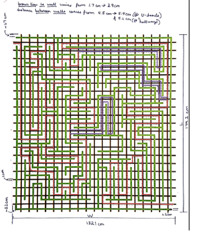
Longest Path Option 2b
- Total Number of Non U-Turns: 80 + 2 + 10 + 8 = 100; Total Number of U-Turns: 3
- Time to be Added due to Non U-Turns: 100 * 2 sec. = 200 sec.
- Time to be Added due to U-Turns: 3 * 6 sec. = 18 sec.
- Total brown strips covered: 208 + 24 + 24 + 26 = 282
- Linear Distance: 282 * 6.61 cm. = 1,864.02 cm. = 18.64 m.

Long Path Option 2c
- Total Number of Non U-Turns: 80 + 8 + 6 + 4 = 98; Total Number of U-Turns: 3
- Time to be Added due to Non U-Turns: 98 * 2 sec. = 186 sec.
- Time to be Added due to U-Turns: 3 * 6 sec. = 18 sec.
- Total brown strips covered: 208 + 28 + 40 + 22 = 298
- Linear Distance: 298 * 6.61 cm. = 1,969.78 cm. = 19.70 m.
Results:
After calculating all the numerical values, the following tables have been compiled.

Table (2) – Total Linear Distance, Added Time, and Average Values
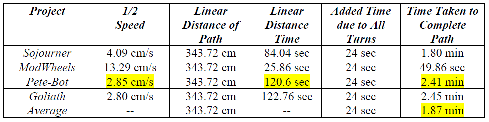
Table (3) – Shortest Mission Duration at Half-Speed (Shortest Path Scenario)
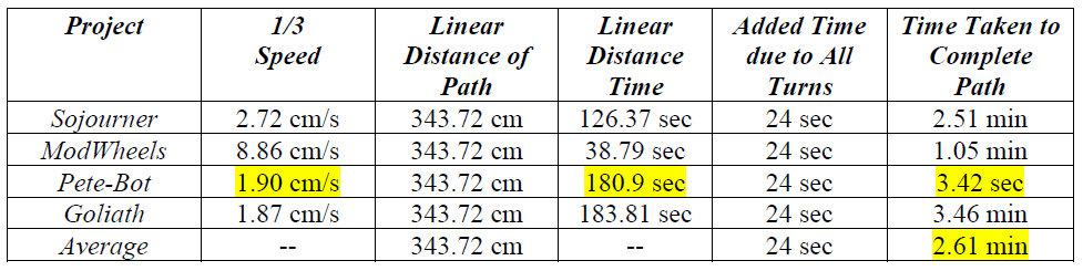
Table (4) – Shortest Mission Duration at One-Third Speed (Shortest Path Scenario)
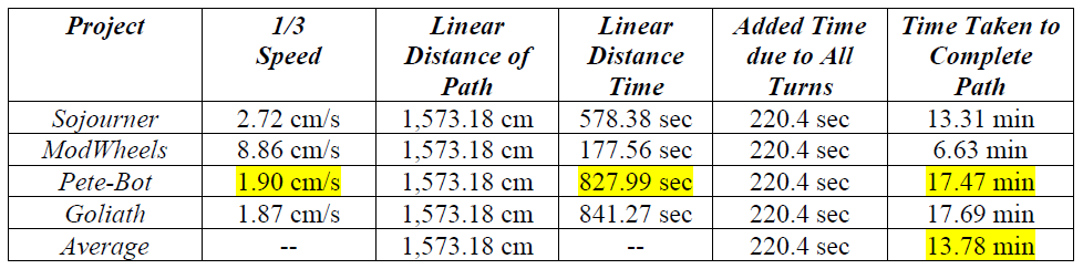
Table (5) – Average Mission Duration at One-Third Speed (Average Path Scenario)
Final Notes
These estimations do not factor into account the time it would take to navigate a path that starts at a random point in the maze. However, since the created paths are incredibly large—in order to simulate a worst-case scenario—it is safe to assume that, in practice, the total time taken to navigate any given path will be less than the calculated values. This also assumes that the processes of turning or U-turning do not require considerably more amount of time to execute than originally assumed.

Maze Dimensions
Written by Elizabeth Nguyen (Project Manager)
Measurements taken by Zachary de Bruyn (Electronics & Control)
Dimensions:
- Total width: 132.1 cm.
- Total length: 144.2 cm.
- Brown line to wall (green line) varies from 1.7 cm to 2.9 cm.
- Distance between walls varies:
- 4.5 cm to 5.4 cm @ the U-bends
- 4.5 cm to 5.2 cm @ hallways
- Thickness of horizontal brown lines is 1 cm.
- Thickness of vertical brown lines is 1.2 cm.
Scan of Maze with Dimensions
Disassembly and Reassembly Guidelines and Rules
By: Natalie Arevalo (Design & Manufacturing Engineer)
Approved by: Lucas Gutierrez (Project Manager)
Table of Contents
Introduction
The customer requested for there to be specific rules and guidelines for the disassembly and reassembly portion during the day of Mission Launch. In order to compile a comprehensive list of rules and guidelines, a set of questions were sent to the project managers in regards to disassembly and reassembly. With the initial input from the project manager, an initial document was composed outlining the intended rules and guidelines. After a brief review of this document by the project managers, minor adjustment were made to the list. The current list of the rules and guidelines for disassembly and reassembly are listed below.
Guidelines and Rules
Time Allotted
- Disassembly: 10 minutes
- Reassembly: 10 minutes
Rules for Dissassembly
- All robot will be disassembled by the E&C and Manufacturing engineers – 2 engineers in total.
- All teams will disconnect all electronics connected to the 3Dot board.
- All 3Dot boards will be clear of electronics
- All teams will disconnect motors
- Project specific disassembly guidelines:
- Sojourner
- Disassemble rover body
- Disassemble suspension system
- Disconnect all sensors
- Goliath
- Remove panels
- Remove tracks
- Disconnect all sensors
- P-Bot
- Disassemble robot body
- Disconnect wheels
- Disconnect all sensors
- ModWheels
- Disconnect wheels and front axle
- Disassemble chassis
- Disconnect all sensors
- Sojourner
Rules for Assembly
- All robots will be reassembled by the E&C and Manufacturing engineers – 2 engineers total.
- All teams will be allowed to use a cable tree as well as an assembly diagram as necessary.
- All robots will be tested after reassembly to confirm its functionality.
- Test will be conducted using the Arxterra App
- Robot should be able to go forwards
- Robot should be able to go backwards
- Robot should be able to do a right turn
- Test will be conducted using the Arxterra App
Source Material:
Feature Picture: https://www.assemblymag.com/blogs/14-assembly-blog/post/91291-taking-stuff-apart
Fall 2017: ModWheels 3D Model
By: Natalie Arevalo (Design & Manufacturing Engineer)
Approved by: Lucas Gutierrez (Project Manager)
Table of Contents
Introduction
As part of the ModWheels team, I was asked to make various modifications to the existing model of the KidStuff’s car. Additionally, a new part was designed and integrated into the modified model. More parts will be designed in the future as holders for additional components. However, the following blog post expands on the modifications mentioned above as well as the newly designed part. The blog post ends with the full assembly of the ModWheels model.
Model Designs
Top and Bottom Panels
Both the top and bottom parts of the chassis were altered to accommodate 3DoT 5.03. The main changes involved moving the opening for the battery holder as well as the access points for the pin headers on the top part of the chassis. For the bottom of the chassis, the accesses points for the bluetooth module and the color shield were also moved. Additionally, holes were made in which dawls would be placed to put a platform on top of them to hold a phone. Lastly, holes were made on the top and bottom of the chassis to place zip ties which will hold wires out of the way of any moving parts. All of these changes can be seen below.
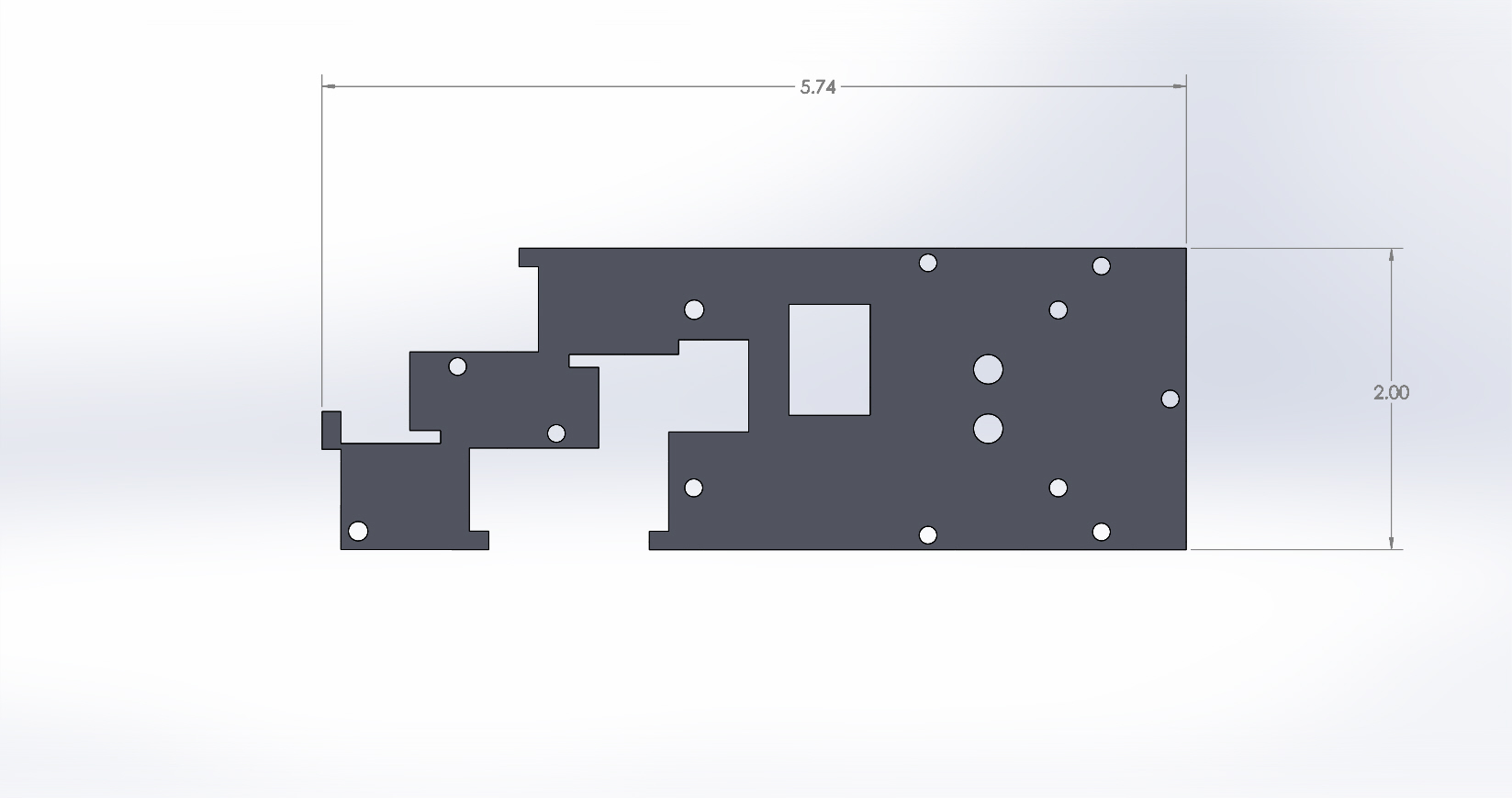
Figure 1: Bottom Panel
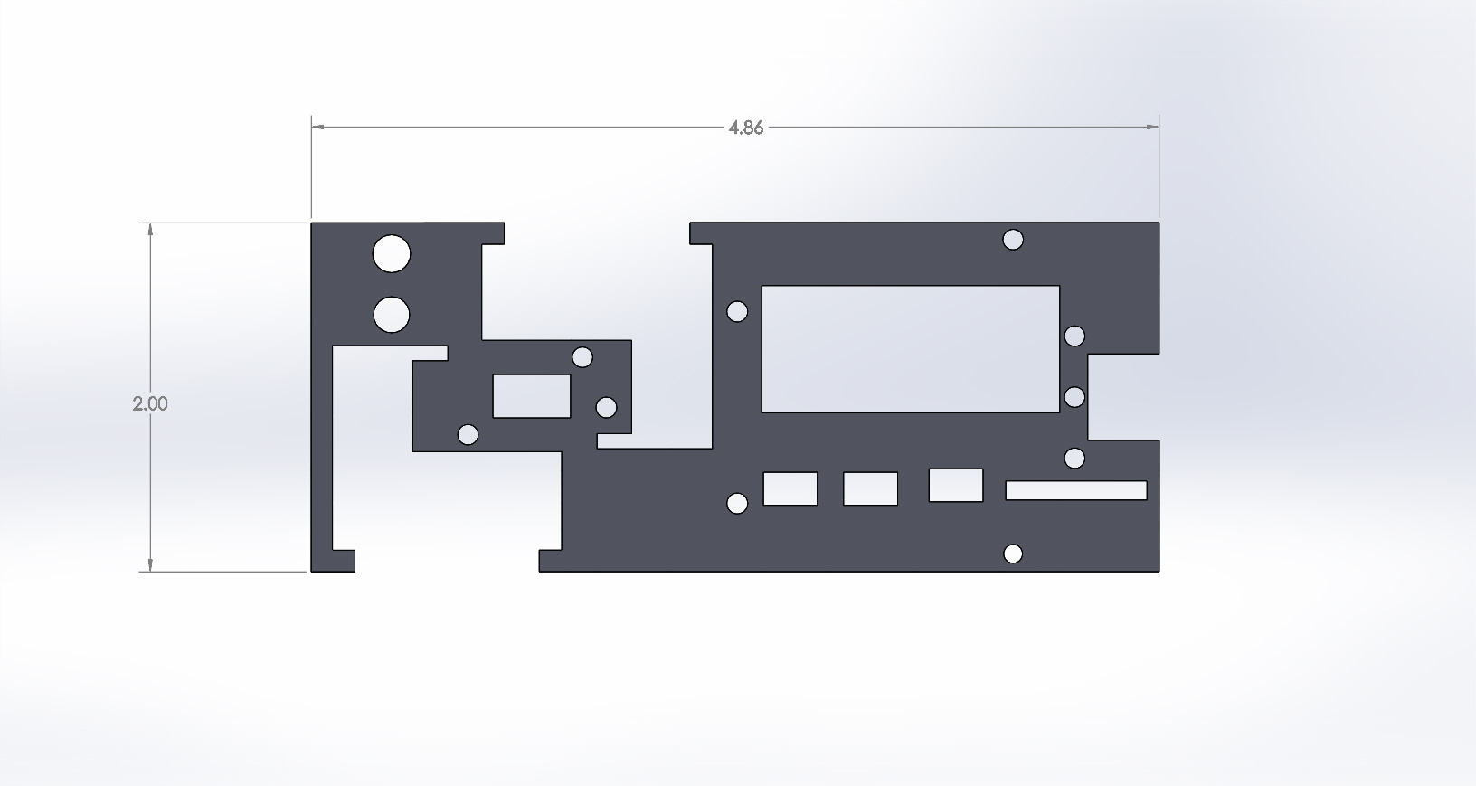
Figure 2: Top Panel
Front Axle
The front axle is composed of three major components: a front pivot axle, a connector from the front pivot axle to the wheel axle, and the wheel axle. Two different versions of the front pivot axle were initially rendered by the Design & Manufacturing Engineer for P-Bot, Railan. One of these two models was used for the front pivot axle after making the part thinner. After this modification was completed, the connector and wheel axle were modeled in SolidWorks from the given .stl file. All of these parts can be seen in the following figures.
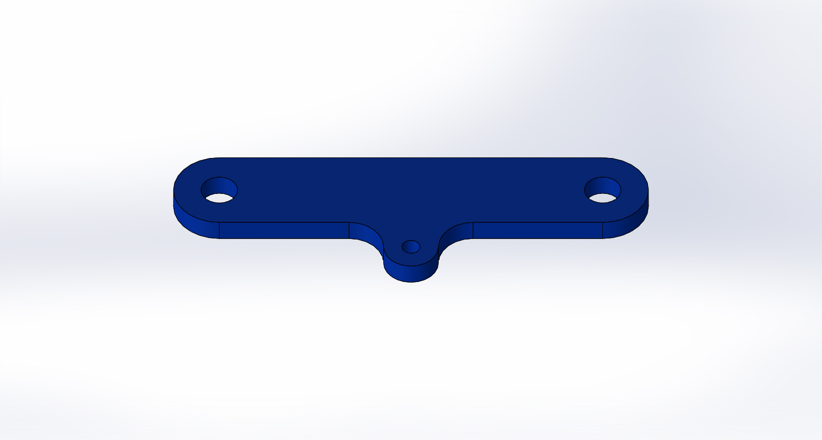
Figure 3: Front Pivot Axle
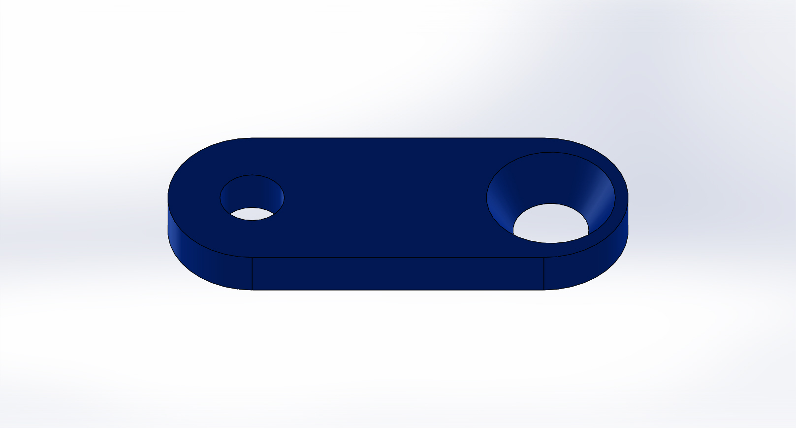
Figure 4: Front Pivot Axle to Wheel Axle Connector
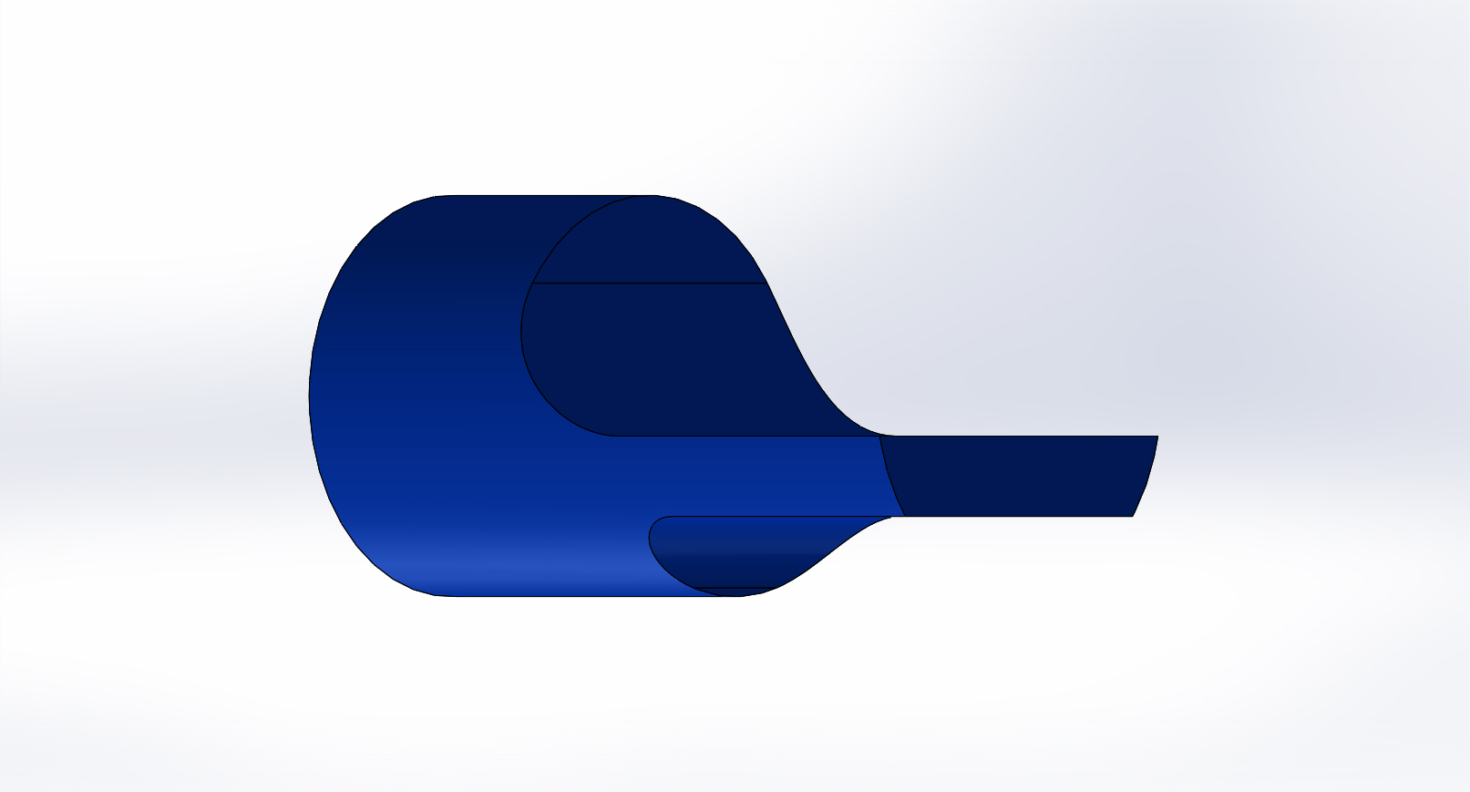
Figure 5: Wheel Axle
Servo Holder
Some additional modifications were made to the servo holder as well. The height of the holder was decreased and the motor heads on it were also made hollow. Hooks on one side of the holder were also added to place the wires of the proximity sensor in the front away from any moving parts. The modifications for this part of the design can be seen here:
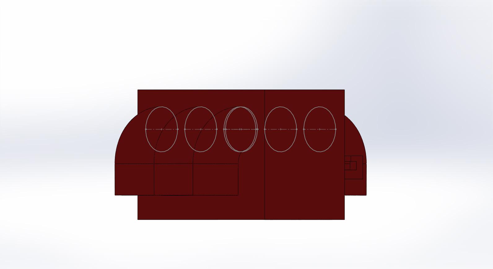
Figure 6: Servo Holder
Wheels
A minor change was made to the back wheels of the car. The hole where they are inserted into the GM6 motors were changed into D shaped to be able to be fit into the motor shaft. The changes can be seen in the following picture.
Tire treads were designed, modeled, and provided by Jeff Gomes.
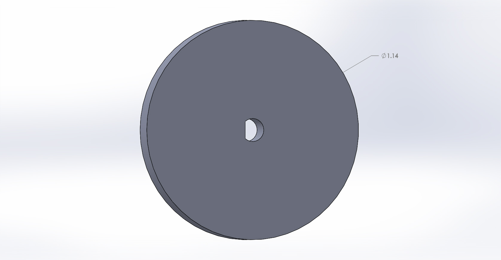
Figure 7: Wheel
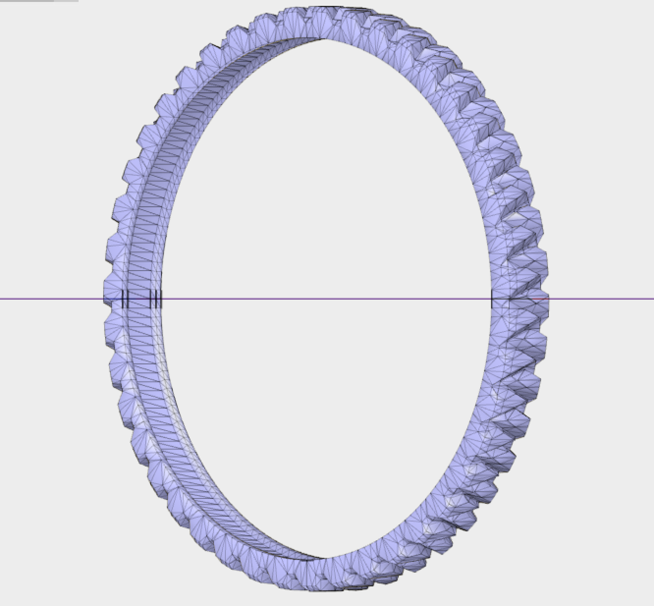
Figure 8: Wheel Tread (Designed, modeled, and provided by Jeff Gomes)
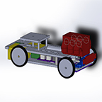
Full 3D Model
With all the changes and additions mentioned before, a new full 3-D model of our robot was assembled. The full model also includes the IR shield which was missing before. The 3-D model of the ModWheels car can seen be here.
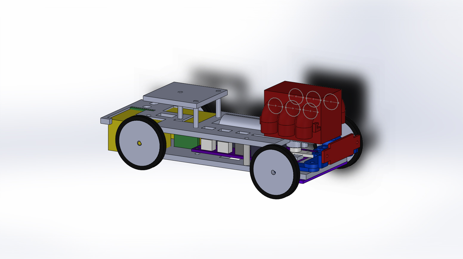
Figure 9: Full 3D Model