S17 Prosthetic Arm: Critical Program Module/Firmware
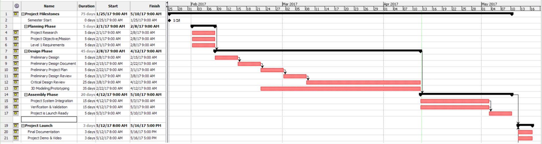
This shows the iterative design process that was used in the development of the code for the prosthetic arm.
This shows the iterative design process that was used in the development of the code for the prosthetic arm.
This is the working process of creating the firmware for the prosthetic hand, to control the motors and the servo in the hand with the flex sensors attached to the customer’s foot.
In order to control the Hand on this project, it needs two Printed Circuit Boards (PCB) to be wirelessly communicating to each other. One of the PCBs will be placed in the arm and the other in a containment box attached to the customers ankle that would have flex sensors attached on the inside of their shoe.
To satisfy L1.5 Custom PCB Requirement – The prosthetic arm shall implement a custom printed circuit board (PCB) that incorporates a complexity of design, implementing at least 2 layers, and includes the use surface mount components.
By Shaun Pasoz – Electronics & Control Engineer
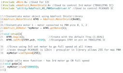
While waiting for the breakout boards to come in the mail, to make the best use of time the E&C division manager tasked us with coding quizzes. One of the quiz questions involved controlling the TB6612FNG motor driver using a microcontroller such as the Arduino UNO. Below is the snippet of code submitted for that quiz question along with the comments:
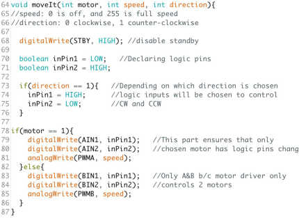
In order to allow easy calling of the functions for the MST engineer the moveIt() function was itemized into corresponding functions as follows: a forward move, backward move, left turn, and right turn. An example of the forward() function is demonstrated below:
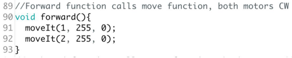
This code displayed above allows for control of two motors by utilizing four digital pins and two PWM pins from the microcontroller all from the same function. From here the next step was to include the code to control the third motor that will be controlling the winch.
Since the 3DoT only has pins available for two motors, it was necessary that the third motor be controlled via I2C. After doing some research it became evident that the Adafruit Motor Shield V2 used the same primary ICs as our PCB. To avoid writing code to manually control the I2C protocol the Adafruit Motor Shield library was used. The following snippets of code demonstrates our implementation of the Adafruit Motor Shield library:

To summarize, the motor shield object is instantiated using the Adafruit library with an address of 0x60. Motor 1 is then instantiated (since our project only needed one motor to be controlled only one instance of the object is instantiated), where the logic pins AIN1, AIN2 and PWMA from the TB6612FNG IC is connected to PWM pins 0, 1, and 2 on the PCA9685 chip. In order to allow for this the Adafruit library .cpp file was changed such that AFMS.getMotor(1) corresponds to PWM pins 0, 1, and 2.
The object is then began in the setup function and STBY pin on the TB6612FNG IC is brought HIGH by setting PWM pin 15 to a 100% duty cycle. Furthermore, the winch motor is set to full speed since the system utilizes 3.3V to power the motor, full speed is adequate for all instances of the winch motor control. Lastly, the equivalent move function of the winch motor is itemized in a function, called goUp(), to easily be called by the MST engineer when programming Bluetooth communication.
By Shaun Pasoz – Electronics & Control Engineer
Before sending out the PCB design for production, it is necessary to prototype the design using breakout boards and through-hole components. This is a necessary step to test the components in combination with the code and make sure the design works. The purpose of our PCB is to allow control of a third DC motor using the 3DoT. Our design utilizes two IC’s: the TB6612FNG manufactured by Toshiba, and the PCA9685 from NXP Semiconductors.
The TB6612FNG is a dual H-bridge motor driver. It will be used in our PCB design to control the third DC motor. The pins utilized on the motor driver will be VM, VCC, AIN1, AIN2, PWMA, STBY, AOUT1, and AOUT2. The PCA9685 is an I2C compatible 12-bit PWM driver. Since the 3DoT provides no PWM enabled digital pins, the component is necessary in the PCB design to provide PWM to the motor driver. The extraneous PWM pins will be used as a digital signal to control the motor driver.
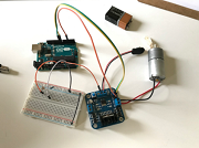
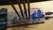
Seen below is a Fritzing diagram of our design alongside a picture of the actual implementation:
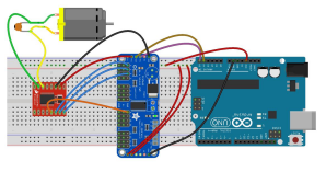
Figure 1: Breakout Board Fritzing Diagram
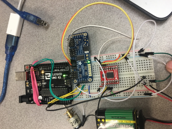
Figure 2: Image of Implementation of Breakout Boards
In an effort to avoid soldering and de-soldering leads to the breakout boards, the implementation is not as clean. The implementation also shows that the design can easily be powered from a separate power supply; in this case, a 9V battery.
Although the design works using breakout boards. When implemented on a PCB, the PCB did not work. This could be due to a couple reasons. One, it’s possible the IC’s got damaged in making the PCB as it was not built in an ESD safe lab. Two, it’s possible that there was a manufacturing error such as traces being placed too closely together, or traces poor insulation of the traces. The second choice is the suspected problem as we tried making three different boards, using new IC’s and testing both ceramic and tantalum capacitors.

Belinda Vivas (Project Manager)
Tyler Jones (Manufacturing)
Kevin Ruelas (Electronics)
By: Chastin Realubit (MST)
Table of Contents
By: Belinda Vivas (Project Manager)
The objective of the Second Generation of the Pick and Place is to:
❖Build up from the First Generation of the Pick and Place machine and create an user friendly design.
❖Create a user friendly manual:
❖It shall be built in stages.
❖Make the Pick and Place consistent with the manufacturer of only a few boards per semester.
By: Belinda Vivas
The mission plan for the Second Generation Pick and Place is to place all components used for the 3Dot Board 4.54 faster than a person. Manufacturing time of a person is 4 hours, so anything less than that is acceptable, with 1 hour being the target time.
The overall goal of this project is to have a working Pick and Place machine for future EE400D students to build their custom PCB. The 3Dot Board that will be constructed is more difficult than any PCB students will make, therefore, this machine can theoretically make any board future students plan to do.
Because this machine is supposed to be used by students, we will include manuals (written and video) so that future generations can operate this machine with ease. We will conduct experiments using Electrical Engineering students to see if they can operate the machine using only the given manuals.
The overall summary for the Mission Profile is:
❖To create a 3-Dot 4_54 PC Board.
❖Ensure precision and calibration through the addition of a camera system (Edge Detection).
❖Create a CSV file to implement a better interface between the user and the machine.
❖Multiple feeder assemblies
❖Incorporate better materials
❖Tape feeder for the following component parts:
By: Belinda Vivas (Project Manager)

Figure 1 – Detailed Design of Generation 2
Electronics:
❖Camera System
❖Two Arduinos System
❖Vacuum System
❖Servos System
❖Power Emergency Switch
Manufacturing:
❖Higher legs with rubber on the base to provide better stability due that more weight is being added causing for higher vibration.
❖Higher amount of component feeders.
❖IC Chip component holder
❖Power Switch
❖Camera
❖Component Cabinet
❖Electronics Cabinet
❖Tape waste bin
By: Chastin Realubit (MST)

Figure 2 – System Block Diagram
By: Tyler Jones (Manufacturing)
The vacuum by itself was powerful enough to carry the Atmega chip but experiments show that we need a bigger nozzle to increase airflow.

Figure 3 – Solenoid Circuit
Blog Post: https://www.arxterra.com/pick-and-place-solenoid-valve-design-and-control-2/
By: Chastin Realubit (MST)
Z-Axis Motor: We did an experiment to see the load that the Z-Axis can handle and we found that it will still carry up to 2000 g. This experiment was done so that we can see if the motor can still move up and down even with more load. This was needed because we are adding a camera on the Z-Axis and we needed the system to still function with extra weight.

Figure 4 – Nozzle System
Blog Post: https://www.arxterra.com/pick-and-place-z-axis-and-nozzle-test/
By: Tyler Jones (Manufacturing)
-The machine has a basic feature of rubber shoes for legs of the platform stand.
-This will aid in damping vibrational disturbances.
-A 4” x 4” x 1” block of butyl rubber shaped using a bandsaw and miter saw.
-The block was fitted to form shoes that fit over the legs of the machine.
-The blocks have been tested on one leg for stability.
-The use of a milling router machine should be used

Emergency Power Switch: https://www.arxterra.com/pick-and-place-emergency-power-switch/
By: Tyler Jones (Manufacturing)
3Dot IC Tray:https://www.arxterra.com/pick-and-place-3dot-ic-tray/
By: Tyler Jones (Manufacturing)
12 Servo Mount & Tape Feeder System:https://www.arxterra.com/pick-and-place-12-servo-mount-tape-feeder-system/
By: Tyler Jones (Manufacturing) and Belinda Vivas (Project Manager)
Camera Test: https://www.arxterra.com/pick-and-place-camera-test/
By: Kevin Ruelas (Electronics)
Solenoid Valve Design and Control:
By: Tyler Jones (Manufacturing) and Kevin Ruelas (Electronics)
Servo Driver: https://www.arxterra.com/pick-and-place-servo-driver/
By: Kevin Ruelas (Electronics)
Camera System: https://www.arxterra.com/pick-and-place-trade-off-study-camera-system/
By: Kevin Ruelas (Electronics)
By: Kevin Ruelas (Electronics)
Though the user can type commands manually in the GRemote, once the machine is running and calibrated, use command G28 to set the origin then send the CNC file and wait for the machine to do the rest.

Figure 7 – GRemote controller

Figure 8 – GCode Commands
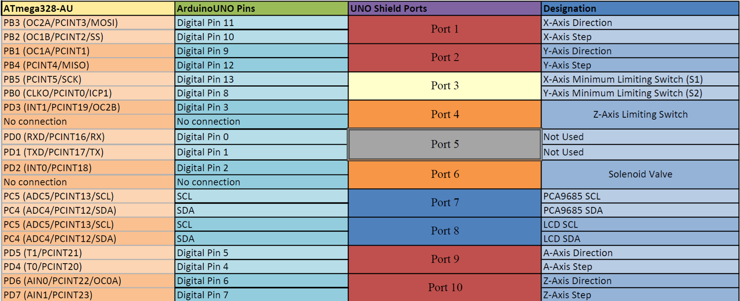
Figure 9 – Arduino 1 Interface Definitions
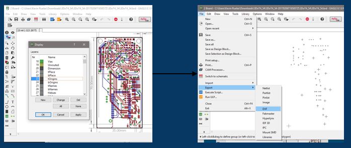
Figure 10 – Eagle CAD to Pick and Place
By: Kevin Ruelas (Electronics)
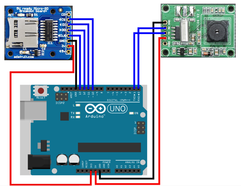
Figure 11 – Camera Fritzing Diagram
By: Kevin Ruelas (Electronics)
Since the 1st Gen. already defined the origin, the edge detection of a “target” will be used to calibrate this location and prompt the user to make this correction via GRemote.
By: Kevin Ruelas (Electronics)
The overall Pick and Place was composed of various subsystems which were all ran by a common code. The motors, the nozzle, calibration, camera, LCD display, servo driver, and solenoid.

Figure 12 – High Level Software
Blog Post: https://drive.google.com/open?id=0B9iWYCBTJWEEeEFxc1pjU0ZFTjQ
By: Tyler Jones (Manufacturing)
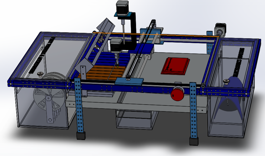
Figure 13 – Side View of SolidWork Design

Figure 14 – SolidWorks Top View Design
By: Chastin Realubit (MST)
The purpose of this section is to provide a comprehensive Verification and Validation (V&V) Test Plan of the Spring 2017 Pick and Place including the Project ConOps/Mission, Test Methodology, Verification and Validation Matricies, Test Cases, and Exit Criteria.
https://drive.google.com/open?id=0B9iWYCBTJWEEU05NMy1SMUs2ajQ
By: Chastin Realubit (MST)
| Components | Expected Current Draw (A) | Uncertainty (%) | Margin (±A) | Measured Current Draw(A) | |
| Stepper Motor (X-Axis) | 1.35 | 5% | .0675 | .44 | |
| Stepper Motor (Y-Axis) | 1.35 | 5% | .0675 | .44 | |
| Stepper Motor (Z-Axis) | 1.35 | 5% | .0675 | 2.83 | |
| Stepper Motor (A-Axis) | 1.35 | 5% | .0675 | .44 | |
| Detection Camera | .75 | 5% | .0375 | TBA | |
| Solenoid Valve | .40 | 5% | .02 | .42 | |
| Display Screen | .75 | 5% | .0375 | TBA | |
| Servo fs90r (12) | .2 | 5% | .01 | .21 | |
| Project Allocation | 6 A (Calculated knowing that we will be using two Arduinos with separate power supplies) | ||||
| Total Expected Current | 3.45 A (The motors and servos will not run simultaneously) | ||||
| Total Margin | .375 A | ||||
| Contingency | 2.175 A | ||||
By: Chastin Realubit (MST)
| Vacuum System Components | Preliminary Mass (g) | Uncertainty (%) | Margin (±g) | Expected Mass (g) | Actual Mass (g) |
| Stepper Motor (A-Axis) | 245.00 | 5% | 12.25 | 245.00 | 247 |
| Stepper Motor (Z-Axis) | 245.00 | 5% | 12.25 | 245.00 | 246 |
| Vacuum Nozzle | 2 | 5% | .1 | 2 | TBA |
| Z-Axis Actuator | 292.00 | 5% | 14.6 | 300 | 244.12 |
| Detection Camera | 3 | 5% | .15 | 3 | TBA |
| Project Allocation | .Preliminary allocation is 2000g | ||||
| Total Expected Mass | 795 g | ||||
| Total Margin | 39.35 g | ||||
| Total Actual Mass | TBA | ||||
| Contingency | 1165.65 g | ||||
By: Belinda Vivas (Project Manager)
For the Second Generation of the Pick and Place, our allotted project budget was of $500, in which a total of $469.04 was spent; it was divided as follow:
| Receipt | Vendor | Item | Unit | Quantity | Total Cost (Including Shipping) | Purchased By |
| 1 | Makeblock | RJ25 Adapter | $4.98 | 1 | $15.65 | Kevin Ruelas |
| RJ25 cable-20cm (4-pack) | 1 | |||||
| 2 | Amazon | 12 Bit PWM Servo Driver | $11.99 | 1 | $11.99 | Kevin Ruelas |
| 3 | Amazon | Blue Backlight LCD Module | $7.99 | 1 | $7.99 | Kevin Ruelas |
| 4 | Amazon | 3-Pin Extension Lead Wire | $6.99 | 1 | $6.99 | Kevin Ruelas |
| 5 | Amazon | Arduino Power Supply Adapter | $6.29 | 1 | $6.29 | Kevin Ruelas |
| 6 | Amazon | 120 pcs Dupont Wire | $8.86 | 1 | $8.86 | Kevin Ruelas |
| 7 | This item was removed. Arduino Uno will not be needed for the project anymore and the student requested to keep the board. | |||||
| 8 | AdaFruit | MicroSD Card | $7.50 | 1 | $52.56 | Kevin Ruelas |
| JPEG Camera | $35.95 | 1 | ||||
| 9 | Pololu | Rotation Servo | $4.95 | 9 | $49.50 | Chastin Realubit |
| 10 | GearBest | LCD Display Screen | $4.53 | 1 | $17.18 | Chastin Realubit |
| 11 | Amazon | PWM Servo Driver | $11.99 | 1 | $15.98 | Chastin Realubit |
| 12 | Ebay | Rubber Bench Block | $7.48 | 1 | $7.48 | Tyler Jones |
| 13 | Sewvac LTD | Bobbins for Servos | $3.29 | 1 | $3.29 | Tyler Jones |
| 14 | RadioShack | Mosfet IRF 510 | $1.78 | 1 | $1.78 | Tyler Jones |
| 15 | ACE Hardware | Nuts & Bolts | $5.40 | 1 | $5.93 | Tyler Jones |
| 16 | The Home Depot | Wood | $29.98 | 1 | $29.98 | Tyler Jones |
| 17 | The Home Depot | Aluminum Plates & Epoxy | $35.68 | 1 | $38.45 | Tyler Jones |
| 18 | MicroCenter | 3D Printer Filament | $14.99 | 1 | $16.15 | Tyler Jones |
| 19 | The Home Depot | Screws | $18.49 | 1 | $18.49 | Tyler Jones |
| 20 | The Home Depot | Plastic Sheet | $140.06 | 1 | $140.06 | Tyler Jones |
| 21 | ACE Hardware | Screws | $14.44 | 1 | $14.44 | Tyler Jones |
| Total: | $469.04 | |||||
| Name of Individual | Position | Total Amount Reimbursed |
| Kevin Ruelas | Electronics | $110.33 |
| Chastin Realubit | MST | $82.66 |
| Tyler Jones | Manufacturing | $276.05 |
| Total** | $469.04 |
By: Belinda Vivas (Project Manager)
By: Belinda Vivas (Project Manager)

By: Belinda Vivas (Project Manager) and Tyler Jones (Manufacturing)
We were able to incorporate more extensive and higher technology subsystems into the Second Generation of the Pick and Place; by implementing a more user friendlier systems and introducing a camera system, LCD Display system, redesign of the nozzle, better calibration system, higher servo driver system, and an overall new manufacturing design.
The pick and place was successful in picking and placing parts onto the 3DoT board. The machine when calibrated can place parts into the respective locations where they can be soldered using the IR reflow machine. It is important however to note that the pick and place machine can be improved in the following areas. Its mechanical, and electronic design can be updated with simple solutions that require more time. They are discussed below.
The pick and place mechanical design can be improved in a noticeable and easily recognizable ways with more time for development. The first is the belt system.
1) The belt system does work well, and the X and Y stepper motors move to positions accurately, sometimes during design of the machine the tensioner plates that hold the 3 belts into place were loosened. This is so that parts in the machine can be easily worked on. Therefore it is important to make sure that belts are tight, as well as lubricated. Loose belts cause the machine to make a noticeable sound that is not as fluid as when they are tight. The best solution would be to incorporate threaded drives instead of belts, however this is more costly.
2) The pick and place uses a 3DoT board that was 3D printed with more than 6 iterations. This was due to numerous errors in the printing temperature, malfunction, and design limitations. There is a table that corresponds to part sizes and dimensions and adjustments made to account for error of the 3D print. It is found here, 3DoT IC Tray. A decent 3D printer and filament must be used in order to get the precise dimensions necessary. An alternative solution would be to cut a small rectangular piece of plastic that is about 0.5-0.75 inches thick, and have it precisely laser cut. The laser cutter used in the design center was not accessible in this generation later on in the project timeline.
3) The Z-axis is supported by two aluminium slider rods. These slider rods must be spaced as far apart as possible so that the heavier Z-Axis can have a wider more stable base and center of gravity. This design was used in the pick and place and must be incorporated if further design iterations will be made. The camera is mounted on a bracket that allows makes it so that the Z-Axis only can be bolted to two of the aluminium sliders. This must be made able to be bolted into all four of the sliders. It is shown below

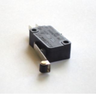
4) The pick and place currently uses a locked position origin. This is so that the the machine can be turned off and moved back to the locked position manually. From here the pick and place machine can be moved to the function “L” bracket origin. It would be a much safer design if limit switch can be placed on the X and Y axis so that if the user were to accidentally enter the wrong code in the machine the motors would not grind. This can be accomplished by using the current limit switches and adding the limit switch code to the stepper motor.ino Arduino code. The limit switch acts as an electromechanical disconnect that simply switches off the stepper motors when the machine makes contact with the switches. An image of the switch is shown below.
5) The electronic design can be further enhanced if the 12 channel servo driver can be made to separate the digital power source which carries Arduino logic level signals of +3.7V and +5.0V, and the analog power source which carries +12V signals. The connection is made through the Me Uno RJ25 board. This connects an an RJ 25 communications signal with a 12 V analog signal.
6) The edge detection camera code was functional and the code calculated the position of the origin by comparing picture taken by the camera, and comparing the pixel lengths. The edge detection however was off by about 0.3 which is about 1mm in actual length. In order to improve the accuracy of the machine a higher resolution camera must be used.
Video – https://www.youtube.com/watch?v=2Cn5abf5Arw
Preliminary Design Document – https://www.arxterra.com/pick-and-place-preliminary-design-document/
Preliminary Project Plan – https://www.arxterra.com/pick-and-place-preliminary-project-plan/
PDR: https://drive.google.com/open?id=0B9iWYCBTJWEES1g1emo3NklpTmc
CDR: https://drive.google.com/open?id=1tGSSGGry0n6I4EDJ9IYzM1PXZUMOc_jJTCyYj9YSV1E
Blog Posts: https://drive.google.com/open?id=0B0hJ_mPvve6CRVpqOU1mdUN2aFk
Code Files: https://drive.google.com/open?id=0B0hJ_mPvve6CY0t5SjNuWk1OOEk
3Dot BOM: https://drive.google.com/open?id=1rC5BPWV3KqwXsGQ3CgFeVNoKTumOvdZjCftwd7t0eEU
Servos BOM: https://drive.google.com/open?id=0B7gruONfGRYcUExJeVBxMzNYblU
GCode Commands: https://drive.google.com/open?id=1CKODeCrm8FpmgrmSp363mjAMPNYaCCe5904dLSit4cs
3Dot 3D print File: https://drive.google.com/open?id=0B0hJ_mPvve6CNXVTQVNyVGxCT3c
3Dot Board: https://drive.google.com/open?id=0B0hJ_mPvve6CN25OSU01aEcwWlE
https://drive.google.com/open?id=0B0hJ_mPvve6CN2dIZHZXTzAtSWs
Ace Converter: https://drive.google.com/open?id=0B0hJ_mPvve6CTlI1NzNHX1BTLTQ
Arduino: https://drive.google.com/open?id=0B0hJ_mPvve6Ca1BpM3FGNDYzWVE
GCode: https://drive.google.com/open?id=0B0hJ_mPvve6CM2pNZ2hCWl9ZMXc
Me Uno Shield: https://drive.google.com/open?id=0B0hJ_mPvve6CUmtDcEN5LUxQSjg
Meeting Minutes: https://drive.google.com/open?id=0B0hJ_mPvve6CNXRhRFd5RThkR1k
Research: https://drive.google.com/open?id=0B0hJ_mPvve6CeS1tQmFRQ3hqQ3c
SolidWorks Files: https://drive.google.com/open?id=0B0hJ_mPvve6CaFVoR1RaRl93bkE
XY-Plotter: https://drive.google.com/open?id=0B0hJ_mPvve6CckVuWkJvOU53eEE
All Files: https://drive.google.com/open?id=0B0hJ_mPvve6CNXVTQVNyVGxCT3c
Instructional Manual: https://drive.google.com/open?id=1eXx-_8FduTJi8nRR356R3nj0DHnTqq50er3VYreTGXA
Project Libre Schedule: https://drive.google.com/open?id=0B9iWYCBTJWEET2pLMHVJVVd2am8
Verification and Validation: https://drive.google.com/open?id=0B9iWYCBTJWEEU05NMy1SMUs2ajQ
By: John Her (Project Manager)
Moses Holley (Electronics and Control)
Edgardo Villalobos (Manufacturing-Solar Panel)
Johnathan Chan (Manufacturing-Chassis)
Adan Rodriguez (Mission, Systems, and Test)
Table of Contents
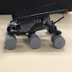
The Mini Pathfinder project for Spring 2017 is a scaled and modeled after NASA’s 1997 Sojourner rover of the Pathfinder mission. It will utilize the 3Dot board and a custom PCB. It is to be remotely operable with a fully functioning rocker bogie suspension system. It will be able to provide speed and battery telemetry to the user via the arxterra app and have a solar panel that charges the battery.
Our mission is a scaled version of the Pathfinder project. We will remotely traverse a course of 27.8 meters in length. The course will have 3 stairs it will descend and 3 stairs it will ascend with each stair being 27mm. During this course the Mini Pathfinder will demonstrate electronic differential turning, solar charging, proper rocker bogie mechanics and provide telemetry.
The Mini Pathfinder will use the 3Dot and a custom PCB for the extra motors and the encoders.
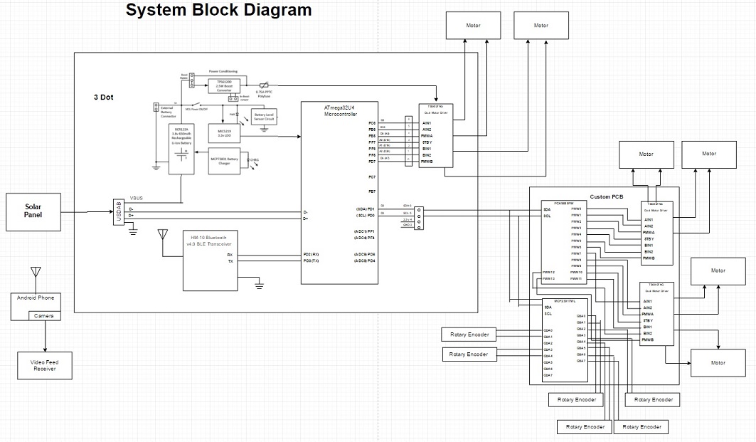
Figure 1. System Block Diagram
We have three interface definitions for three different IC’s. The first is for the 3Dot board. The next two are for the custom PCB that will have the two extra motor drivers and the digital io expander for the rotary encoders.
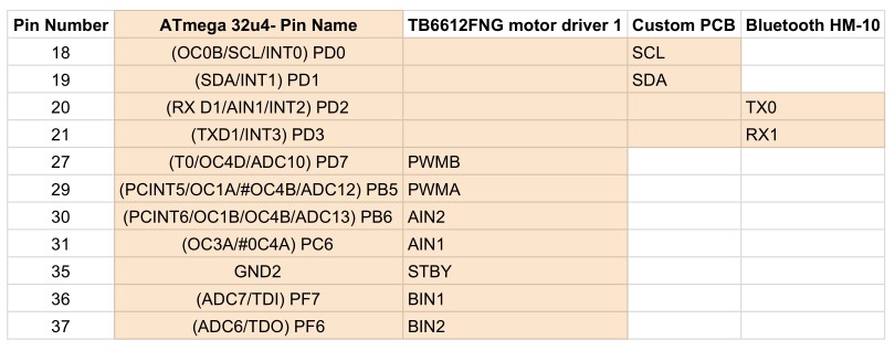
Figure 2. Interface Definitions for the 3Dot Board
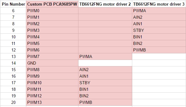
Figure 3. Custom PCB IC Motor Driver Interface Definitions
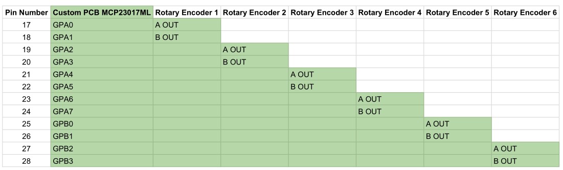
Figure 4. Custom PCB IC Rotary Encoders Interface Definitions
Our cables will be routed from the motors and encoders through the suspension and into the electronics box. The solar panel will have a mount with a hole where the cable will connect so that it can charge the battery.
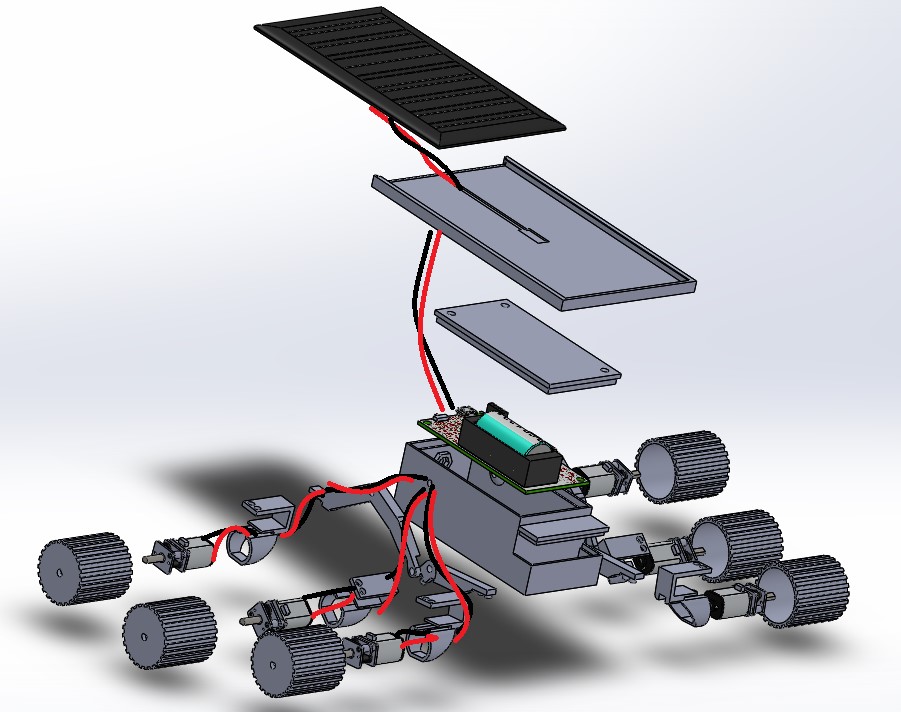
Figure 5. Cable Tree
Figure 6.
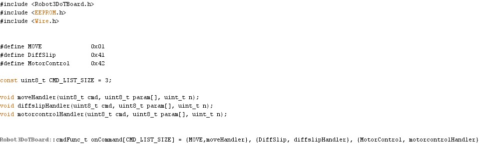
Figure 7.
After the trade off studies, we have decided on micro metal gear motors and hall effect sensor based rotary encoders. To control the extra motors not connected directly to the 3Dot, we will be using a custom PCB that is base on the adafruit motorshield which houses a PCA9685 and two TB6612FNG motor drivers. In addition to the motorshield, we will also implement a MCP2301 I/O expander to take the digital input from the rotary encoders. The power for the extra motors will be supplied from the battery boost on the back of the 3Dot board so that we can access the same voltage that is supplied to the motors on board the 3Dot.
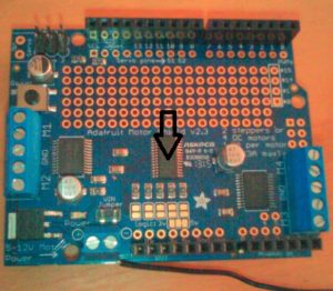
Figure 8. Adafruit Motorshield (PCA9685)
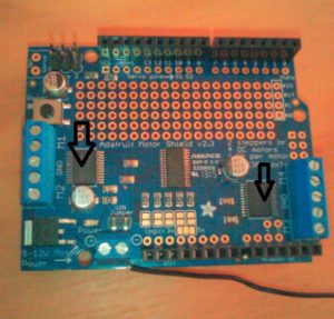
Figure 9. Adafruit Motorshield (TB6612FNG)
After discussing our project flow chart with an fellow Electronics and Control Engineer, Forest Nutter, we decided to redesign our flow chart. The initial image is the beginning stages of an overall view of the project.
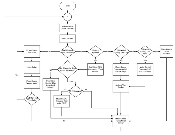
Figure 10. Firmware Flowchart
Since the 3DoT only has a single motor driver chip that is capable of driving two motors, we needed to make a custom PCB to interface with the 3DoT that will allow for 4 additional motors and also be able to take digital input for the rotary encoders. We modeled the motor driver off of the adafruit motor shield version 2.3. The motor shield consisted of the PCA9685pw PWM driver and two TB6612FNG dual motor drivers, which is what the 3DoT uses. The PCA9685pw allows for control of PWM outputs through the I2C bus, which is available through the 3DoT, so that we could properly control the motor drivers. For the digital IO expander, we chose the MCP23017 due to it having 16 digital IO channels for our rotary encoders, which use two digital outputs per wheel for a total of 12 outputs.
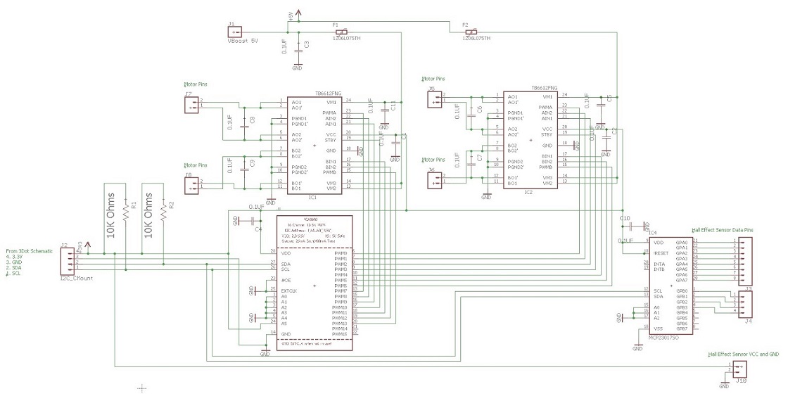
Figure 11. Custom PCB Schematic
Our first schematic design had many errors that were easy to point out and a few that were only seen if looking very close. Fabian, previous EE 400D student, pointed out the schematic flaws and gave recommendations. One of the mistakes I made was in forgetting the pull up resistors for the I2C communication. The I2C needs the pull up resistors because most of the devices are active low. Throughout my ICs and the voltage in, (VCC and VBoost), I forgot to place decoupling capacitors for circuit protection and for clean signals. My first completed schematic looked great with labels on the wires. By simply clicking the name of the wire and looking closely, I connected the TB6612FNG dual motor driver outputs to each other which caused them to short. My project manager, Jon Her, advised that we start from scratch. After the irritative process the above image is the finish schematic. It was a tough process, but having the schematic looked over and over ensured that we have a potential working PCB.
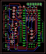
After the electronics and controls engineer(ENC), was finished with the schematic on EagleCAD, it was suggested that we try to make a printed circuit board(PCB) out of it and mount the PCB onto the 3DoT board like a “shield” because it was a level 2 requirement(See Figure 1). On the EagleCAD, requirements for the power lines had the size of 16mil. Data routes had 10mil. And there was a 20 drill size for vias. All of the lines had a 45 degree turn so that it doesn’t lose its connection when it is printed and powered up. The top and bottom planes of our PCB are ground copper poured planes. After placing all of the parts on the specified size of the layout, we made sure we used the DRC several times to make sure it completed all the requirements. We also ordered the parts and components before the PCB was made, so that it would arrive in a timely manner.
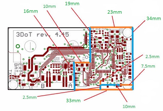
Figure 12. Dimensions of the Custom PCB Shield
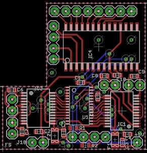
Figure 13. Screenshot of the Routing Diagram
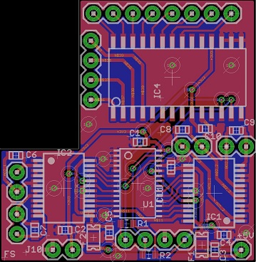
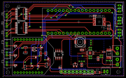
Figure 14. Final product with top and bottom ground copper poured planes in red and blue
We created a custom PCB for our 3Dot board(see figure 3). After we did a final DRC on our final PCB, we then sent it to the president, customer, and Fabian for approval. We had to revise our board several times before it was approved, but once it was, it was sent to 4PCB to be manufactured. We then purchased the stencil from OshStecil. The next steps are to use the stencil and put solder paste on the top layer of the custom PCB. Then we will put the parts and components in its respective places. After, we will heat the board up using a heat gun so that the components will attach onto the board.
To ensure that the 3Dot sat correctly into the chassis, small cutouts were made to allow the Bluetooth module room along with a few pins that were sticking out from the battery holder. A channel was also cut out to allow a wire to access the battery boost on the underside of the 3Dot. There were also channels cut out to allow access to the usb port and the power switch on the 3Dot.
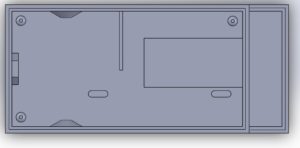
Figure 15. Inside the chassis
To allow proper rocker bogie mechanics, a three beveled gearbox was utilized. Each gear has 16 teeth to allow for a 1:1 gear ratio from the left side of the suspension to the right side.
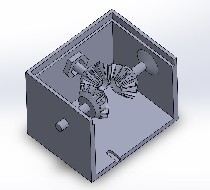
Figure 16. The rocker bogie gearbox
As a requirement, the Mini Pathfinder was to have a Solar Panel charge the battery on the 3dot board. To accomplish this, the solar panel needed to be scaled to the rover, while also being able to supply enough voltage and current. The solar cells also needed to be encapsulated. The model of the solar panel was closely modeled after the Sojourner Rover.

Figure 17. Solar Cell on the Mini Pathfinder
With the help of the chassis manufacturer for the mini pathfinder, we were able to scale the size in which the solar panel needed to be. The model was scaled using schematic renderings of the real Sojourner that were found on the internet. The size of the solar cell needed to be around 122x52mm.
Once the size of the panel was found, I needed to find solar cells that were able to charge the 3dot battery and that would fit that size and then encapsulate them. To meet this, I used a 5V 200mA already encapsulated cell that was bought in store. The size of the solar cell was 120x70mm, which fit the requirement of size.
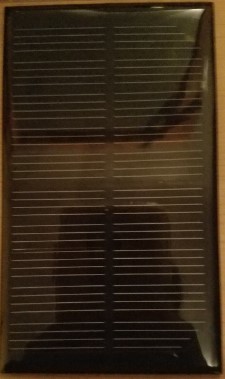
Figure 18. 120x70mm 5v 200mA Encapsulated Solar Cell
A micro usb was attached to both the positive and negative leads of the solar panel.
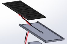
Figure 19. Wiring Diagram
After finding the type of solar cell I’d be using, a way of holding the cell onto the rover needed to be found. Using Solidworks, I was able to create a holder to house the cell in place with a hole in the bottom to allow for the micro usb plug to pass through to connect to the 3dot board through the outside. This holder allowed for easy replacement of the cell, if needed. The cell could easily be removed by sliding in and out.
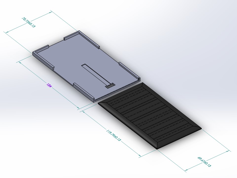
Figure 20. Solar Cell Holder
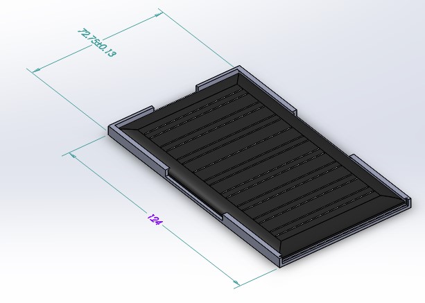
Figure 21. Solar Cell in Holder
In conclusion, the solar cell needed to be tested more in order to observe how long it really took to charge the battery. Overall the solar cell was a success in looks and functionality as far as charging.
Verification and validation can be viewed at this link.
https://drive.google.com/open?id=1D4-kNlP_zy35XqHd-88Zd2Wl2X3w6gr05WJnChsNDzU
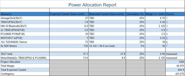
Figure 22. Power Allocation based on maximum battery current discharge at any given time.
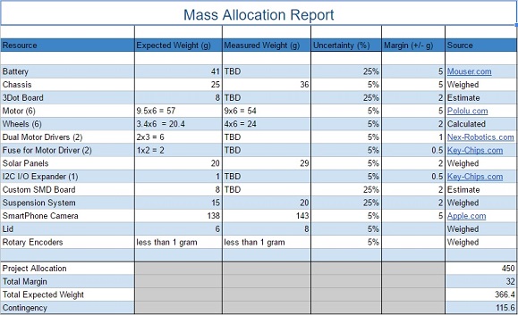
Figure 22. Mass allocation
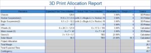
Figure 23. 3d Print time allocation
While we were able to get many parts and pieces for free, what cost the most was the custom PCB parts and the rotary encoders.
Figure 24. Costs of the project
With all our tasks still left to finish and the progress we made on the project. We finished at %62 completion and remained behind schedule.

Figure 25. Project Burndown with completion at 62%
If there is anything I would change knowing what I know now, it would to ensure that progress is made consistently every week and that the project schedule be updated at every opportunity. Meeting up with Professor Hill is always a good idea as well. He has valuable input, and tries to help. The lectures may not cover everything but that is why there is so much documentation on Professor Hill’s website. I would also suggest reading over all the material and not taking any other classes that require a lot of time, as this class will already eat up all your time.
Project Video: https://youtu.be/HVbv6seOrCA
CDR:https://drive.google.com/open?id=1jm68b_I-lYIxEX2KnLQ9umSzJKdmA3KJs0HE2ciRDsY
PDR:https://drive.google.com/open?id=1ROLFfi2FNQnKXeBWZFecfNi36JnrB8bCFhlLQb2EYzE
Project Libre:https://drive.google.com/open?id=0BwLPwnTqIptrcWEwalpwLS1oVzA
Burndown:https://drive.google.com/open?id=0BwLPwnTqIptrWHE0c3lnbHEtYnM
Verification and Validation:https://drive.google.com/open?id=1D4-kNlP_zy35XqHd-88Zd2Wl2X3w6gr05WJnChsNDzU
Solidworks:https://drive.google.com/open?id=0BwLPwnTqIptremdfTTRaNkY5bFE
Fritzing Files: https://drive.google.com/open?id=0BwLPwnTqIptrc2xkWm5tYVdiM0U
EagleCAD:https://drive.google.com/open?id=0BwLPwnTqIptrM1pZbllodXVnbnM
Arduino Firmware: https://drive.google.com/open?id=0BwLPwnTqIptrQldiNFI1cDg3cW8
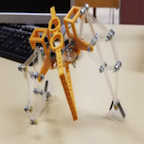
Table of Contents
By: Jesus Enriquez (Project Manager)
Spring 2017 Velociraptor Project Team:
Jesus Enriquez (Project Manager)
Oscar Ramirez (Mission, Systems, & Test)
Mohammar Mairena (Electronics & Control)
Andrea Lamore (Manufacturing)
The Objective of the EE 400D Velociraptor Robot is to produce a robot that emulates the body of a “Velociraptor”. The robot will compete in a custom game of “Pac-man”. The finished product must meet the following Program and Project Requirements:
The Velociraptor Robot shall compete in a “Pac-Man” style game against the Biped Robot during the EE 400D Final on May 15th, 2017 as described below:
Below is an exploded view of the system design for our Velociraptor.
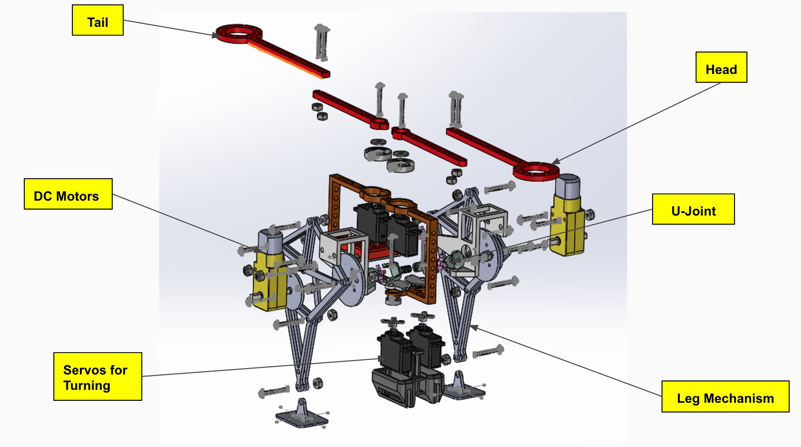
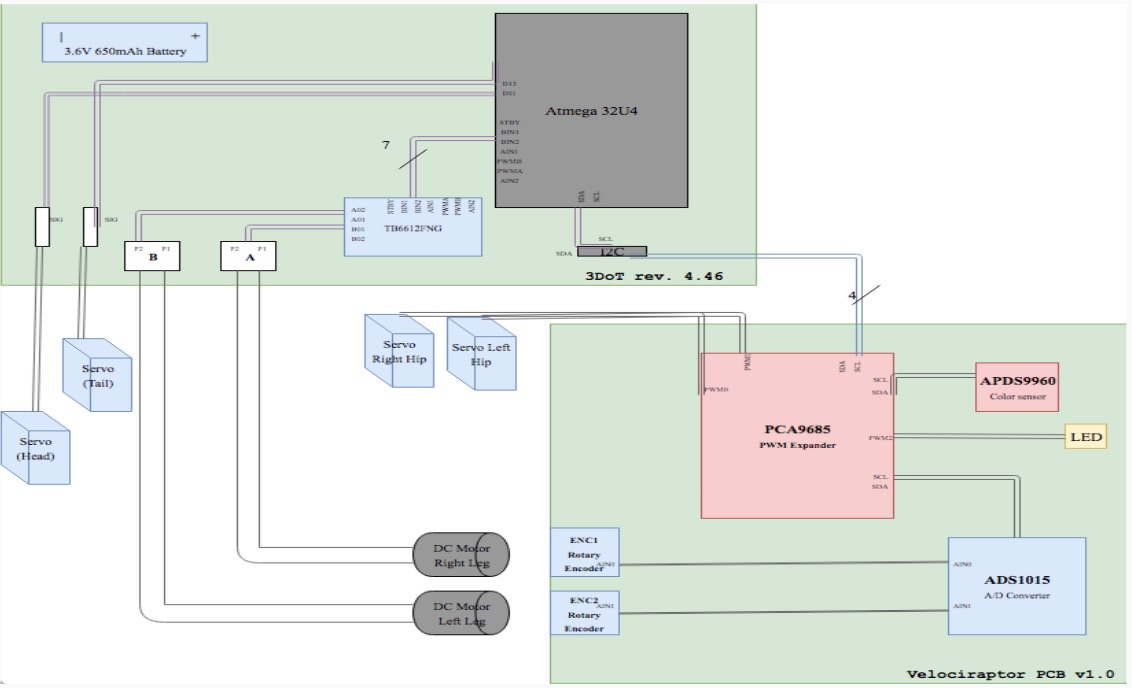
The system Block Diagram shows the inputs and outputs of our Velociraptor. It shows that our original design had a total of 4 servos and 2 DC motors, along with 2 rotary encoders for determining the velociraptor’s leg position. Ultimately this design was changed over and over as we went through the iterative design process. We ended up using only 2 DC motor and 2 servos, along with 1 rotary encoder to determine the position of the legs.
We were able to test out and experiment on most of the driving factors of our robot. The following tests/experiments have been documented in blog posts with further information which can be reference to below.
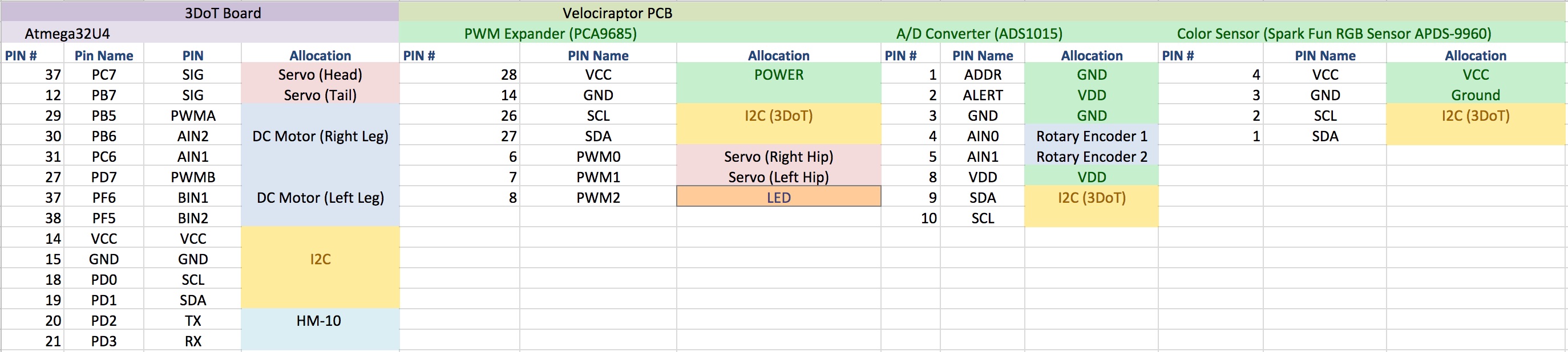
In the figure below, is the interface definition matrix for our robot. It is important to keep this interface matrix updated and to also continuously keep track of all the revisions because as the design changes, it can have an affect on the resources that have been allocated in the previous design such as number of pins and hardware limitations. It might be a good idea to leave room on your custom PCB or Schematic in the case that the design changes and you need more pins available for a variety of thing (i.e. extra motors, new sensors).
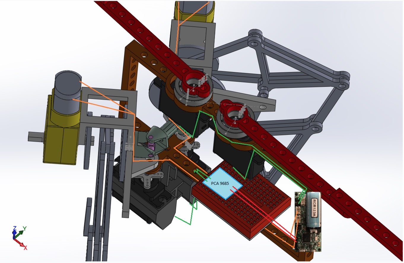
Our Cable Tree was done through computed aided drawing which is not recommended. But as you can see below, we took into account the different things that would need to be mounted onto our robot like the 3DoT, the PCB, and the motors. One of the things we did not take into consideration was the slack that we would have to allow for the wires when turning the legs. Also, wire wrap is highly recommended to use in order to give the robot a cleaner overall look.
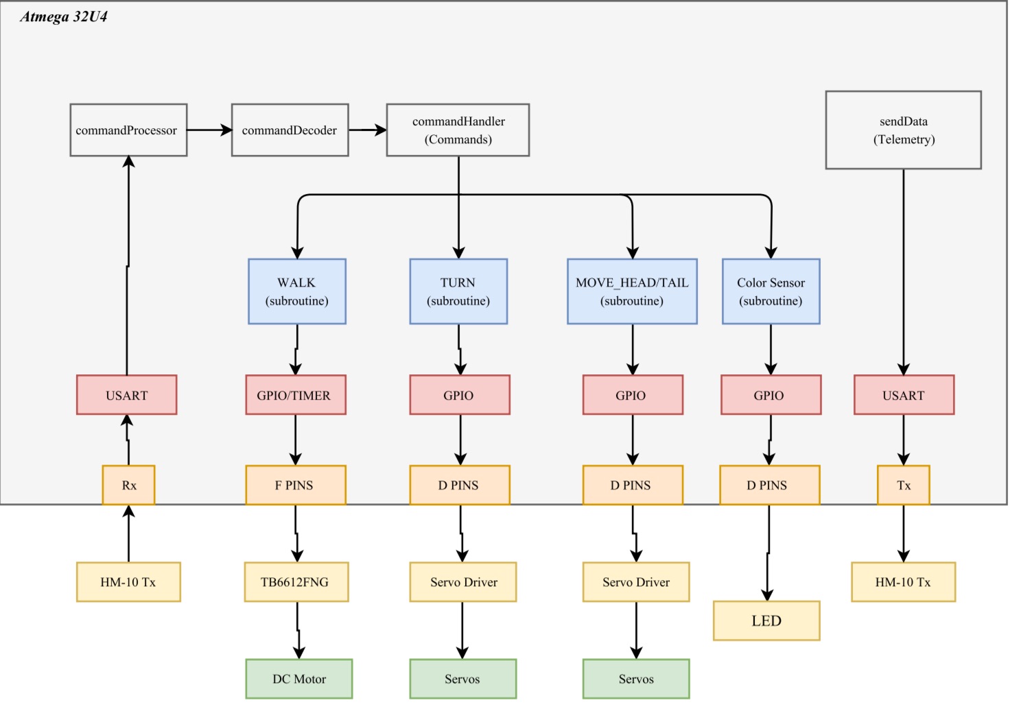
The Velociraptor software contains four different subroutines. Three subroutines control the robots movements and one controls the color sensor and LED. The software begins by first decoding incoming data packets, then each subroutine is called based on the decoded command in the commandHandler. Also please note that the subroutine for the Head/Tail movement was removed in the final design since we decided to use it for cosmetic purposes instead.
There were a series of steps that had to be run through in order to choose the different types of parts for our robot. In the link below, we have a slide-set detailing the different parts that we used for our robot.
The firmware design for the robot can be found in the following link below.
Included is a blog post that goes through the stages which our schematic, PCB, and construction went through during our project design.
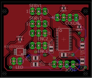
Finalized PCB Layout Design
Below is a series of blog posts which takes you through the hardware design and assembly process that our manufacturing engineer went through as she continuously developed new designs and models through the engineering iterative design process.
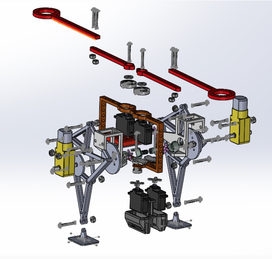
Exploded View of Velociraptor
Our verification & Validation test plan can be referred to in the link below. The other link includes the verification matrix detailing which requirements we were able to meet throughout the engineering design process.
Verification & Validation Test Plan
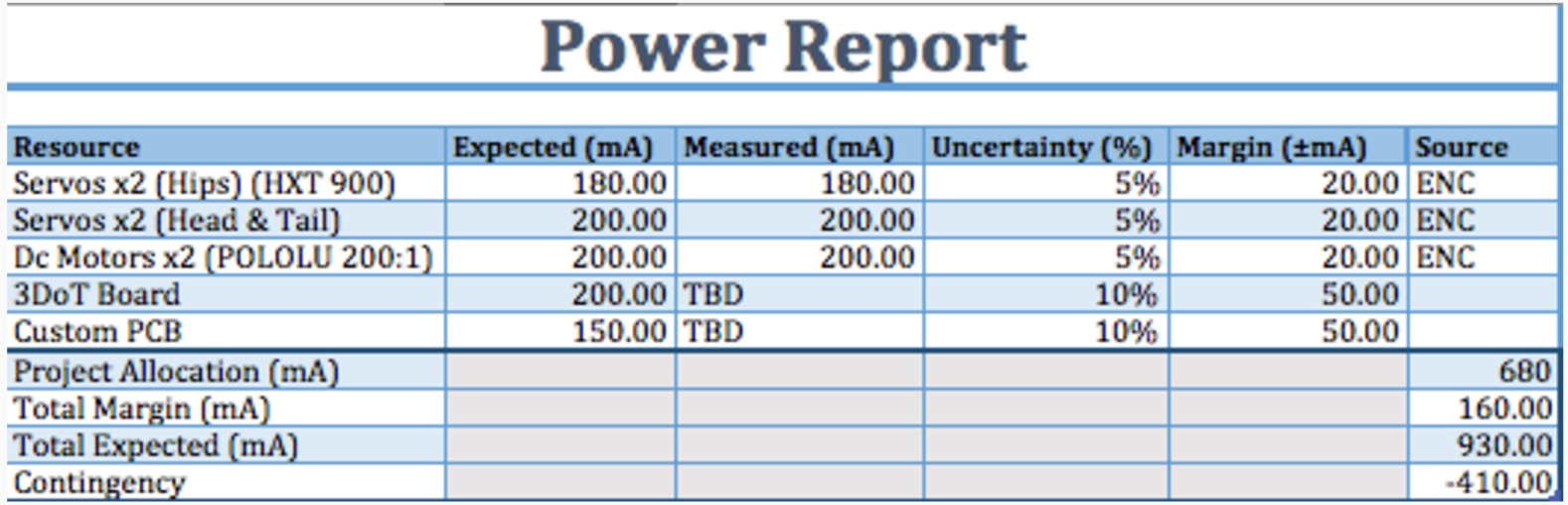
The Power Report shows that the Velociraptor team is at ~930mA and the Project Allocation is at 680mA. In this case we had a negative contingency which meant that we were allocating too much power to our original design. Later on, we ended up taking away some of the components such as DC motors and Servos which dropped our contingency for a positive note.
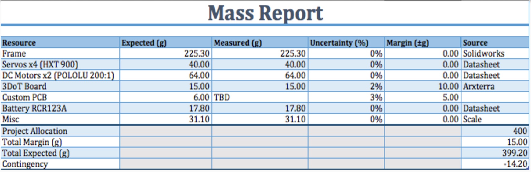
The Mass Report is based upon the torque needed to drive the robot, which is ~400g. The robot weighed 889g which was because we ended up decided to make the robot a lot larger in size than that of the original anticipated design.

Looking at the cost report above, we can see that we went well over our budget. We had an allocated budget of $200 originally and spent a total of $361.25 in the end. For future suggestions, it is better to do research on getting parts from personal vendors rather than distributors (i.e. McMaster Carr) in order to get parts for a cheaper price.
Much of the top level schedule had remained the same mostly throughout the duration of the project. This was mainly because most of the time we could not really push back important deadlines for the top level at all. As for the system level, this one tended to be very dynamic throughout the duration of the project since there was consistent design changes throughout the semester which continuously pushed tasks back.

The project overall started off very steady getting things done on time in the beginning since they were mostly top level tasks. Although as we started to dive into the system level tasks, we started to delve off-track which was tied to a lot of the iterative design changes we were making. In the end, we were not able to finish 100% of the tasks which we hope to which was caused to consistent errors and mistakes such as accidental drops or parts being burnt out from time to time. Expecting the unexpected and being prepared is suggested for future purposes because anything that can go wrong, will go wrong sometimes.
Below are a few suggestions for some of the things our group encountered as we went through the engineering design process for this project:
Last but not least, please do ask Professor Hill for help since he did come up with idea at the end of our project which we should have came to him for in the first place. Using your resources and communicating across all management levels is extremely important.