Pick and Place – 12 Servo Mount & Tape Feeder System
By: Tyler Jones (Manufacturing) and Belinda Vivas (Project Manager)
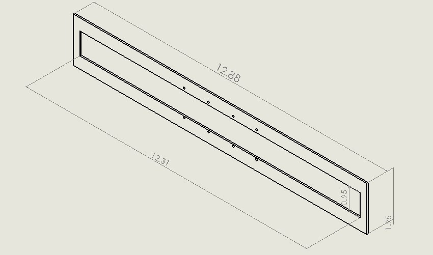
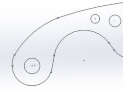
Figure 1
In order for the pick and place machine to be able to complete one board, it must be able to pick and place many different devices for a whole board. It must be able to pick and place capacitors, and resistors of varying sizes 0402, 0603, and larger. For the purpose of the 3DoT board the components must be 0603 sized. The parts are dispensed either using the mounted reels, or the individual manually feed part tape. In order for the tape to advance the parts into the reel feeder system uses servos to run and pull the plastic cover from the SMT part tape.
Directions on how to correctly set up the tape is contained in the instruction manual. The 12 servos are mounted on an equally spaced servo mount shown in Figure 1. Additionally two sides must be created to create a “U” shaped servo mount. Shown below are the aluminium side pieces in Figure 2.
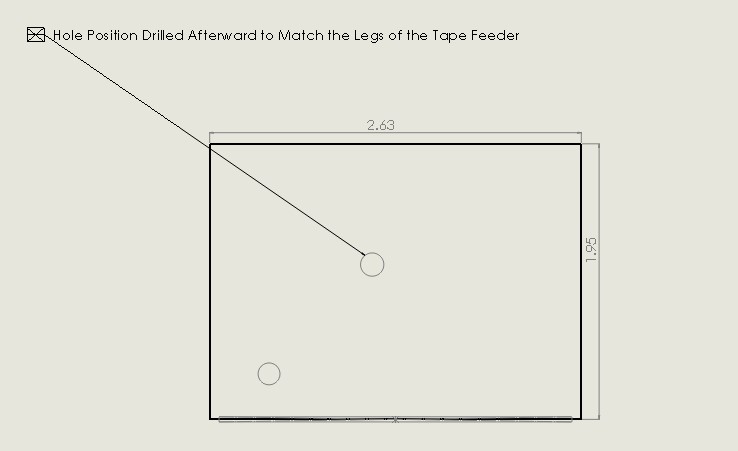
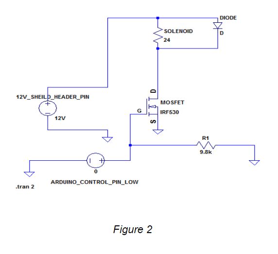
Figure 2
Regardless of whether the user chooses to use the reels or the individual manually cut strips, the servos must advance the tape and be able to not only collect the protective outer tape film that encloses the parts, but also move the second part into the same position as the first part was in, after the first part has been placed.
Fabrication of the servo mount must incorporate 12 or more servos to be mounted on to a platform above the surface so that they can be programmed and calibrated to turn a certain distance that is calculated to move the second part forward to the same position. The servos are equally spaced in 1 inch intervals. It is important that the servos are positioned at the same distance from the base of the feeder trays. This is to ensure that the individual calibration of each servo is relatively in the same range of motion for turning, and that the force of tension on the tape is relatively similar. This can be seen in Figure 3 below.
Figure 3
The entire platform must be mounted on to two legs that support the servo platform. This is shown in Figure 4.
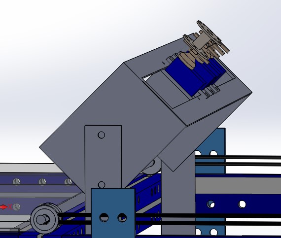
Figure 4
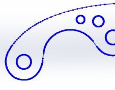
The servo platform and two sides had to be cut from 6061 0.125 inch aluminium. The aluminium was donated by the SAE. The aluminium was cut using a programmable plasma cutter. The plasma cutter utilizes a DXF file in order to create cutting lines. The part was created in SOLIDWORKS. The part was then converted to a DXF file in SOLIDWORKS. These are shown in Figure 5 and Figure 6 below.
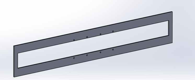
Figure 5
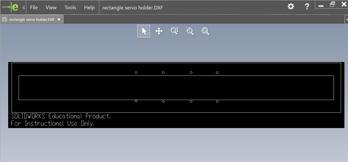
Figure 6
The servo mount was drilled in twenty four locations with a drill bit that can accept M3 sized bolts. The servo mount was then assembled using very small M3 sized bolts. The bolts. were fitted with M3 sized nuts, and washers. The servo platform was welded to the two sides using a TIG welder system in order to join aluminium. The welding is shown below in Figure 7 and Figure 8.
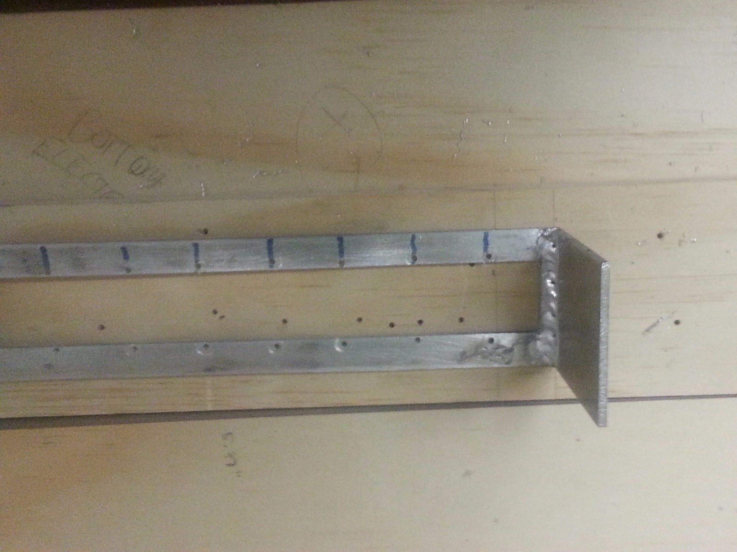
Figure 7
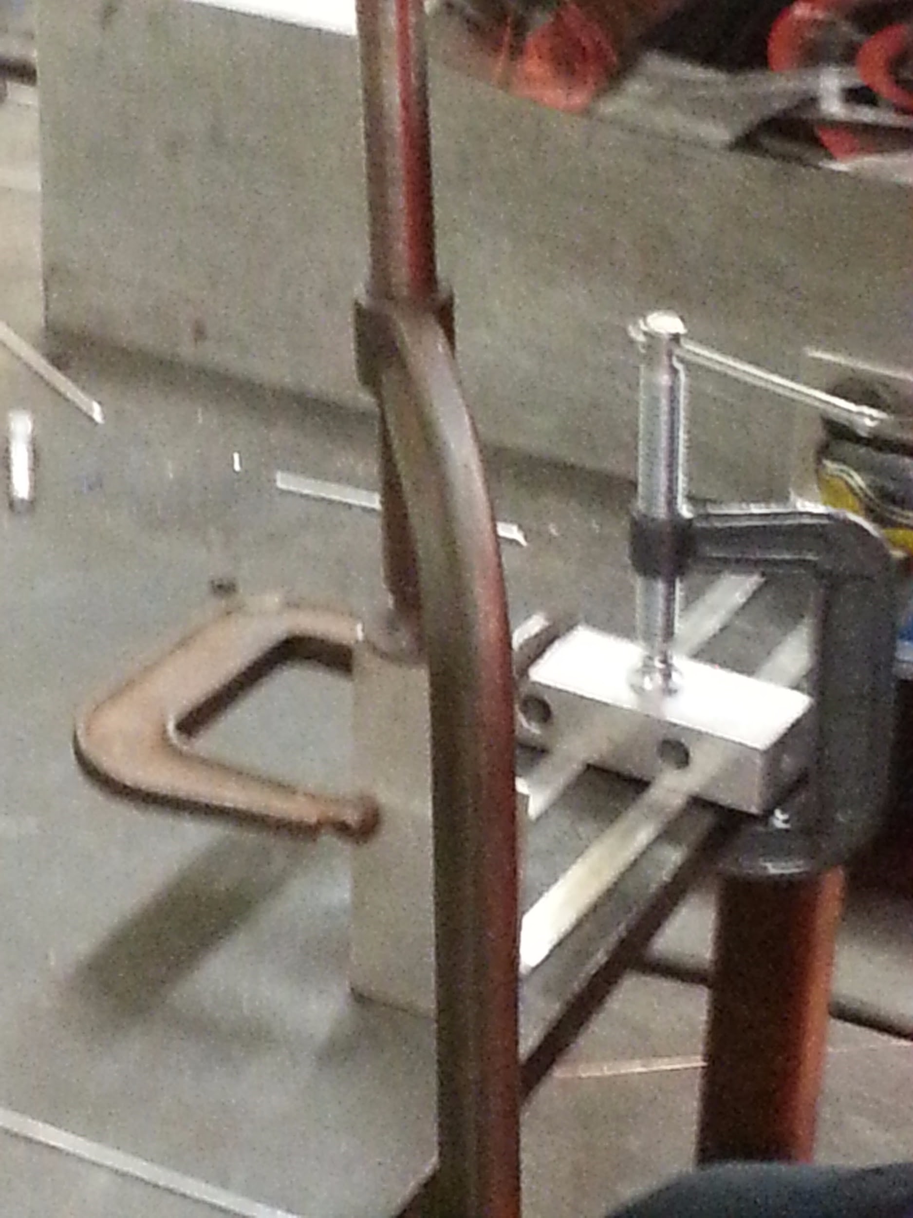
Figure 8
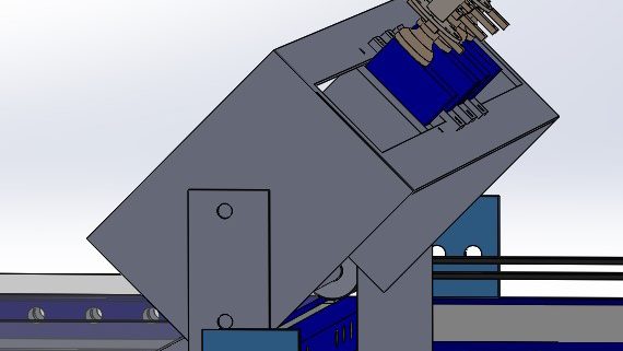
After the full assembly has been welded together, and the holes were drilled, now the servo holder can be mounted. It is important to bolt the entire platform tightly to the legs which are bolted to the tape feeder platforms. The servo platform must be placed on the legs at a 45 degree angle. This helps to create a optimal pulling force of the outer tape. The completed servo mount is shown in Figure 9 and Figure 10. The servo motors come with circular discs that attach to the shafts of the motors. Some gorilla epoxy was applied to standard sewing spools shown in Figure 9. The spools are then fitted onto the servos and can now function as a tape cover collector, and as a way to force the tape onto the aluminium table. Information and instructions on how to force the tape onto the table is contained in the instruction manual, as well as the Feeder Tray post.
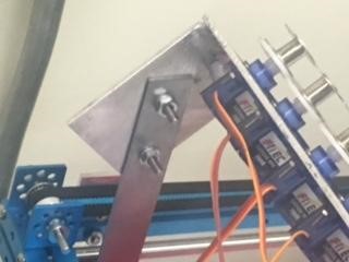
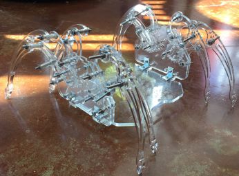
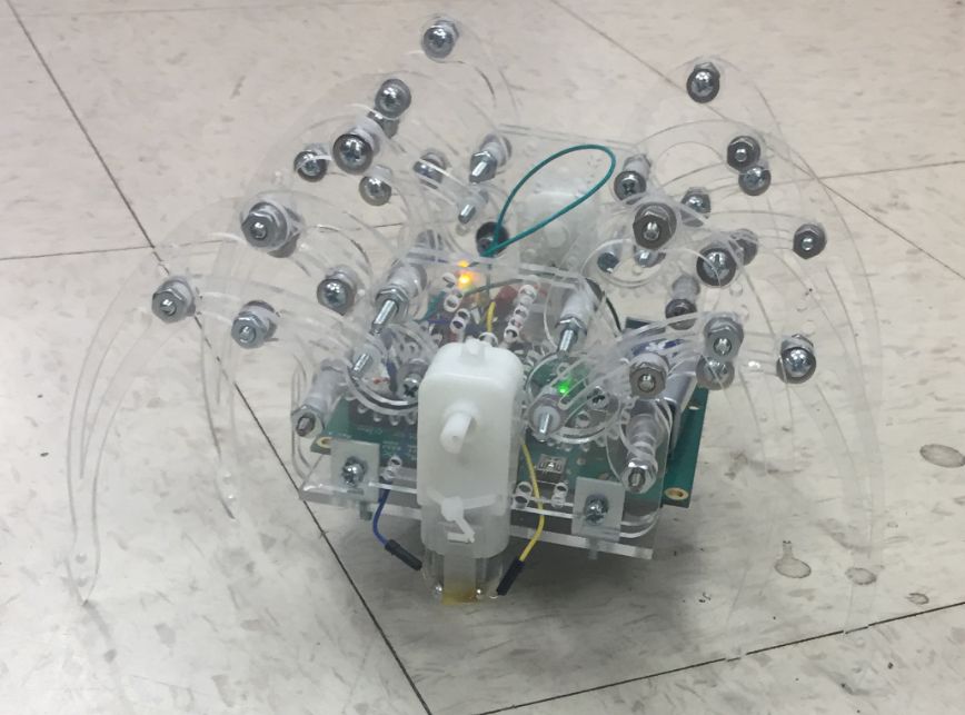
Figure 9
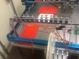
Figure 10