Spring 2017 – Spiderbot – Torque Test
Torque Testing
By: Shaun Pasoz
Electronics & Control Engineer
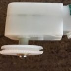
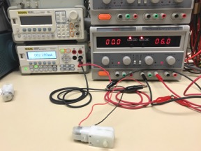
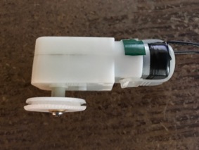
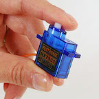
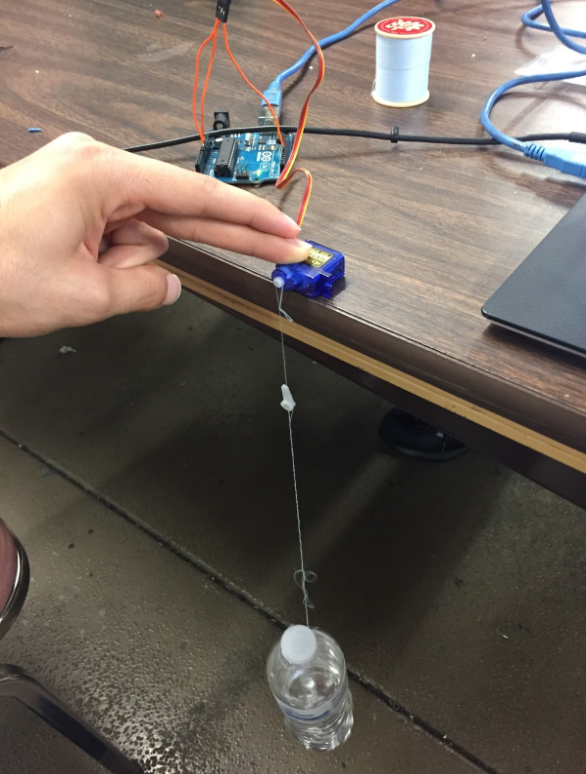
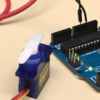
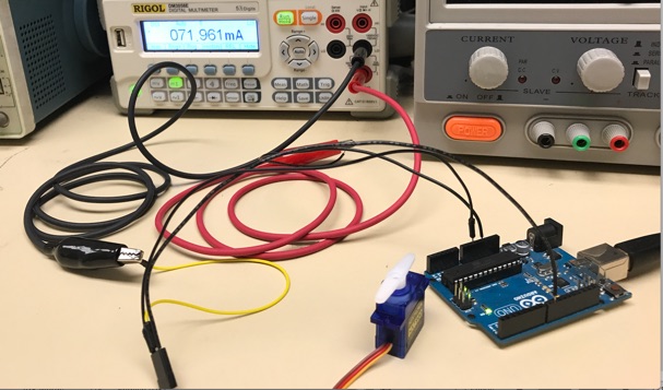
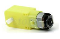
Torque testing allows the designer to see if a desired motor can output enough force to physically move a robot. To perform the test, a rig was designed in which the motor was clamped down with a fixed radius on the output shaft. Varying weights were then hung from the fixture using a very thin fishing line. This setup allowed for the force pulling the weight down from gravity to always be tangential to the fixed radius, allowing for simpler calculations of torque using the following formula:
τ=rFsin(θ)
The variables used to find torque are:
- F = Magnitude of the force applied to the lever arm
- r = Radius from axis to the point of applied force
- θ = angle between r and F
Since the designed rig allows the force to always be tangential to the radius, the equation is simplified to τ=rF. To control the amount of force on the radius, the weights are used to continually increase the force. Therefore, the final equation for calculating the torque is:
τ=r*mg
The following tables show the data measured during the torque testing:
| Motor: | Sparkfun MicroGear Motor @5V | ||
| Mass (g) | Current Draw (mA) | Radius of Fixture (mm) | Torque (Oz-In) |
| 0 | 32.7 | 1.50 | 0 |
| 250 | 38.5 | 1.50 | 0.520 |
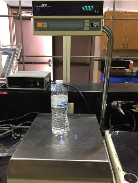
| 300 | 40.8 | 1.50 | 0.625 |
| 500 | 44.5 | 1.50 | 1.04 |
| 700 | 48.6 | 1.50 | 1.46 |
| 1000 | 55.1 | 1.50 | 2.08 |
Table 1: Sparkfun Torque Testing Data
| Motor: | Pololu MicroGear Motor @3.3V | ||
| Mass (g) | Current Draw (mA) | Radius of Fixture (mm) | Torque (Oz-In) |
| 0 | 40.1 | 1.50 | 0 |
| 500 | 114.8 | 1.50 | 1.04 |
| 700 | 128.5 | 1.50 | 1.46 |
| 900 | 141 | 1.50 | 1.87 |
Table 2: Pololu Torque Testing Data
Figure 2: Torque vs Mass Graph
Since both the radius, and the angle between the force applied and radius, the relationship between torque and mass is going to be the same for both motors. Where they begin to differ is when the other parameters of the motor are observed. For example, the current draw of the Pololu motor was over double with a 700 gram load on it. This is because the motor has been chosen to run at 3.3V instead of 5V to accommodate the customer’s needs.
The SpiderBot’s expected mass is 700g. The required torque to move 700g was calculated to be 1.46 ounce-inch. Both motors have a stall torque well above that, and therefore should be able to safely move the SpiderBot.
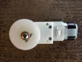
With the expected load, the Pololu motor RPM was calculated at 44 RPM. This was found by putting a piece of tape on the radius and counting the revolutions for 30 seconds three times and taking the average. Repeating the process for the Sparkfun motor; it’s RPM was calculated as 33.3 RPM. Some possible deviations may occur as possible sources of error include: neglecting the weight of the weight of the fishing line that pulled the weights, and not including the various friction points in the calculations. Overall, the motors should be able to move SpiderBot without damaging the 3DoT or our PCB.