Preliminary Design Document includes everything from the Project Objectives and Mission Profile to the Design and Unique Tasks Descriptions of the Project
Velociraptor Team:
Jesus Enriquez (Project Manager)
Oscar Ramirez (Mission, Systems, & Test)
Mohammar Mairena (Electronics & Control)
Andrea Lamore (Manufacturing)
Table of Contents
By Jesus Enriquez (Project Manager)
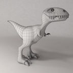
The Velociraptor Biped, inspired by that of the Titrus-III model developed by the Tokyo Institute of Technology, is to meet customer expectation through demonstration in a negotiated battle defined between the customer and the Robot Company project teams. While carrying out the mission, the Velociraptor will be operated through video support from a remote location using an assigned support vehicle from The Robot Company. The Velociraptor will be further controlled by a designated user through the Arxterra mobile application.
References:
EE 400D S’17 Project Objectives and Mission Profiles
By Jesus Enriquez (Project Manager)
References:
Fall 2016 Velociraptor (Th): Preliminary Design Document
Spring 2016 Velociraptor: Preliminary Design Document
By Oscar Ramirez (MST)
By Mohammar Mairena (E&C)
By Andrea Lamore (Manufacturing)
References:
https://www.arxterra.com/fall-2016-velociraptor-preliminary-design-documentation/ https://www.arxterra.com/3dot
https://www.arxterra.com/fall-2016-velociraptor-th-preliminary-design document/#Electronics_Subsystem_Requirements
By Jesus Enriquez (Project Manager)
After researching through the different designs of the previous generations of Velociraptor Biped Robots, it was noted that the certain types of leg mechanisms such as the Theo Jansen linkage was not appropriate to get the Robot to walk in a dynamic fashion but rather a static motion since it can only move forward and backwards rotating along a single axis. This limits the robot in terms of flexibility to move and turn in a dynamic fashion. Considering the mission of this robot per the customer’s request, it is essential that the robot have flexibility in its ability to move and turn under certain conditions. Using the creative process, our group was able to generate a few solutions.
By Oscar Ramirez (MST)
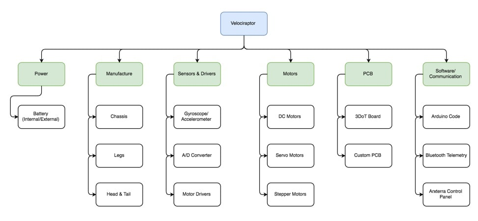
Power
The Velociraptor Biped will be powered by a portable power source that while not taking away any functionality or balance to the Biped must also be able to power the robot.
Body
The frame of the robot must have a strong material considering it will have a higher center mass when walking dynamically. The frame will consist of the head, tail, legs, and chassis. Aluminum will be ideal for this since it is not only a strong but lightweight material. Aside from the physical advantages to using aluminum the cost will also benefit the design since aluminum is going for about $30 per 4 square feet at 1.6mm thickness. This translates to a little more than one and a half kilograms of aluminum but not all of the 4 square feet sheet will be used and the frame of the robot will likely be the bulk of the mass.
Sensors and Drivers
An accelerometer will be used to help while walking to track motion and ensure that the system is not off balance. An analog to digital converter will also be used with the DC motors to track the position of the motors rotation and translate it into digital data that will be read into our microcontroller. Drivers will also be used for the DC motors since the microcontroller cannot directly control the speed of the motors.
Motors
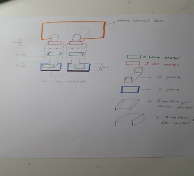
As required by the customer, DC motor will be incorporated into our design. There will be two total DC motors that will provide motion to our Velociraptors legs and carry the majority of this load. Servo motors were used in the past but DC motors are better suited for the task since the can handle more torque. Servo motors will still be used in our design but they will be restricted to controlling the head and tail to move in sync with the center mass of the robot. Stepper motors will also be used to help provide more stability and needed torque for the legs.
PCB
There will be two PCB boards incorporated in our design. One of them will be our 3DoT board that will contain our microcontroller and control the servo motors and the other will be the main PCB board that will have all other sensors, communications systems, and drivers.
Software and Communication
The Velociraptors software will be based in C++ and written in an Arduino sketch. This sketch will control all motor functions and communicate to the Bluetooth module. The Bluetooth module will then sync with the users Android or iOS device and be controlled via the Arxterra control panel application. This application will have a GUI that will let the user perform any function of the robot such as walking, turning, and use of the on board secret weapon.
References:
http://arxterra.com/fall-2016-velociraptor-preliminary-design-documentation/
https://www.metalsdepot.com/products/alum2.phtml?page=sheet
https://www.arduino.cc/
https://www.arduino.cc/en/Main/ArduinoMotorShieldR3
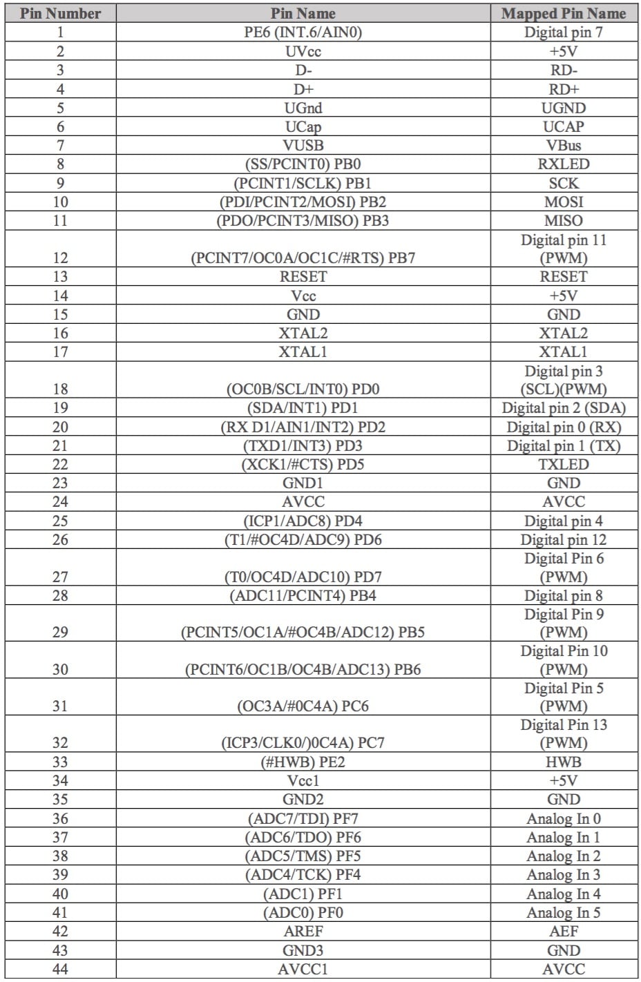
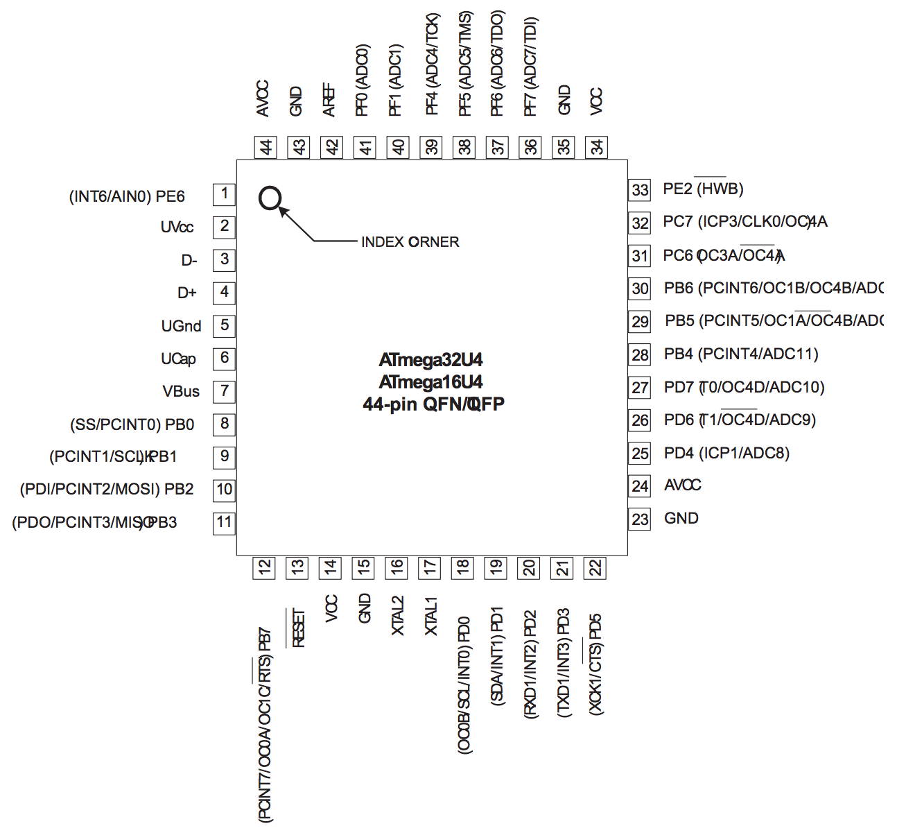
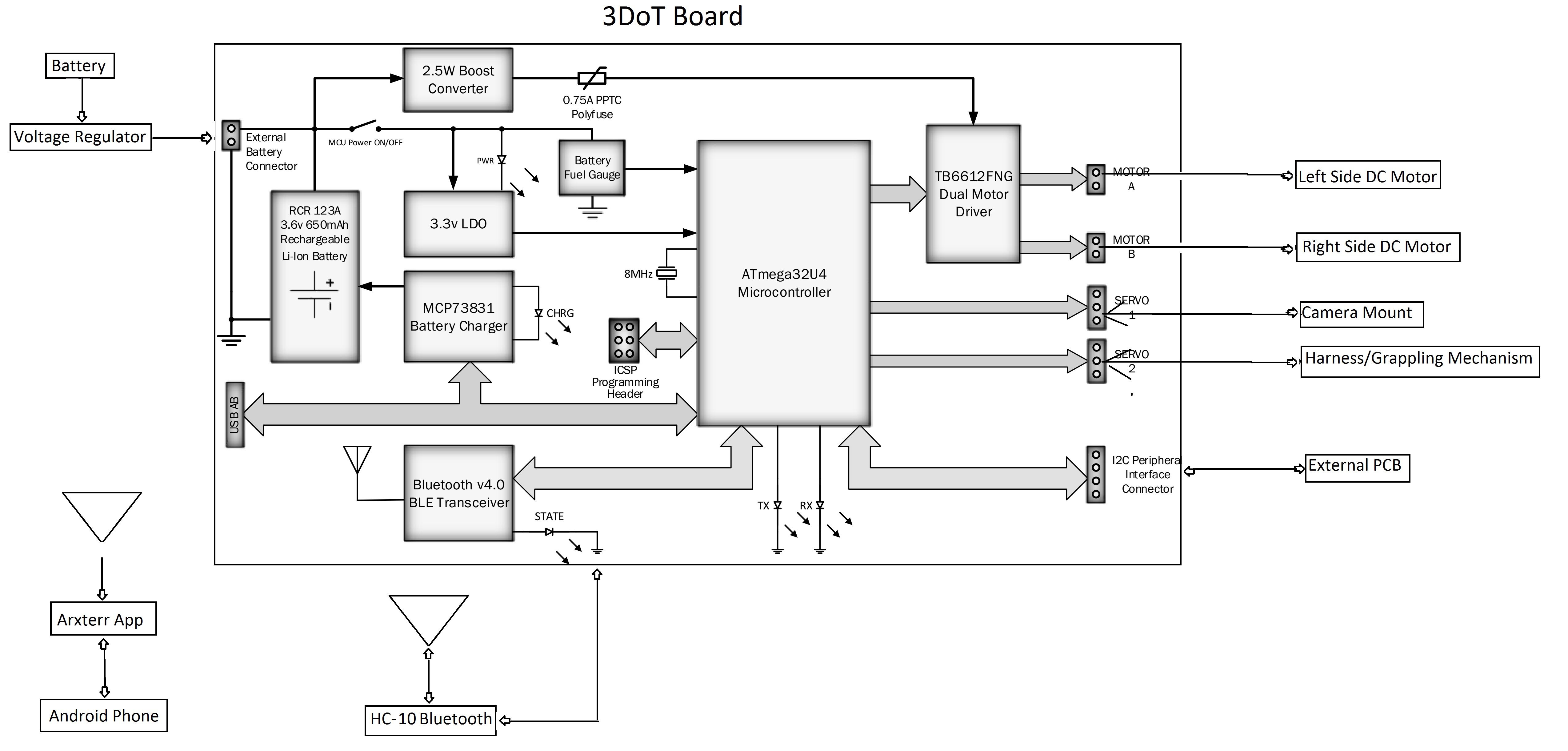
By Mohammar Mairena (Electronics & Control)

Shown above is the block diagram for the electronic design. Within the 3DoT board is the I2C interface that allows the user to add multiple devices using the SDA and SCL pins (data and clock, respectively). The block diagram highlights the importance of the micro-controller as the root of each and every device as well as the significance of the micro-controller in terms of communicating with certain devices.
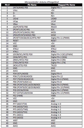
By Jesus Enriquez (Project Manager)
Reference:
https://www.arduino.cc/en/Hacking/PinMapping32u4
By Andrea Lamore (Manufacturing)
The velociraptor design be broken down in the following: The legs, feet, and the head-tail.
The entire design is going to be top-heavy and tall. Making the device top heavy will allow for good traction to floor and a small moment of inertia at the body so the top (the body) is more stable than the legs. The tall height in the legs makes it so there is a longer radius between the body and the feet, this also increases the moment of inertia at the body. A longer radius will give the robot more time to catch itself.

Leg Structure
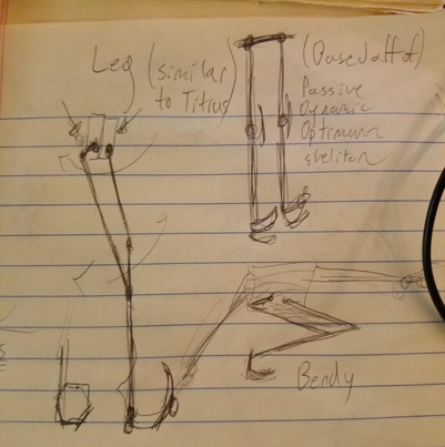
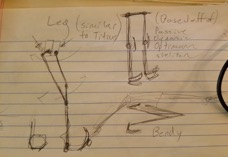
The leg’s structure is going resemble that of a robot’s that is able to complete a passive dynamic walk. Without a mechanical control for preventing “bounce back” in the knee (referring to the knee bouncing back to bent after straightening), the leg design will not be able to complete a passive dynamic walk. Instead of a mechanical mechanism to prevent bounce back, there will be two motors used to control each leg – like the Titrus III design. One motor is responsible for the knee motion and the other for the swing of the hip. Using a combination of the successful passive walking robot and the Titrus III model, we will be able to create a leg that has the physical structure required for both passive and dynamic walking.
Static Walk
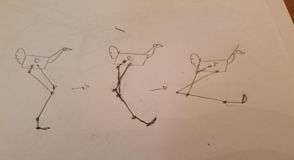
For the static walk the legs will be crouched by bending the knee and rotating the hip. This crouch will lower the center of mass and make the robot’s stance more stable. In the crouched position, the robot will utilize its head and tail to shift the center of mass from side to side depending on the foot that is stepping. In the crouched position the knees will move forward and the robots center of mass will be shifted, the upward motion of the head will be used to compensate for that forward motion. The tail will be capable of being used as a third leg so that the robot may utilize a very stable tripod stance.
Turning
Turning will be controlled by motor as the hips. The motors responsible for turning will be placed here in order to keep the top heavy and reduce bulk in the legs so that the legs may accelerate as fast as possible and thus catch the robot as it falls on each step faster. The hips, if viewed from the top will angle the leg away or towards being in parallel with the other leg.
Feet
The feet will be statically joined at the ankle in order to reduce the amount of motors needed. If the legs need not enter the crouching position then the static flat foot with the heal attached to the ankle would suffice, however, since the robot will be crouching, the foot will need to roll over onto a different plane in order to keep the robot stable. To solve the problem, the robot will be able to bend its leg backwards (in the opposite direction of the dynamic walk bend) and roll over onto the ankle plane which will be at a slightly different angle from the rest of the lower leg.
Head/Tail
The head and the tail will move up & down and side to side. This mechanism will be that of the Titrus III robot, which used a “horse reign” schematic to control the head and tail. This “horse reign” method is similar to the reign of a horse in that two motors control the head/tail to move wither side to side or up and down. When one of the motor is rotated the head will turn either away or toward the motor in motion by moving left to right. If both motors are rotated in the same direction the head/tail will either lift or fall to the ground.

References:
https://www.youtube.com/watch?v=rhu2xNIpgDE&list=LLNnlTvhtytEM7T9W2Ou5IGA&index=27
https://www.youtube.com/watch?v=GxVv4WNlXMA&index=29&list=LLNnlTvhtytEM7T9W2Ou5IGA
By Mohammar Mairena (E&C)
The battery used to power the Velociraptor must take into account a few things such as: current capacity and mass of the battery with relation to the robot’s total weight. In order to choose the right battery in accordance to its specifications, tests must be run. The Servo motor will be under different load conditions and we will record measurements for current drawn in each unique load condition. Additionally, the operating voltage for DC and Servo motors will be 5V.
Velociraptor Electronics & Control Tasks
Belinda Vivas (Project Manager)
Amber Scardina (Mission, Systems, and Test)
Kevin Ruelas (Electronics and Control)
Tyler Jones (Manufacturing)
Chastin Realubit (Manufacturing)
Table of Contents
By: Belinda Vivas (Project Manager)
The second generation of the Pick and Place will create a 3-Dot 454 PC Board. It will ensure precision through the addition of a camera system, addition of a variety of components, design upgrade, and a user friendly mechanism. A CSV file will be created for this generation, to implement a better interface between the user and the machine. A manual will be provided for this generation, as well as for the Madell Pick and Place for which extensive research is being done to implement the design of the camera (edge detection) system and software interface. A more detailed list of the customer’s needs can be found on the link provided.
http://web.csulb.edu/~hill/ee400d/S’17%20Project%20Objectives%20and%20Mission%20Profile.pdf
By: Belinda Vivas (Project Manager)
Level 2 System Requirements of Pick and Place (1st Generation) Analysis
By Amber Scardina (Mission, Systems, & Test)
Listed above are the Level 2 Requirements for the first generation pick and place. The Level 2 Requirements for the first generation demonstrates the functionality of the current pick and place machine. After analyzing these requirements, the following updates need to be made:
Given the updates listed above, the other level 2 requirements from the pick and place first generation should still hold true for the second generation, exhibiting the same functionality. After trade-off are conducted, more updates and level 2 requirements for the software and manufacturing subsystems may be required in order to successfully verify and validate the level 1 requirements. Additional Level 2 Requirements will be included in the second generation to make the pick and place user-friendly. In the next section below, the level 2 requirements for the pick and place second generation is listed.
Source Material:
Level 2 Subsystems Requirements of Pick and Place (1st Generation) Analysis
By Amber Scardina (Mission, Systems, & Test)
The level 2 subsystems requirements for the pick and place 1st generation can be found in the following link:
https://www.arxterra.com/spring-2016-smd-pick-and-place-machine-preliminary-design-document/
The subsystem requirements should still hold true for the second generation. The system should contain the original manufactured parts (except the reel mechanism), with the addition of new parts to verify and validate the level 2 system and level 1 program/project requirements. The level 2 subsystem requirements helped describe the functionality of the system that will be incorporated into training materials for the second generation.
Level 2 System/Subsystem Requirements of Pick and Place (2nd Generation)
By Amber Scardina (Mission, Systems, & Test)
1. The pick and place shall have an attached compartment to hold accessories for the pick and place. Accessories for the pick and place may include: pump, paste, components, etc.
a. The dimensions of the pick and place and the attached compartment shall meet the EE 400D cabinet specifications.
b. The attached compartment shall not interfere with the functionality of the pick and place machine.
2. The pick and place shall meet the EE 400D cabinet specifications for storage purposes.
a. The legs of the pick and place should be raised to meet of the specifications of the attached compartment.
b. The Z/A axis should not be removed from the pick and place in order to be stored in the cabinet.
3. The pick and place shall incorporate a camera.
a. The camera of the pick and place shall be used to incorporate edge detection technology.
4. The pick and place shall have resources to aid the user of the pick and place in set-up and configuration of the pick and place.
a. The resources for the pick and place shall include a video tutorial on how to handle (set-up) and configure the machine.
b. The resources for the pick and place machine shall include a written manual to assist the user in set-up and configuration.
c. The pick and place shall include sample (test) files for the user to practice with the machine.
d. The resources for the pick and place shall include a section for troubleshooting the machine.
5. The pick and place shall have a case to protect the pick and place from its surroundings.
a. The case shall enclose the machine to meet the EE400D cabinet specifications.
6. The pick and place shall produce a 3Dot board in a specified time. This specified time is currently set for one hour, although after trade-off studies are conducted this time may change.
a. The pick and place shall be faster than human production time. Human production time for a 3Dot board is currently established as four hours.
7. The user of the pick and place shall be able to set-up and configure the machine in a specified time. This specified time is currently set for two hours, although after trade-off studies are conducted this time may change.
Source Material:
1. https://www.arxterra.com/spring-2016-smd-pick-and-place-machine-preliminary-design-document/
2. http://web.csulb.edu/~hill/ee400d/Lectures/Week%2004%20Modeling/b_L2%20Requirements.pdf
By: Belinda Vivas
A creative exercise was executed by the members of the team to begin the process of brainstorming ideas to incorporate new innovative design ideas for the Second Generation of the Pick and Place. Focusing mainly on the problem of mounting the electronic components into the PC Board without them moving out of place. Also, how to implement a better overall design for a more user friendly generation.
https://drive.google.com/open?id=0B9iWYCBTJWEERHB6Y1BHX2owdFU
By Amber Scardina (Mission, Systems, & Test) and Belinda Vivas (Project Manager)

The Product Breakdown Structure (PBS) demonstrates the updated system and subsystems for the Pick and Place 2nd generation. The updates for the pick and place can be classified in three categories: Customer Interface, Software, and Manufacturing. These categories are described by the Level 1 Program/Project Requirements. The customer shall interface easily with the pick and place machine by giving the customer numerous resources for set-up and configuration. The software will be updated to accommodate customer interfacing, in addition to new edge detection software that will be written for the camera. A possible LCD may be incorporated to display the current electrical components that need to be loaded or placed. The pick and place will also undergo several manufacturing updates. The manufacturing updates on the pick and place includes a nozzle redesign to accommodate a camera to implement the edge detection software. The pick and place machine will also add more feeders and component trays to accommodate a 3Dot board with different type of components as well as an underneath compartment to store accessories for the machine. Accessories for the machine include: pump, paste, stencil, power cords, and electrical components. Other manufacturing additions include updating the specifications of the pick and place machine to accommodate the EE400D closet. After trade-off studies are conducted, the technical requirements for the pick and place 2nd generation will be more clea defined.
Source Material:
1. https://www.arxterra.com/spring-2016-smd-pick-and-place-machine-preliminary-design-document/
By Kevin Ruelas (Electronics and Control Engineer)
A Cameras should be installed on the machine to incorporate edge detection software. Edge detection will function when the component is picked up and measured and placed onto the board. More research will need to conducted in order to develop the edge detection software.
Another design option: An additional camera can be used to detect whether a component is present on the tray or not and display an “error” message if the tray is empty. Cameras should be chosen so that it is able to capture a high resolution image of the smallest component the machine can pick up. (0402 size). They may also require flash LEDs in order to achieve a bright and crisp image.
A small screen should be installed and display the current component being picked up and placed onto the board. This display should also display the current status of the machine. Depending on its current operation, a user input pad will be considered. User should be able to input component coordinates and name and press a “Place” button to place the part. Size of the display and place of installation is still pending. Software for the LCD display will need to be developed.
The wiring for the pick and place should remain unchanged from the first generation.
A kill switch should be implemented to isolate the machine from power in case of emergency or for maintenance. Software for the kill switch will need to be developed.
By Amber Scardina (Mission, System, & Test) and Belinda Vivas (Project Manager)

The system block diagram above describes the how information is sent in the pick and place system. The information is sent from the user using EagleCad, converted into Gcode, then sent to the microprocessor (Arduino Uno). From the Arduino Uno, the data is sent to a Me Orion board to control the motors for each axis. With the addition of a camera and edge detection technology, the system will allow for calibration of coordinates if necessary. Once the nozzle is confirmed to be at the correct coordinates, the data is sent to
By Amber Scardina (Mission, System, & Test) and Belinda Vivas (Project Manager)

The diagram shown above describes how the user will interface with the pick and place. Note: this method has remained unchanged from the first generation.
The link below shows the pin mapping of the Arduino Uno, which will be the same implementation for the second generation of the Pick and Place:
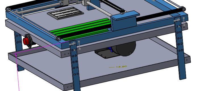
By Tyler Jones – Manufacturing
The basic overview of the current design for the pick and place is fully functional and can place 0402 components, as well as larger size components such as integrated circuits and 0603 sized components. The pick and place machine operates on a belt system in the X and Y axes. The Z axis contains the nozzle which can be lower and lifted using a linear actuator. The machine is controlled from an Arduino Uno microcontroller and Me Orion shield. Currently the software is being retested and calibrated for use.
The second generation requirements for the pick and place however will impact the current design. The second generation mechanical design will need to fulfill a size requirement of being able to fit in storage cabinets. Also a much more user friendly design must be incorporated so that the average user can easily manufacture boards without advanced technical knowledge. This will call for a smaller, more compact machine, and must be able to maintain the current precision and accuracy of the first generation. The Z- axis must be able to turn on a geared platform 90 degrees for setup and take down this eliminates the height problem.
The requirements also specify a speedy setup process so that boards may be manufactured quickly. This will call for an all in one style machine without any lose parts. Also the current design implements an automated reel feeder system. This will have to be re -designed however because the second generation will be designed to populate a 3DoT board, using a variety of more components. This renders the reel feeders to be useless because they can only provide thousands of only six types of parts. Additionally the current IC tray must be re-designed because it should also offer a more versatile range of ICs to be used.
In order to fulfill user friendly requirements the pick and place should incorporate a small emergency stop button on the side this will shut off the power to the machine if there are any errors or malfunctions being used. Each of these design elements; the new feeder system, the new sizing, new Z axis that can rotate, and the push button will be discussed further on in this article.

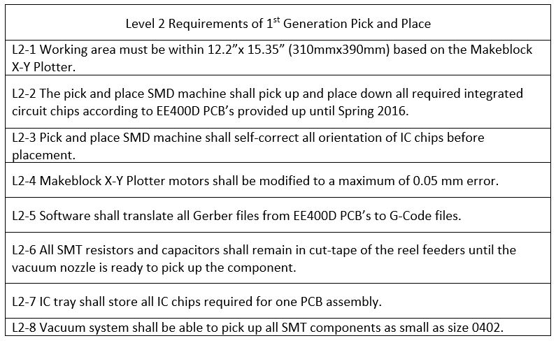
The feeder trays can be made so that the grooves fit a universal tape reel size. This will allow multiple types of tape sizes to be fit into the grooves.
The trays can be 3D printed using ABS plastic and color coded according to part sizes.
Multiple trays can populate the table so that all parts can be utilized by the machine.
The groove size for the tape reels to fit snugly without stalling the tape is 0.317 inches.
The length of the groove should be enough so that at least 30 of each part can fit. This will safely cover the maximum number 3DoT board’s parts that are identical for each individual board design.
A tape peeling and reel feeding mechanism may have to be employed after exploring the software capabilities.
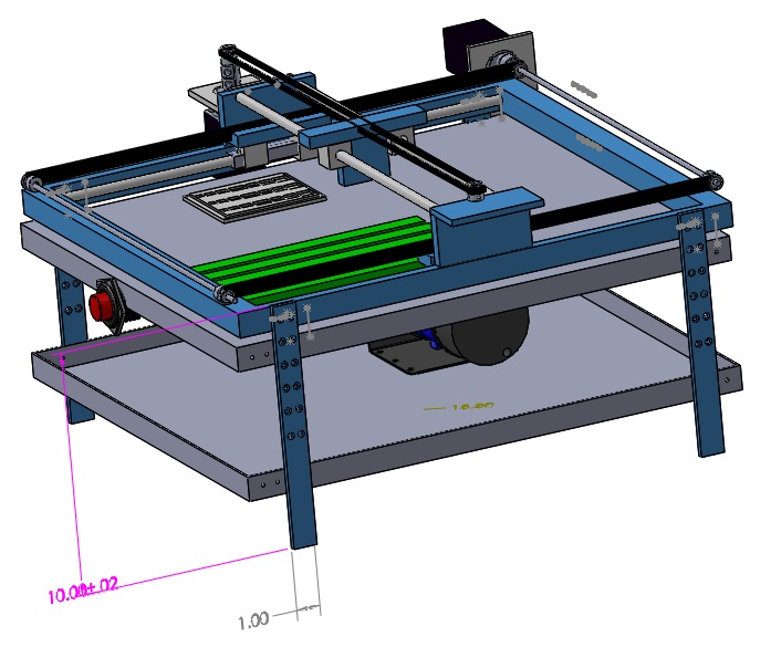
The 2nd Generation Pick and Place must be made smaller. This is so that the machine can be easily transported, and setup for ease of use. The image above represents a solid works draft of the machine. The legs can be lengthened by 4 inches providing a space below the pick and place so that the pump can be mounted.
This also makes it so that the pick and place can be stored in a cabinet in the upright position. It provides a convenient area to have the used part tape land, as well as an area for putting the spare components or component strips. The under tray can be made from aluminum or sheet metal so that the pick and place is still lightweight.
Getting rid of the reel feeder system provides more stability, because there is no longer an aluminum feeder and large reel hanging from the side of the machine. This also cuts down on height and width, as well as weight.
The absence of a reel feeder also creates more surface area to populate the picking surface with more IC trays and cameras.
The diagram above shows how the Z – Axis can be rotated by 90 degrees from vertical to horizontal.
Using a rack and pinion the whole Z – axis can be rotated and locked into position. This allows for more height clearance and ease of use. The Z axis stands 7.5 inches above the XY Axis. Allowing the Axis to be locked in 90 degrees from the Z axis eliminates all but about 1 inch to stand above the Axis. This creates enough room to store in a cabinet.
It is essential that the locking mechanism be very tight in order to prevent misalignment. It is also essential for the mechanism to be simplistic and small itself.
![]()
![]()
![]()
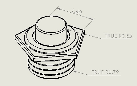

The schematic above shows the sizing and dimensions for the emergency push button. This will be implemented as a way to stop the machine from processing any further components. The position of the button needs to be within reach of the operator, and on the same axis as where the parts are placed into the grooves.
Depending on the software development the emergency button may be implemented in power circuit as an override switch.
By Amber Scardina (Mission, System, & Test) and Belinda Vivas (Project Manager)
Several will be conducted in the following weeks to confirm our level 2 requirements. The tradeoff studies conducted:
· Set Up time – The time to set-up and configure the machine by the user will be measured.
· Production Time – The time to pick and place an entire 3Dot board by the user will be measured.
· Material of Case – Possible materials of the case will be tested in order to support the weight of the pick and place machine.
· Material of Compartment – Possible materials for the compartment will be tested in order to set the weight specifications for the pick and place machine.
· Size of Component Trays – The “free space” on the pick and place machine will be measured to set the size specifications for the additional component trays.
· Size of the EE400D Cabinet – The EE 400D cabinet will be measured to set the size specifications of the pick and place machine.
The modeling for the second generation pick and place should follow the software design of the first generation. Mechanical design will be upgraded for a more user friendlier generation and better calibration system.
https://www.arxterra.com/spring-2016-3d-smd-final-documentation/
The pick and place should be functioning as it is defined by the final documentation of first generation. The pick and place machine is currently in progress on setting up, running the software, and checking the wiring connectivity. Depending on how the tests run to implement the software we will decide on introducing a new software for the second generation (OpenPnP).

Table of Contents
Project Manager – Nicholas Jacobs
Missions, Systems and Test Engieer – Jeff Funetes
Electronics and Control Engineer – Shaun Pasoz
Design and Manufacturing Engineer – Daniel Matias
By Nicholas Jacobs – Project Manager
The Spring 2017 SpiderBot is the 2nd generation SpiderBot. The customer has requested that SpiderBot utilize a 3DOT microcontroller board with a custom SMD I2C board. The customer also specified that SpiderBot be controlled from the Arxterra App via a Bluetooth communication link or by the Arxterra’s web interface. Lastly, the customer expects iterations of the engineering method, a neat and orderly cable tree, and an aesthetically appealing design.
By Nicholas Jacobs – Project Manager
The Spring 2017 SpiderBot will be an 8-legged that is built upon the Terra Spider design concept. The SpiderBot will be validated to the customer during an end of the semester Pac-Man style game. SpiderBot’s role in the game is to provide live aerial video footage to enable participants to navigate a maze and reach a target square of the maze. Moving from outside the maze to the grappling launch point, then raising from the floor to an elevated position, and then providing a live video feed will demonstrate all SpiderBot’s design specifications stated in the Project Objectives.
By Project Manager Nicholas Jacobs
By Project Manager Nicholas Jacobs
By Mission, System, and Test Engineer Jeff Fuentes
By Project Manager Nicholas Jacobs
From our Creative Design solutions, the SpiderBot team has decided to implement a unique idea into the Spring 2017 design. The end-user has specifed the need for a real-time video feed that will be provided to the control interface of two contending robots. SpiderBot will deliever an aerial view of the battle arena. The idea for an aerial view was the product of our Duncker Diagram which presented the issue of how our SpiderBot will climb a wall. Intially a suction cup system was proposed to adhere the SpiderBot to the wall. During the Attributes Listing design appraoch and after further consideration of the suction cup approach, the decision was made to scrap the suction cup idea. Our unique idea to provide the aerial video feed is to implement a grappling hook that would shoot and secure onto an anchor that will support the weight of SpiderBot allowing it to retract itself into an elevated position in order to provide aerial coverage.
![]()
By Electronic and Control Engineer Shaun Pasoz
Last semester’s SpiderBot ran into several areas of difficulty; the worst of which was dynamic walking. They used servo motors to control the actions of the robot. While servos are excellent devices as they provide feedback from the motor, their pitfall is they cannot sustain a large amount of weight. Therefore, this semester we have been tasked to implement a SpiderBot featuring DC motors.
Since the 3DoT board can only supply a current of 450mA, it is highly probably that we will need to implement an external power supply. In order to get the greatest motor efficiency, the first step is to decide on what configuration we would like to choose for our power supply. The following table shows a simple trade-off study between different batteries.
| Battery: | Weight: | Rated Voltage: | Capacity: | Cost: | Size: | Discharge: |
| Ultrafire 18350 1200mAh 3.7V Unprotected Lithium Ion (Li-ion) Button Top Battery | 20.9g | 3.7V | 1200mAh | 4.95 | 35×18.5 mm | N/A |
| 6V Tenergy 1600mAh NiMH Side by Side Battery Pack with Hitec Connector | 130g | 6V | 1600mAh | 10.99 | 84x17x30. mm | 10C (10.6A Calculated) |
| Efest 18650 3000mAh Flat Top Battery – Purple Series | 46g | 3.7V | 3000mAh | 8 | 18.23×65.02mm | 20A Continuous |
By Mission, System, and Test Engineer Jeff Fuentes
The system block diagram displays how Spiderbot’s proposed inputs and outputs will function. The 3DoT board can supply its own power, but it is not enough for all the peripherals we will be using. Communication and telemetry will be handled by the 3DoT board consisting of the HM-10 Bluetooth LE module, an android phone, and the Arxterra app. The motor outputs on the 3DOT board will drive two DC motors which will supply mechanical engery to a set of four legs each. As dictated by the mission objective, Spiderbot will make use of a camera and harness/grappling mechanism via servo control. An external PCB will allow for further function if the 3DoT board cannot fully deliver.
3DoT Board Schematic
By Maunfacturing Engineer Daniel Matias

Our spiderbot will be based off the terrabot model and be built using 3D printed ABS plastic parts for our first rapid prototype. I will design the parts myself using solid works to have them 3D printer ready.
The body of the spiderbot will be large enough to house the 3Dot Board and two motors with gears to run the Theo Jansen walking mechanism for the legs.

By Mission, System, and Test Engineer Jeff Fuentes
Nicholas Jacobs
Jefferson Fuentes (Missions, Systems, and Test Engineer)
Shaun Pasoz (Electronics & Control Engineer)
Daniel Matias (Manufacturing Engineer)
Resources:
http://arxterra.com/preliminary-design-document-4/#h.pit64qv19iz
Table of Contents
Alexander Clavel – Project Manager
Jacob Cheney – Missions, Systems, and Test
Abraham Falcon – Electronics and Control
Mikaela Hess – Manufacturing and Design
Phong Nguyen – Manufacturing and Design
By Alexander Clavel (Project Manager)
The customer has asked for a 7th generation robot that will be able to walk with the use of DC motors in replacement of servos. Based on the request of the customer, the bipedal robot will participate in the “end of semester” game. During the game, the robot will do battle with the velociraptor while using video support that is provided by the spider bot and pathfinder rover. With live video feed, the biped will be controlled with the Arxterra phone application to complete its mission.
By Alexander Clavel (Project Manager)
4. The biped shall be controlled with the use of the Arxterra phone application.
As dictated by rules of the game
5. The biped shall utilize a 3Dot board with custom SMD I2C shield.
As dictated by rules of the game
6. The biped should be able to operate for an hour.
7. The biped should be able to achieve dynamic walking.
8. The biped shall fit within the classroom cabinets (size to be determined)
As instructed by the customer
9. The biped shall be completed by the last day of class on Monday, May 15th, 2017.
As listed in the school schedule
By Jacob Cheney (Mission, Systems, and Test)
By Abraham Falcon (Electronics and Control)
Abraham Falcon (Electronics and Control)
Source Material:
https://www.arxterra.com/3dot/
By Mikaela Hess (Manufacturing and Design)
Alexander Clavel ( Project Manager )
Through research of previous semesters requirements and final results, we developed our own areas of focus to create solutions for. Until now, most BiPed projects utilized servos to achieve walking, but ours will require the use of DC motors. As of yet, walking with DC motors has not been achieved so that has become our main area of focus. The Theo-Jansen approach gives us an initial approach to accomplish walking. Taking the “end of semester” game into consideration, the robot will also need to be balanced and be able to turn. Some ideas that were elicited from our creative exercises were to bring the legs closer in to allow for an easier shift in the center of gravity. Using the creative method, we devised different possible solutions for these problems.
By Jacob Cheney (Mission, Systems, and Test)

The product Breakdown Structure (PBS) is used to plan and display the outcomes of our project. The goal is to break down the product as much as possible to ensure nothing is overlooked. The hierarchical structure begins with the final product at the top followed by subcategorized elements below.
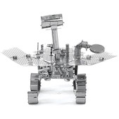
Good PBS Example (Velociraptor)

The System Block Diagram shows the outputs for the ports of the DC motors, Servo motors, and the input for external power. The LDO 5V Regulator is used to increase the 3Dot board output voltage to the operating voltage for the Servo Motors. An Android or iPhone device with an Arxterra App will be used to control the Biped.
Source Material:
Fall 2016 Biped – Updated System/Software Block Diagrams

By Mikaela Hess (Manufacturing and Design)

Pictured above is the initial idea that the Manufacturing engineers have designed. As can be seen above, we have the DC motors moving in the center of the body of the biped in order to have better control of the center of gravity. To make this happen, we must create a distance between the two DC motors large enough so that the two servos sized feet can be picked up and land onto the ground without disturbances. To go without the disturbances, we must create a distance of one servo between the DC motors, and an additional ⅕ of an inch of room to adjust for human error. Next, we placed the body on top of the DC motors, facing the other way in order to counteract the weight of the DC motors on either side, for better stability. This idea of having a long body was actually created from the Creative Project, where we forced a truck onto our biped design. The overall size of this Biped is to be under 10 inches. The body of the Biped is expected to be no more than 3 inches and the servo on the feet are expected to be no higher than 1 inch. With those calculations and the 1-inch radius in which the leg is designed to move around, the actual leg is to be designed in a total of 4-5 inches.

The actual walking of the biped is broken down into 5 steps here. In order to follow this design, the pictures are color coded according to the design’s components. In blue we have the representation of the circular path created by the DC motor and the pink segment. The pink segment is a sturdy piece of material that is directly linked to the DC motor and has a loose joint connection to the leg of the Biped, or the yellow piece in the picture above. Both legs start off in position one where the legs are bent and at rest at x and y equal zero on a radian circular graph. One leg then shifts its weight over by moving the leg over at an angle theta from resting position to the side by a servo. Once that is done, the DC motor then turns on and moves the pink segment to the negative pi over two positions on the same radial circular graph. This makes the body shift upward and lifts the other leg along with the body. After the segment goes to negative pi over two, it will move to pi on the radian graph, the ankle with resume its original position, causing the biped to take a step and then the legs will be programmed to reach equilibrium and resume its original position. Once that happens, the other leg repeats the same process and vice versa. Overall, the Biped should walk.
Once this design was created, I sent more photos and information to a Michael Oran Tobin, a Control Systems Engineer for California with PE Certification #CS7494. Once I had explained the servo use and parameters of the total design, it was made clear that my design would fail. What I failed to notice was the joint at the knee and the segment (yellow and pink where they connect), was that because there was no control onto that joint that the body could give out. As well, my design required precision that only DC motors with rotary encoding. A recommendation was made to use either a memory wire that straightens when current is given and loosens when there is none, or to use a servo at the knee for better control. The servo at the knee was decided to be a better option due to the memory wire being in early production and may not be able to handle the weight of the servo and leg. After going over the entire design, Michael Tobin strongly recommended doing more research on how humans walk and to consider how humans move their feet towards the center of gravity line to walk and then moves outward for better balance. As well, he suggested using a second wheel for better control of the joints. These pictures and ideas are pictured below and were made by Michael Tobin.


Overall, the design needs to reconfigured. More servos and research need to be done in order to create a working and walking Biped. The difficulty in this task is that most designs for biped are made using solely servos or stepper motors, which means this Biped leg design has to be made from scratch, but with help from other engineers and more research, it should be made possible. Also, a discussion with the project team and customer should be set up in the near future to discuss the use of more servos or motors.
By Phong Nguyen (Manufacturing and Design)
 This picture shows us a biped design based on human structure (hip, knees, and feet). As shown above, we decided to design the Biped with two DC motors for each hip, two servo motors for each ankle, and two Servo Motors for a turning movement. The DC motors are responsible for lifting up the whole leg while the servo motors will be used to shift the center of gravity. If we want to turn left or turn right, the servo motor at ankle will be able to accomplish that like last semesters biped. Under the foot, we will use high friction material such as sandpaper, rubber, or plastic.
http://robogames.net/symposium/2007/07-108-Vaidyanathan-AnnaUniv-AnalysisofBipedalWalkingRobot.pdf
http://embeddedprogrammer.blogspot.com/2012/08/simulation-of-humanoid-robot.html
By Abraham Falcon (Electronics and Control)
Biped Electronics and Control Design Process/Analysis
According to 3Dot Board specifications, it only supports 5V Turbo Boost for driving DC motors and for the Servo Motors to be operated at 5V. Using a rated 12V DC Motor to be power at 5V to measure the current draw at no load conditions and stall current to know the maximum current the motor will use to determine the Biped Battery total current it can supply. Also, for a Servo Motor to be power at 5V to measure no load current and stall current to determine the maximum current it will draw to know what battery is needed.
Biped Electronics and Control Tasks
Source Material:
Fall 2016 Biped – Updated Schematics
http://arxterra.com/goliath-fall-2016-preliminary-design-documentation/
By Mikaela Hess (Manufacturing and Design)
Manufacturing Tasks
Conducted by: Luis J. Martinez (Mission, Systems, and Test Engineer)
Battery (Duration, Powertrain)
As selected from our previous trade-off studies, the battery of choice for powering our Prosthetic Arm, in conjunction with the Prosthetic Hand, recognized as the Upper-Limb Prosthetic System was the 14.8V (4S), 1600–mAh Zippy Compact Lithium-Ion Polymer (LiPo) battery.
Incorporated into our system to fulfill the requirements for duration (L1-3) and powertrain (L2-7), associated tests were conducted in the verification and validation phase of the Prosthetic Arm system and are summarized as follow:
Duration (L1-3)
Following preliminary calculations calling for a 1500-mAh capacity, the battery was first charged to its full capacity through use of the Imax B6AC Professional Balance Charger/ Discharger in accordance with LiPo battery safety guidelines as referenced from a previous semester. Setting the charger to top off the LiPo cells at a maximum of 4.2V each, the battery was charged to a maximum voltage of 16.8V in 50:04 minutes.
Upon reaching its full charge, the battery was then set up in a configuration to discharge at a constant rate until the voltage dropped to 12V, a minimum voltage recommended by LiPo battery safety guidelines.
The duration test concluded in approximately 3 hours and 45 minutes, drawing an average of 0.317 Ah (amp-hours) during hour 1, 0.4 Ah during hours 2 and 3 each, and 0.3 Ah during the final 45 minutes, totaling to 1.417 Ah in capacity over the entire duration.
Based on a 3.2A total draw on 12V for the Upper-Limb Prosthetic System, where the Prosthetic Arm and Prosthetic Hand systems are estimated to draw 2A and 0.7 A on 12V, and 1A and 0.1A on 5V respectively, the test yield of 1.41A is considered passing due to the fact the Upper-Limb Prosthetic System will not be drawing a constant 3.2A during the entire 20 minute duration time.
Factors such as a two-digit significant figure on the current draw for the battery discharger, and given the battery was programmed to stop discharging upon reaching an overall 12V per precautionary guidelines to avoid permanent damage to the cells, the 1.417 Ah yield is conservative and considered to have enough head room to permit a 20 minute meal duration.
Powertrain (L2-7)
For the powertrain test, calculations were made indicative of a 3.43 ohm, 42 W load to test a 3.5A draw on 12V, and a 5 ohm, 5W load to test for a 1A draw on 5V. After powering our Printed Circuit Board (PCB) and connecting the 3.43 ohm load on 12V, with an in-series ammeter to measure current, a measured current draw of 3.056A were effectively verified drawn from the 12V source – this due only to the fact that a 42W resistor was not available, and our test was conducted with a 25W resistor instead. Afterwards, the load was swapped out to the 5 ohm power resistor corresponding to the 1A test. Respectively, this experiment yielded a measured current draw of 0.949A, effectively verifying the current draw from the 5V source. In conclusion, the powertrain test proved the capacity of the Prosthetic Arm system to deliver 3.5A on 12V and 1A on 5V respectively, should the Upper-Limb Prosthetic System need it.
Table of Contents
By Carolina Barrera
The objective of the Prosthetic Arm is to engineer and design an arm that will help position the hand in three-dimensional space. The arm should allow the hand to reach the mouth as well as the dinner table (tray) to allow the user to pick up food items from the table and back.
By Carolina Barrera
The arm in conjunction with the Hand group should allow a veteran amputee to complete an independent task as eating a Quarter Pounder meal by himself. The arm should be able to fit a long-sleeve tank/sweater that helps the discretion of the device.
By Luis Martinez
Final system requirements updated for the last demonstration include the custom PCB requirement per the criteria of Professor Hill, aesthetics, and noise. These specifications can be found at HERE in addition to the link ABOVE.
The system implements a MyoWare sensor that reads myoelectric signals from the bicep, and sends them to the MCU to control the up and down movement in the arm.
If you want to be directed to a specific topic in the system design documents use the links below. Click HERE to have access to the folder with all the 3D printed, and lasser-cut SolidWorks designs
by Luis Martinez
The system block diagram, depicting high-level block interactions between the electronic and controls subsystem responsible for supplying power, and managing sensory inputs, and the manufacturing subsystem, responsible for physical layout of the overall system structure, inclusive of the printed circuit board (PCB) can be found HERE.
by Fabian Suske
The blog post shows specifications the Electronics and Control Engineer accounted for when selecting the right motor for our project. The trade-off studies were done comparing a $500 motor and the one that we initially selected. However, this motor (Bipolar stepper with a 27:1 gearbox) was later replaced for a motor with the same specifications but a bigger gear ratio (100:1).
Trade-off studies for the motor can be found (HERE)
by Fabian Suske
The use of a battery was crucial for our design since portability and powertrain were two of our system requirements. The battery should supply enough power to both systems and meet a 20 minutes required duration.
Trade-off studies for the battery can be found (HERE)
by Luis Martinez
The updated interface definitions detailing interactions between the Teensy 3.2 microcontroller for the Prosthetic Arm, respective Myoware and temperature sensors, in addition to motor control and voltage regulating components can be found HERE.
by Forrest Pino
The design of the arm implements a bicep and integrated forearm design. The two pieces are mainly 3D printed, but they have a couple of laser-cut acrylic pieces. The bicep structure is meant to be a strong and sturdy structure that holds and lifts the forearm, the hand and less than 1 pound of additional weight. The forearm design was meant to be a lighter and less compact structure, but yet strong so it doesn’t break with the weight of the hand, while held by the bicep.
Also, a vest was developed as a holding mechanism of the arm in case the weight of the arm gets on the way of the EMG sensor. However, this far we can test without the vest.
There is a blog post regarding the development and evolution of the hardware design of the bicep. For more information, click HERE
Once the design was complete, a simulation was implemented in order to test the selected materials. The main pieces of the design were either printed with plastic filament or were cut from a sheet of acrylic that was purchased at a local hardware store. The printed pieces were made available by the division manager for manufacturing since he built and owned a 3D printer. The laser cut acrylic pieces were able to be accomplished because Professor Hill allowed access to a laser cutting machine. The designed pieces were constructed in a way that would allow them to fit together similar to puzzle pieces. These pieces would then be fastened together using nuts and bolts of various lengths and diameters depending on the available space surrounding the fastener holes. Since the utilized material is known, then a simulation can be constructed in order to simulate specific stresses and forces that a design may undergo. The simulation that was constructed for the bicep implemented stress under gravity and a 20 lb∙f at the axis where elbow rotation occurs. The 20 lb∙f was selected because the force exceeds what is required of our system and if capable, the design would be suitable for what is expected. In order to properly simulate the system, one must select various characteristics that would help mimic the system properly. Since fasteners were not constructed in the 3D modeling, bonded surfaces were implemented where the various parts touched each other. This allowed for the pieces to remain secured in position when undergoing external forces within the simulation. The top plate of the design was chosen to be the fixed surface in the simulation so that the simulation would more closely mimic the mounting of the arm in real life.
The image below highlights the areas in which the design experiences the most deformation due to the external forces that are applied. The blue areas experience the least change while the areas in red experience the most deformation. The image below seems to show that under the current forces, the design would not be able to sustain its structural integrity. Although, the deforming that occurs in the images are greatly exaggerated due to characteristics that were set for the test. In the images, one can see that the scale for the alterations is in microns. The actual deformations in the real life implementation would go unnoticed.
The image below illustrates the design from behind while highlighting the stress that is experienced inside. Internally, the area that experiences the most stress would be the bracket that supports the battery. Despite the fact that the battery support appears to be losing its shape, the changes that are experienced are less than a few microns.
The image below shows the design from the front. The force that was applied to the axis of rotation for the elbow was implemented to occur in a fashion that was normal to the interior face of the bored holes for the gear shaft. The slight curvature inward is due to the bored section that surrounds the holes meant for the gear shaft. These recessed sections were implemented so that mounting brackets for the gear shaft could be affixed slightly below the surfaces of the walls of the bicep.
Demoing the project became a challenge since the team was unable to come into contact with a volunteer that happened to have the amputation that would benefit the most from our design. Since an amputee would not be utilized, a plan was set so that the prosthetic arm could be displayed in a manner that would mimic its use by an amputee.
The image below illustrates the support system that would allow the prosthetic arm to be suspended in the air with minimal effort from the user. A camping/travel backpack was utilized for the support system and was modified to better fit the needs of the project. The actual pack of the backpack was removed since it did not serve any purpose to the project. The top bar of the backpack was removed and replaced with copper pipe. The copper pipe and couplers were donated by Chris Pino and the access to his tools allowed for the proper cuts and drills to be made. The side bars were shortened on the top and bottom so that the overall size could be reduced. Luckily, the copper pipe was about the same size as the pipe used in the pack which helped to make fitting easier. The soft metals that were utilized were easy for drills and allowed for set screws to be placed. The screws helped secure the modifications and kept the structural integrity intact.
The image below highlights the positioning of the prosthetic arm compared to the user. The backpack originally utilized a push-button mechanism that allowed the user to detach bar meant to help facilitate storage. The push-button mechanism was taken and implemented so that the pipes that facilitate position could be removed and vertical positioning could be selected based on the user. From the image below, one can see that drill holes were made and that a fastening pin from the backpack was used to aid in vertical positioning. An issue that was encountered was determining the lengths of the pipes that would hang over the shoulder. At this point, it was decided that further work would be done on the attachment of the arm before pipe lengths could be finalized.
The image below highlights the positioning of the prosthetic arm compared to the user. The backpack originally utilized a push-button mechanism that allowed the user to detach bar meant to help facilitate storage. The push-button mechanism was taken and implemented so that the pipes that facilitate position could be removed and vertical positioning could be selected based on the user. From the image below, one can see that drill holes were made and that a fastening pin from the backpack was used to aid in vertical positioning. An issue that was encountered was determining the lengths of the pipes that would hang over the shoulder. At this point, it was decided that further work would be done on the attachment of the arm before pipe lengths could be finalized.
Once the knee pad was in place, then proper pipe lengths could finalize. The image below shows the final outcome of the support system. The attachments that were used for securing the prosthetic arm to the support system were pneumatic tool couplings. The pneumatic tool pieces and their arrangement were beneficial to the design because their swivel actions helped to mimic the movements that occur in a shoulder and allowed for easy detachment.
The image below shows how a user would attach and demo the prosthetic arm. The pneumatic tool couplings would simulate shoulder movement while the kneepad attachment would help guide the prosthetic arm alongside the user’s arm.
by Fabian Suske
A blog post regarding the Codding of the Prosthetic Arm is available in HERE
by Luis Martinez
In consultation with the customer, various iterations of the program/ project (L1) and system/ subsystem (L2) requirements were enacted throughout the duration of the project in effort to avoid redundancies and reallocate resources towards specifications for mission success.
Program requirements addressing schedule, cost, and storage were satisfactorily met and can be found here.
by Luis Martinez
Final system requirements updated for the last demonstration include the custom PCB requirement per the criteria of Professor Hill, aesthetics, and noise. These specifications can be found at HERE in addition to the link ABOVE.
by Luis Martinez
Final subsystem requirements updated for the last demonstration include the specification for a 55 degrees Celsius activation setpoint for a temperature sensor safety feature, and the size specification to be a focus on a 35 cm +/- 5 cm length allocation from the elbow to the tip of the middle finger on the Upper-Limb-Prosthetic System. These specifications can be found HERE.
by Carolina Barrera
The WBS is found HERE
by Luis Martinez
Overall, power requirements were significantly lower than the petitioned allocation for 3.5A on 12V and 1A on 5V as evidenced HERE.
by Luis Martinez
In terms of mass, the Upper-Limb Prosthetic System measured in at 1.321 kg (2.912 lbs) from the elbow to the tip of the fingers in actuality, with theoretical summation of weights shown HERE . Overall, the system weighed in at 1.99 kg (4.39 lbs), with individual component weights referenced in the same link as above. Both systems complied within their respective mass limits.
by Carolina Barrera
By the end of the semester we were 1.42% under budget. However, there are items that we just eat the cost for. Many of them because the person that purchase didn’t keep a hold of them or just forgot to keep them.
Click HERE to look at our finalized cost report
MyoWare muscle sensor is thee sensor we are utilizing to read the myoelectric signals from the upper arm of the amputee so we are able to flex and extend the arm (perform vertical motion).
Electrodes are implemented with the EMG sensor so the user is able to stick the sensor to the bicep and read the Myoelectric signals from it.
Bipolar Stepper is the motor located at the elbow joint that will allow a +60 and -90 degrees of motion in the vertical axis. This motor should have enough torque as lo lift the weight generated by thee forearm, the hand and the heaviest food item of a Quarter Pound with Cheese meal
For the project it is necessary to have a Vest to hold the arm. This vest will help with the simulation of the system since will be mounted to someone’s torso. It should hold the arm parallel to the torso and also leave some space for the ideal placement of the sensor in the bicep.
The Battery is a Zippy Compact 35C Series 1600 with a Voltage of 18.5 V. The battery is crucial for the operation of the Upper-Limb Prosthetic System since it will be powering the motor in the arm, the EMC sensor and the Hand ‘s MCU, and components.
We bought a 3D Printing Filament (PLA) reel before we knew filament was going to be provided by the class’ instructor. This was not included to the estimated price nor to the actual price (30 is multiplying 0). We just added to keep accountancy in our group. In other words, we are not expecting to be reimbursed for this item.
The PCB is our finalized circuit layout in a board. We are in our first iteration of the board, but we prepared in case we needed to order a modified (fixed) board.
The IC small electronics are all the small components (capacitor, resistors, inductors, ICs and kill-switch) implemented in the manufacturing of the PCB
Miscellaneous Mechanical includes all the structural aesthetic components for the arm or the vest. This amount is allocated to vacuum form components that benefited the aesthetics, and mount of the project
By Carolina Barrera
The last update reported in schedule was CDR. In this report, it was shown that the “actual” line was starting to deviate from the “ideal” line. Meaning that we were getting behind in schedule with activities we were supposed to be doing, and we didn’t. Getting the PCB components, redesigning the forearm for integration and integration itself brought a few setbacks in our original design.
The next section shows our burn down diagram, and a brief description of pinpoint deadlines.
The burn-down shows is a good way to see the progress of the project, and the overall tasks during the semester. Time – counted in weeks, is along the horizontal axis, and the tasks are numbered, and added to be counted as completed on the vertical axis. The grey line is the “ideal” graph, which shows a uniform and constant completion of tasks during the given time. The yellow line shows the “actual” graph; the rate and actual items completed by the team in the time reflected. The numbers along these two lines are milestones along the progress of the project. For example, (1) corresponds to week 2, and is the week that the groups were assign. Little progress was done, but the group as a team was consolidated. (2) represents the research presentation on week 3. Studies were made to evaluate the best approach to complete the project. This involved planning, and minor advances in design; rough ideas. (3) is the Preliminary Design Review (PDR). (4) is Critical Design Review (CDR). (5) is the date the Arm and the Hand group scheduled as physical integration. However, no physical integration was accomplished by then. This is why the yellow lines grows slightly further from the grey line in this point. It should be made clear that even though integration didn’t happen, the two groups had independent advancements. We had our vest built, and our first PCB was almost finished.
Among the items pending after the final demo, and verification and validation were testing the integrated system, and generation of intangibles. Also, because of reasons beyond us, our MCU burnt on the day of the last demo, which didn’t give us an opportunity to demo our part on the entire system on the date of our final.
By Carolina Barrera
At the last phase of the development cycle of our project, we came up with aspects that could be improved in further iterations of the project. Challenges that include: the successful implementation of a kill switch as a safety feature of the arm, or trying to obtain the collaboration of an actual amputee for the project, or even trying to make a socket for the arm so it actually fits an amputee.
Future generations could take upon these challenges, and come up with improvement where we left off. The idea of documenting all these is that the generations to come use them as a baseline for their design. We might be able to shorten the path just a little, so they have a head-start in all this process.
As a team, we are very proud of what we accomplished. We learnt multiple aspects of the engineering method, experience the operational schema when working in an organizational matrix, and finally, we truly developed a more sophisticated use of our soft-skills. We hope our work helps you or inspire you. It is a beautiful process to see your ideas become tangible, and even more when they have the potential to help or impact a community.
Written by: Fabian Suske
Approved by: Carolina Barrera
Table of Contents
In order to fulfill mission success, the selected components need to brought to live. Therefore the MCU Teensy needed to be programmed.
The objective of the Code is to read the EMG sensor, the temperature sensor, the kill switch as well as moving the motor. Due the components chosen a variety of challenges needed to be addressed. The main challenge arises due to using a stepper motor in combination with the Allegro A4988 stepper motor driver. This combination needs constant signals from the MCU to the driver while moving. Therefore pulling of items like the kill switch or the temperature sensor are not possible. As a result Interrupt Service Routines (ISR) were used for almost everything.
The first ISR was used to read the EMG signals. Prototyping has shown that pulling this value, the way it is required, is not sufficient enough. The arm then reacts funny and junky. It also has a poor response time. Most of this results in the fact, that the user starts using the arm in the middle of the pulling process. As a result the long burst might be interpreted as short ones. Or short ones not at all.
This problems were solved once the ISR was implemented. If the user starts using the arm, the Teensy registers an interrupt at the assorted pin. Then the burst duration algorithm “kicks” in and delivers an accurate result.
The code to detect if the user operates the arm or if noise triggered the interrupt is as short as possible in order to not interrupt the movement of the arm.
The temperature sensor was another challenge. The way the sensor is designed to work as followed: After a few byte were written into registers on the sensor the sensors starts the temperature reading. Then the user has to wait at least 750ms (a little more is better) before the measurement can be read. If the user tries to read the measurement faster the senor either return one of his “default” values 0 or 85 or it simply returns the last measured value. If the value continuously is read to fast, the value displayed might be obsolete and wrong.
Waiting for 750ms on the other hand is not acceptable while the motor is running. An ISR that performs the reading in a smart way has been implemented:
The ISR will be handled by a timer object. Every time the timer has an overflow the ISR is triggered. Once the ISR is called it checks a flag to see if the sensor is currently reading a measurement or not. If the measurement is not in progress a measurement is started. Once the ISR is triggered the second time 800ms later the values are ready to be read.
In this way no time is wasted with a delay function.
The kill switch is handled in a similar fashion as the EMG sensor. In case the kill switch is triggered due to an external interrupt, the ISR then sends a low signal to the enable pin of the LDO which then shuts down the entire system.
The last part that’s needs to be coded is the motor control. The previously mentioned EMG-ISR has provided us with the direction of movement (Up, Down or Stop). The constantly called motor routine then moves the arm in the desired way.
In order to not violate our range of motion a few functions needed to be implemented additionally. The 150 degrees of freedom needed to be translated into degrees the motor actually travels. Once the position of the motor was found a routine checked if the desired motion is valid. If the motion is not valid, the arm travels the maximum possible distance.
In order to shut down the system once an unsafe operating temperature of 55°C is reached yet another ISR has been implemented. This ISR is also based on a timer. Once this ISR detects that the temperature is unsafe, the system is shut down in the same fashion as with the kill switch