By Ridwan Maassarani (Design and Manufacturing)
Approved by Inna Echual (Project Manager)
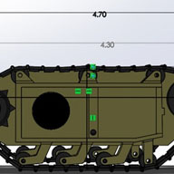
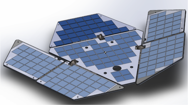
As a requirement, solar panels had to be manufactured that is of the same form factor as the spirit and opportunity mars rovers that were designed by NASA. To accomplish this, my team and I visited JPL and was able to find model at their museum. In addition, a small scale model was purchased from the gift shop for taking measurements later on if needed.

Figure 1: Small-Scale Model from JPL

Figure 2: High-Quality Rendering Photo (top view)
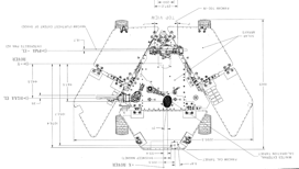
Figure 3: Spirit Rover Dimensionas
I was also able to obtain a schematic picture by contacting the same individual who made the high quality rendering pictures. Here’s is the website for more information: http://v5.nicksotiriadis.gr/mars-rover-project/
From all this information, I took measurements and a ratio of 10 was used based on the requirement that the panels needed to fit a 19-inch-wide cabinet and to the panels were scaled accordingly in SolidWorks using the scale feature.
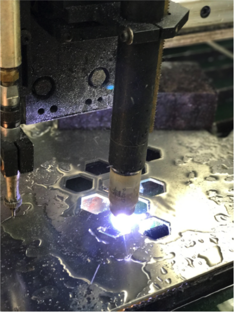
After the dimensions of the panels was established, a folding mechanism had to be devised to fulfill the cocooning state requirement. From my earlier blog post, I go over the various type of gears and types of mechanism that could perform a folding motion but utilizing worm gears for their high torque and self-locking feature was the best choice. First, torque needed to be transferred to the panels from the gears. The best option was to schedule an appointment with the mechanical design center and weld the rod to one leaf of the hinge. I tried to do this many times but failed since Electrical Engineering students do not normally get help from the mechanical center so there was no fluid was to get help. This forced the use of an epoxy called JB weld, used as a welding alternative for metals which by the end of the semester failed. In future 400D project, I hope the mechanical center will become a place where students can get their designs manufactured with ease. I have stablished some kind of relationship with Joe, the person who runs all the equipment such as welding, drilling, and plasma cutting. Here’s are my panels cut using their plasma cutter:

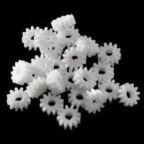
After making a connection from rod to panel, the gear needed to be attached firmly to the rod so that when the worm rod spins, torque is delivered to the gear, rod, and finally the panel. Ideally, metal gears need to have a press fit such as stepper motors in a printer. Press fitting gears is a science and there was no time nor the budget to get custom sized gears. So, a hollow rod was purchased from home depot and fitted in the gears bore to get a better fit from gear to rod as well as from worm rod to stepper shaft. The gears came with a set screw; this was used to secure the gears further. Since this is not the best method of connecting these gears, epoxy was used again for safe measure. For the next semester, I would recommend researching how to securely connect the gear to the shaft, rod to hinge, and worm rod to stepper shaft. Another improvement would be to make a gear box for these gears, this will serve as an encasement as well as a place to fill grease so that they are always lubed. Having lubed gears will prevent any friction between the teeth, it is crucial for metal gears.
In conclusion, another improvement would be to limit the amount of freedom the hinge has when unfolded. This can be done by welding some metal between the main panel and the right panel, this will help when the rover is being operated at the same time the panels are installed. It will remove the additional torque generated when the rover is being operated.
By Ridwan Maassarani (Design and Manufacturing)
Approved by Inna Echual (Project Manager)
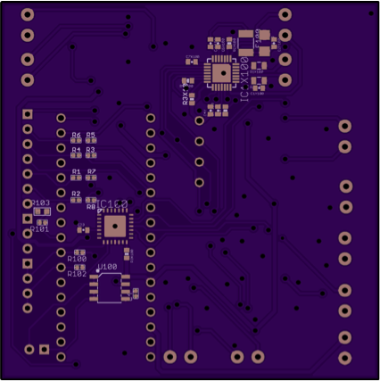
A custom PCB that can drive five stepper motors was needed to reduce the footprint on the rover. The custom PCB would also cut down on cost since stepper motor drivers that can run 3 or more motors can gen expensive. It was also difficult to find a motor driver than can run five motors. So, a custom PCB was made based on the A4988 stepper motor drivers capable of driving two coils.


By Gifty Sackey (Mission, Systems, Systems Engineer)
Approved by:
– Lam Nguyen (Project Manager)
– James Lee (Division Manager for Mission, Systems, and Test
Table of Contents
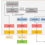
In this current block post, the interface matrix along with the eagle card documents have been provided and discussed in order to allow future 400D students to have a smooth transition when building upon the robot. The interface matrix excel document was designed based off the EAGLE CAD design which was designed by my groups electronics engineer. The EAGLE CAD allows us to have an idea of what our PCB will look like before actually printing it. With the help of this computer software, tracing the design is not tedious because we are able to see the components that are used and their respective wire connections. For the diagram below, the components are placed in columns and have their connections to the 3DoT board listed in each row section by the pin name. For instance with our GPIO expander, we notice that the SCL is connected through the IC1-12 pin while the SCA pin is connected at the IC1-13 to the GPIO expander.
Matrix Interface Link: interface-definition
Along with the interface matrix, each project group is required to design a cable tree diagram which is another visual presentation of the system block diagram but with more details regarding the connection types; the wire lengths and also the gauge sizes. The cable tree diagram that has been provided below is based on the system block diagram and follows the same format and layout. This diagram was made possible through draw.io which served as the tool to design our diagram.
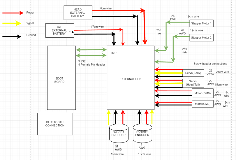
Diagram 1: Cable Tree
These diagrams that have posted above in this current blog post are the cabling diagram and interface diagrams. Both of these documents from above were previously presented during our presentation for the critical design review. Subsequently they have been revised to ensure that the velociraptor group produces excellent documentation materials.
[1] https://drive.google.com/file/d/0BzIcuzRpcmk4S252NEc5Sld5MU0/view
By Gifty Sackey (Mission, Systems, and Test)
Approved by:
– Lam Nguyen (Project Manager)
– James Lee (Division Manager for Mission, System, and Test)
Table of Contents
The purpose of this blog post is to discuss and summarize the control functions that will be required in the programming of the robot. It will cover the software block diagram and introduce the set of tasks that the software had to accomplish. For the mission profile for the Velociraptor shall participate in the Game Arena and statically walk. The software flow chart that is attached, allows users to see how the Arxterra firmware will be modified and the programmed through the 3DoT board.
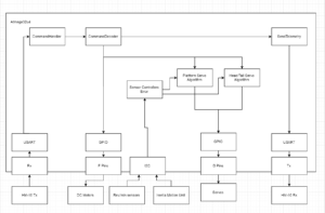
Diagram 1. Software Block Diagram
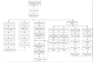
Diagram 2. Software Block Diagram Updated
In the event that a command is sent via Bluetooth from the ArxRobot App, the command decoder and handler functions will be executed on the action. The software block diagram, allows readers to gain an insight on the inputs that the robot functions will be taking as well as the outputs. For this blog post, I will be explaining in detail how the velociraptor will perform when the right motor is the only thing allowed to move. When the velociraptor is being moved and controlled by a single motor, the velociraptor is making a turn. In the case of the right motor moving, this indicates that the velociraptor is turning left. A turning left subroutine code would then be initiated as well as servo commands. In order for the velociraptor to be able to make a complete turn, it would have to shift its center of gravity over the left leg by moving the servo 30 degrees from the neutral position so that the it is balanced over that specified foot.
For the velociraptor to achieve static walking, the control codes will be designed such that both motors will be moving out of sync. While both motors are moving out of sync, as engineers, we need to make sure that the revolutions per minute (rpm) should have different values for both motors while having both legs be 180 degrees apart. The servo would then be moved over the left leg but then both motors would be required to move 180 degrees at the same rpm value and then stop in order to complete a step. At this point, the velociraptor needs to maintain balance so it needs to shift the servos at a 60 degree angle in order to ensure the center of gravity is on the right leg. At this point, the robot must move both motors 180 degrees forward to complete a step. The robot would then repeat this process until a different command is called from the Arxterra application.

By:
– Lam Nguyen (Project Manager – Velociraptor Wednesday)
– Paul Ahumada (Project Manager – Velociraptor Thursday)
– Gifty Sackey (Mission, System, and Test Engineer)
The final validation and verification test plan was written to verify the requirements for the Velociraptor through the Validation and Verification Matrix.
Link: verification-and-validation-matrix
Below are the validation and verification test plan that supports our level 1 and 2 requirements.