By: Lam Nguyen (Project Manager)
Hal Vongsahom (System Engineer)
Taylor Farr (Controls Engineer)
Aaron Choi (Manufacture Engineer)
Program Objective
Lam Nguyen (Project Manager)
The Fall 2016 Velociraptor is inspired by both the biped Titrus-III robot and the Theo Jansen biped robot. The Titrus-III was developed by the Tokyo Institute of Technology and the Theo Jansen biped robot was designed by the Gakken company. The objective for this year’s project is to avoid utilizing servos by implementing alternative motors to meet the customer’s demand. The most compatiable design for using alternative motors is the Theo Jansen biped robot known to model human giat motion that utlize continuous rotion with linkages.
Mission Profile
Lam Nguyen (Project Manager)
The Fall 2016 Velociraptor had the wonderful opportunity to be included in this years Game Arena called “Save the Humans”. Representing the dromaeosauridae theropod dinosaur from the Cretaceous period the fall the the Velociraptor will navigate through the game arena terrain and hunt down the Biped robot before reaching the safe-haven zone in a time duration of 30 minutes.
The Fall 2016 Velociraptor will demonstrate its navigation cabablities by operating telerobotically from the Arxterra control panel. With a fixed view of the game arena the Velociraptor will navigate through both flat surfaces and uneven surfaces such as linoleum and cardboard.
Requirements
Program Level 1 Requirements
Lam Nguyen (Project Manager)
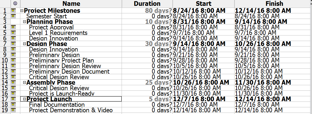
- According to the CSULB Fall 2016 Academic Calender, the Velociraptor biped robot shall be tested by Wednesday, December 14, 2016, the last day of EE400D [1].
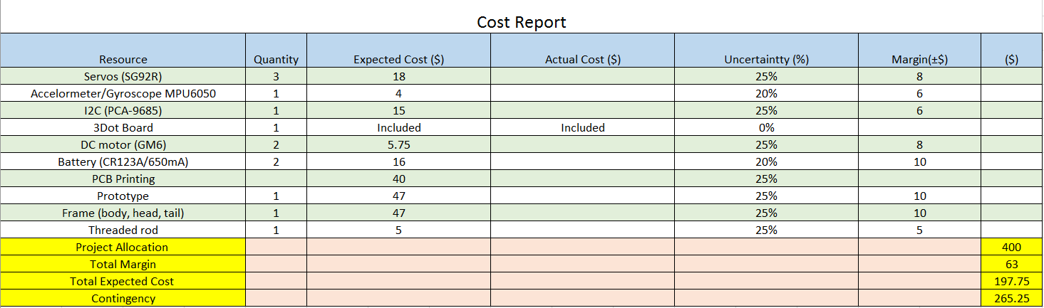
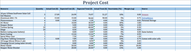
- The Fall 2016 Velociraptor biped robot budget shall be a limit of $400.00 [2].
- The Fall 2016 Velociraptor biped robot shall participate in the game “Save the Humans” defined by the game committee. [3]
Project Level 1 Requirements
Lam Nguyen (Project Manager)
- The Velociraptor biped robot shall resemble dromaeosauridae theropod dinosaur from the Cretaceous period. [4]
- The Velociraptor shall be able to statically walk on the terrains of the game arena.
- The Velociraptor shall be able to dynamically walk on the terrains of the game arena.
- The Velociraptor shall use Bluetooth communication with the Arxterra Android or Iphone application.
- The Velociraptor shall use a 3DoT board with a custom I2C shield.
- The Velociraptor shall navigate through the game arena’s terrain.
- The Velociraptor shall use a portable power source for the duration of the game “Save the Human”.
References
[1] Time, B. C. (n.d.). Final Exam Fall 2016 Schedule Charts. Retrieved September 21, 2016, from http://web.csulb.edu/depts/enrollment/registration/final_exam/fall_chart.html
[2] Khoivu0814. (2016). Retrieved September 21, 2016, from https://www.arxterra.com/spring-2016-velociraptor-preliminary-project-plan/
[3] Index of /~hill/ee400d. (n.d.). Retrieved September 21, 2016, from http://web.csulb.edu/~hill/ee400d/F’16%20Project%20Objectives%20and%20Mission%20Profile.pdf
[4] Dromaeosauridae. (n.d.). Retrieved September 21, 2016, from https://en.wikipedia.org/wiki/Dromaeosauridae
System/Subsystem Requirements
Project Level 2 Requirements – System Requirements
Lam Nguyen (Project Manager)
Hal Vongsahom (System Engineer)
Taylor Farr (Controls Engineer)
Aaron Choi (Manufacture Engineer)
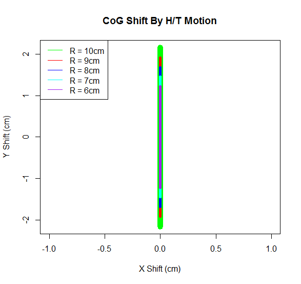
- The Velociraptor shall walk on two feet and use both head and tail to control the robot’s center of gravity.
- The Velociraptor shall implement the head and tail to shift it’s center of gravity on one foot in order to statically walk in the game arena’s terrain.
- The Velociraptor shall use an accelerometer and a gyroscope to detect its reference to x, y, z space to adjust it’s center of gravity to dynamically walk in the game arena’s terrain.
- The Velociraptor shall use an HC-06 Bluetooth to communicated with the Arxterra Application to control the robot’s movement.
- The 3DoT board shall receive commands from the HC-06 Bluetooth and decode the command data, and transmit the command data to the I2C to control the actuators.
- The Velociraptor shall provide a lithium polymer battery to provide power for the duration of 30minutes from the game objective.
- The Velociraptor shall be able to travel up an incline/decline slope no larger than 6.5 degrees.
- In order to navigate around the game arena’s terrain the Velociraptor shall travel on cardbaord and class room floor, uneven surfaces of the terrain shall be no larger than 0.5 cm.
Subsystem Level 2 Requirement
Taylor Farr (Elecontrics Engineer)
- In order for the velociraptor to be able to operate properly, an input and output system must be designed. For our inputs, we will be using a digital accelerometer to measure acceleration as well as a gyroscope to determine the position from a neutral point at any given time. [1] & [4]
- The accelerometer shall be digital in order to reduce coding(Help from Hal). Trade-off studies shall be conducted in order to find an appropriate accelerometer that is compatible with Arduino. [1]
- For actuators, motors shall be use to move the Velociraptor forward and performing actions in order to keep it stable. [2]
- Servos shall be implemented in the head and tail to move the head and tail to shift the center of mass 30 degrees in either direction. In order to correlate the sensors and actuators, a microprocessor is required to interpret the data at input pins and then provide the appropriate signals to the output pins in order to activate the motors and servos. [2]
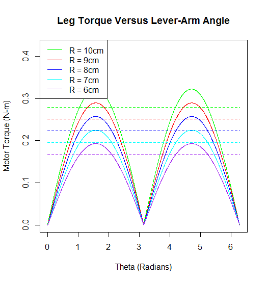
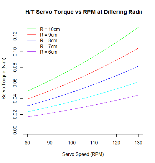
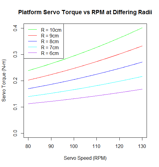
- The motors for the legs shall provide enough torque to support the 900 grams. Operating speed shall be determined by how fast the velociraptor needs to move in order to control its dynamic walk. The torque necessary to move the robot and support the 900 grams must be taken into consideration. This calls for a trade-off study of motors and servos in order to pick the appropriate ones. [3]
- Based on the speed and torque required, trade off studies shall be conducted to find an appropriate power supply that supplies enough current at the appropriate voltage.
- Fritzing diagrams shall be utilized in order to map out circuits connected to Arduino that provide appropriate and accurate data. Once this has been established, we will model the electronics in LT Spice, send the circuits to Eagle, and then design the PCB.
Aaron Choi (Manufacturer Engineer)
- In order to meet the customer’s demand in alternative motors the Velociraptor shall use the Theo Jansen Biped robot’s linkages for continuous movement. [5]
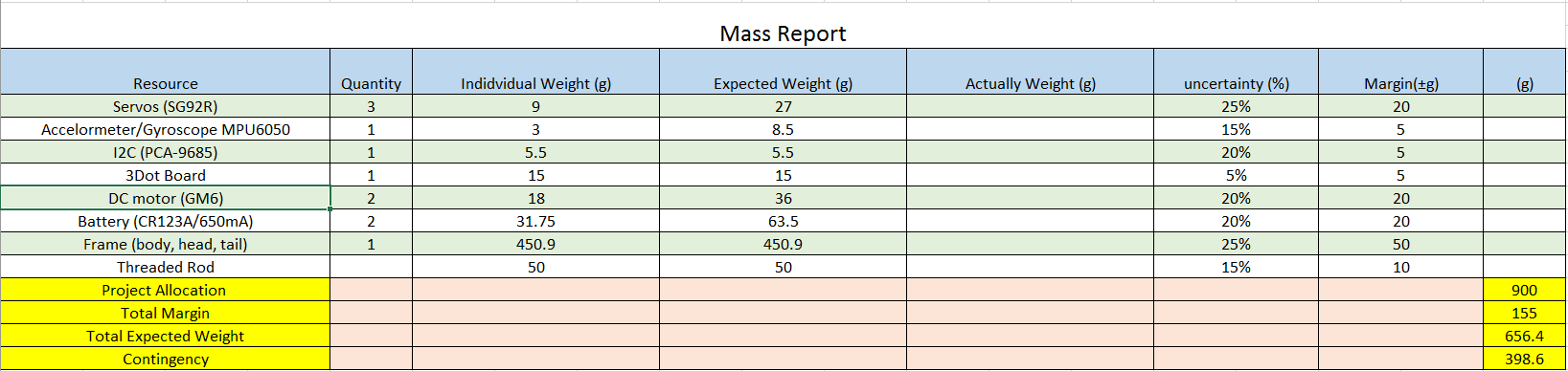
- In order for the Velociraptor to operate the mass shall not surpass 1000 grams.
References
[1] MAV-blog. (n.d.). Retrieved September 21, 2016, from http://tom.pycke.be/mav/69/accelerometer-to-attitude
[2] @. (2014). How a Robot Can Keep Its Balance and Stand up Even if it Gets Kicked – Case Study – Smashing Robotics. Retrieved September 21, 2016, from http://www.smashingrobotics.com/how-a-robot-can-keep-its-balance-and-stand-up-even-if-it-get-kicked-case-study/
[3] http://www.robotshop.com/en/gear-motors.html
[4] MAV-blog. (n.d.). Retrieved September 21, 2016, from http://tom.pycke.be/mav/70/gyroscope-to-roll-pitch-and-yaw
[5] @. (n.d.). Theo Jansen-style Biped Robot kit by Gakken. Retrieved September 21, 2016, from https://www.adafruit.com/product/1841
Design Innovation
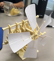
The team worked off of the creativity presentation, with ideas bouncing back and forth we considered additional problems and applied our research to find a solution. One of the main problems we have considered are the motors which provides a continous rotion for our Velociraptor. Since the customer demands motors instead of servos, that effects the design of the legs as well. For a model to follow we bought a Theo Jansen Biped Robot for further study of the linkages for the legs. We will create a design for the legs and chassis that with less amount of material as possible for prototyping.
Creativity Presentation
Creativity Presentation PowerPoint
System/Subsystem Design
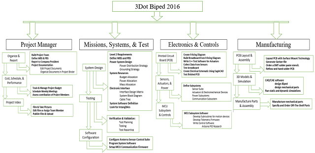
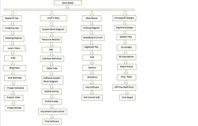
Product Breakdown Structure
Hal Vongsahom (System Engineer)
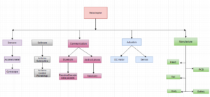
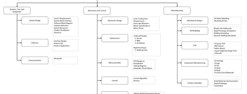
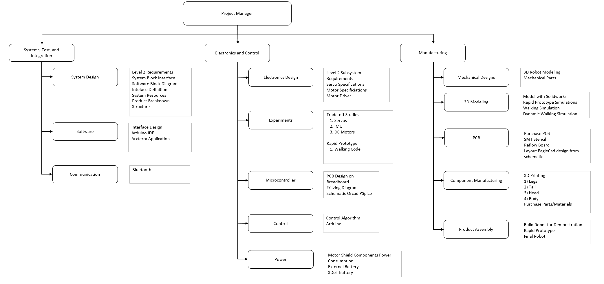
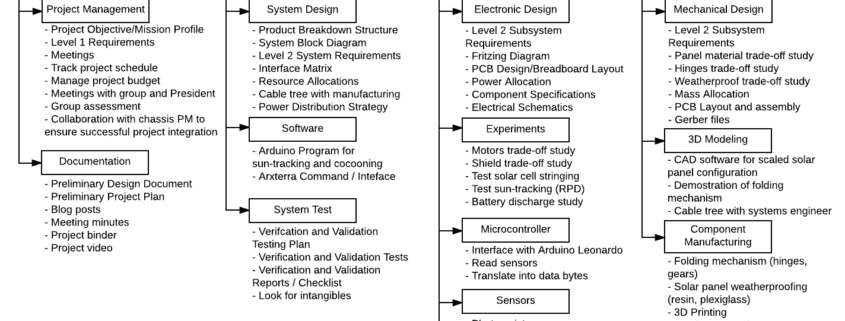
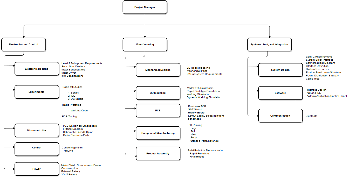
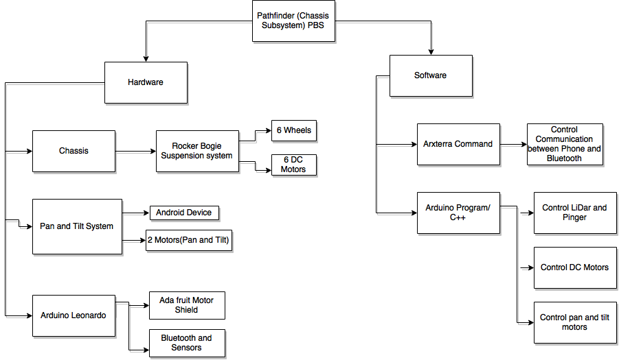
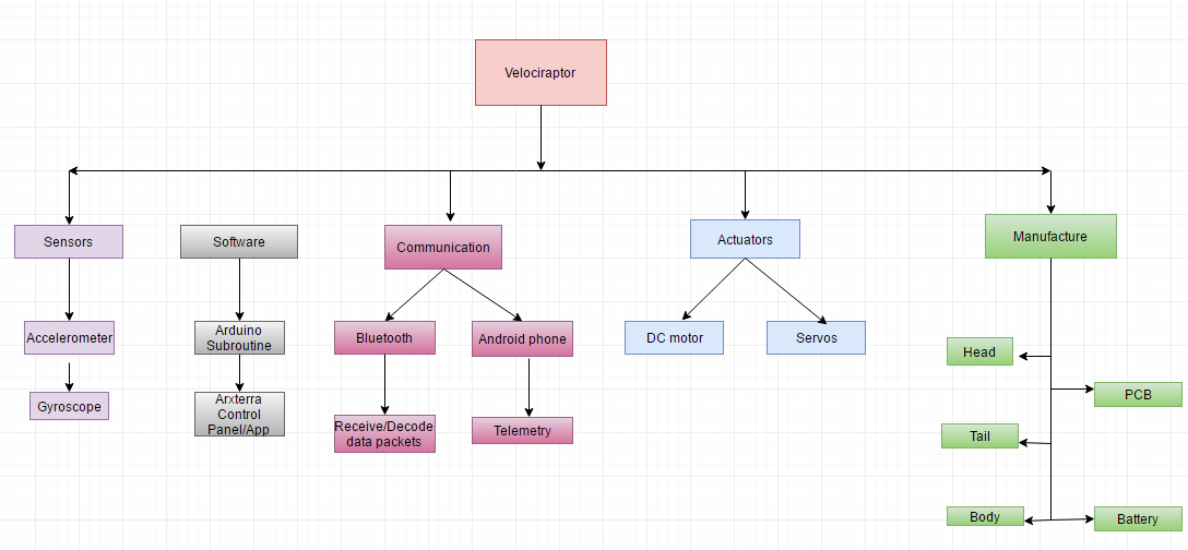
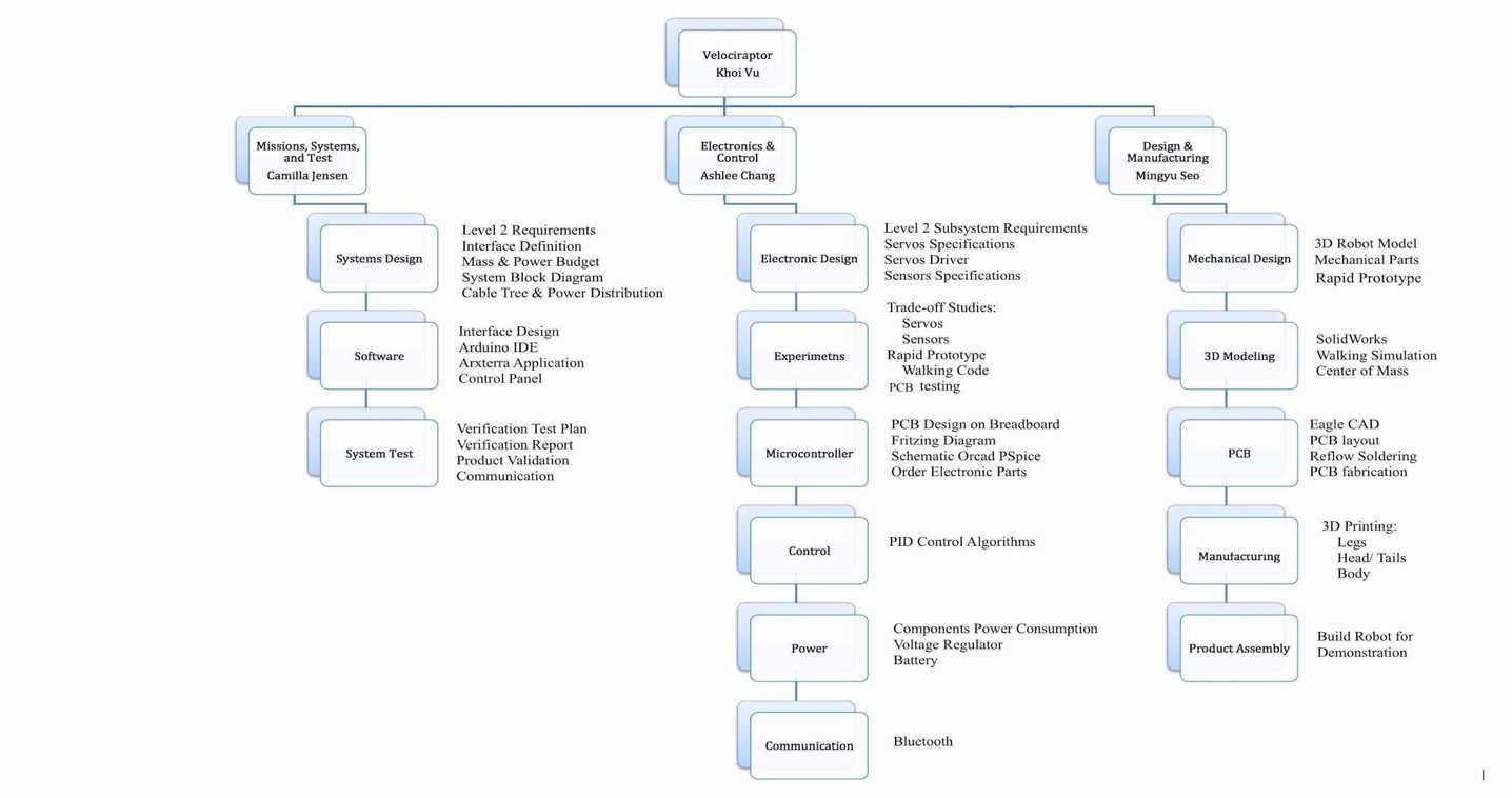
Figure 1
The image display on Figure 1. the product breakdown structure. This is a high overview of the structure flowing from the top down to the structure and component of the velociraptor.
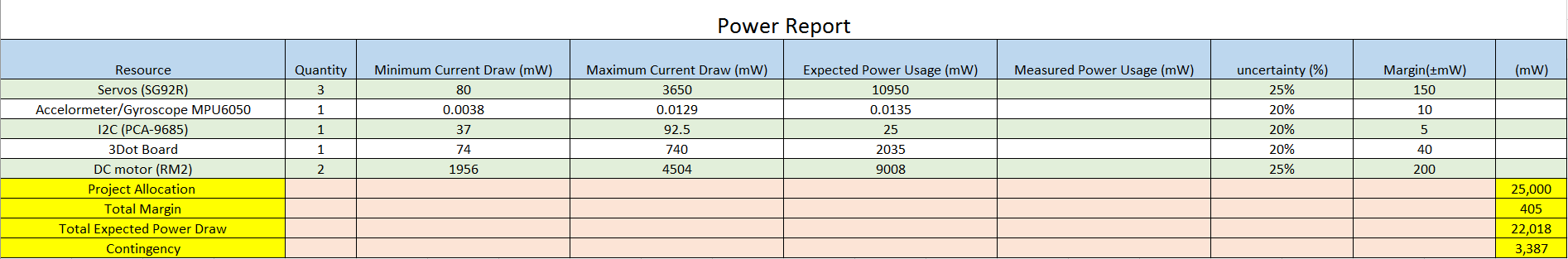
Power
The velociraptor shall be power by a portable supply source. The battery will power the systems 3Dot board, I2C, DC motors, Servos, and the Accelerometer/Gyroscope. This can be thought of as the food and energy necessary for the velociraptor to move.
Software
The software required by the customer is the Arxterra app. The Arxterra acts as a friendly user interface that will help control the movement of the velociraptor. The codes will be written in C++ in Arduino. All of the subroutine will be develop to properly control the movements of the velociraptor.
Communication
The main component to the velociraptor communicating properly is dependent on the Bluetooth. The Bluetooth will receive data packets that must be decoded. The Bluetooth will receive data from the Android phone.
Actuators
The actuators for our system are DC motor and Servos. The DC motor will control the legs to perform walking. The servos will govern the head and tail movement for the velociraptor. Another conceptual way to think of the actuators are it is the muscle of our systems.
Manufacture
This can be considered the bones, and the entire body of our system. The manufacture of the velociraptor head, tail, and body will be printed and constructed. The PCB will also be design and printed out to form the blood vessels of the velociraptor.
Reasoning
The customer requires our velociraptor navigate through the game arena with different surfaces and inclines/declines. Therefore, it is important for the design to incorporate as many DC motors or Servos to not restrict movement of the velociraptor.
Electronic System Design
System Block Diagram
Hal Vongsahom (System Engineer)
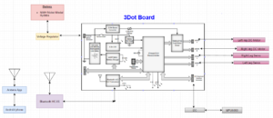
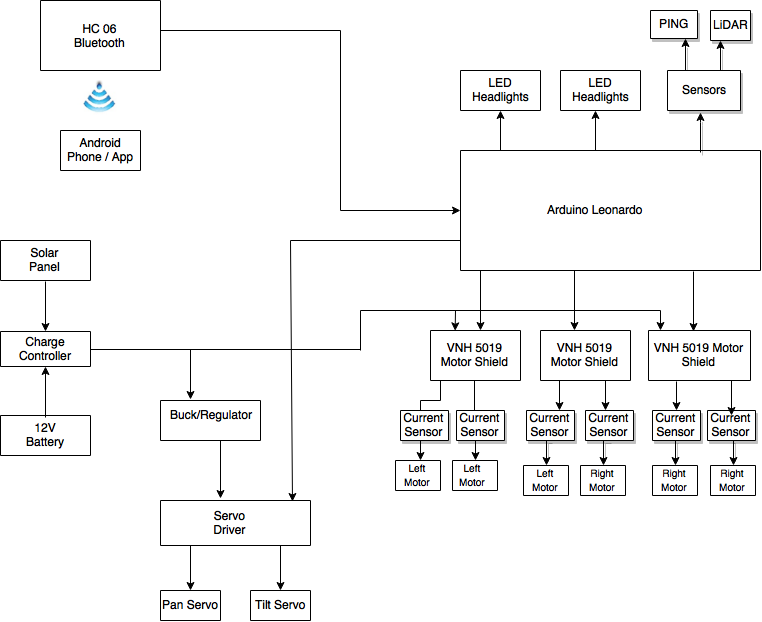
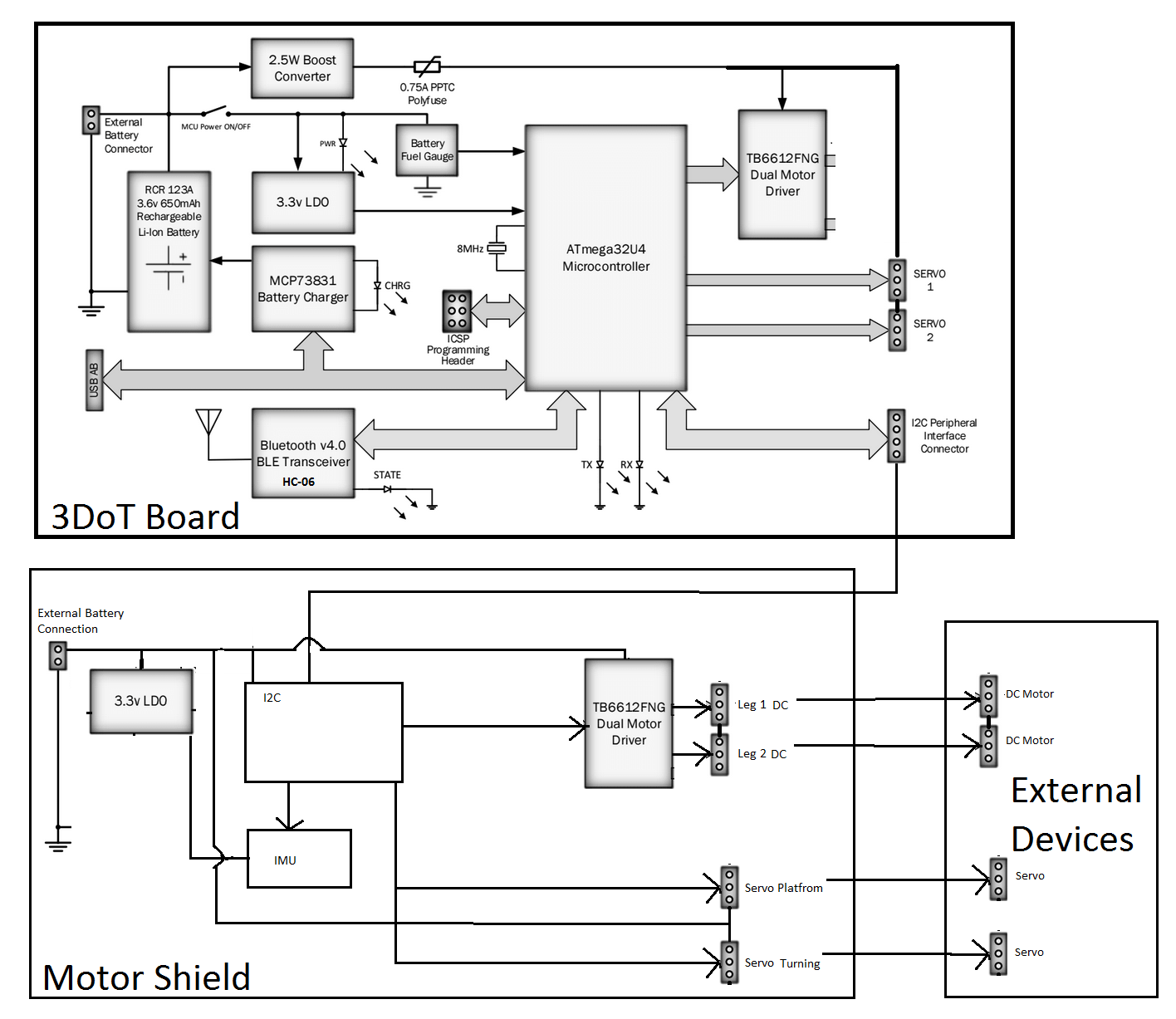
Figure 2
A system block diagram above shows the corresponding inputs, power, extended peripheral, outputs, and communication devices that will be use on this project. The image shows the input devices that will be sending data to the microcontroller will be the accelerometer and the wireless Bluetooth device. The communication that will contribute to controlling the velociraptor movement will be the Android phone and the Arxterra application. The portable battery device will power both the microcontroller, the I2C, and the outputs such as DC motors and Servos. This system diagram illustrates the important of the microcontroller acting as the brain for all other components to operate properly.
Interface Definition
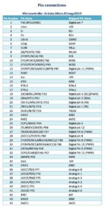
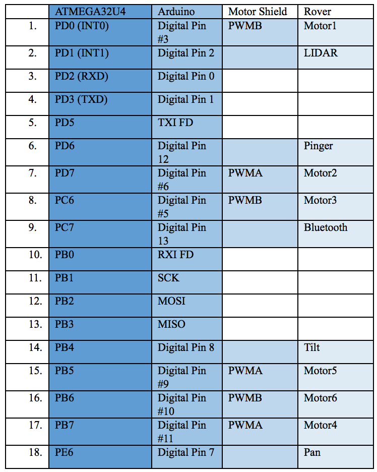
Figure 3

Figure 4
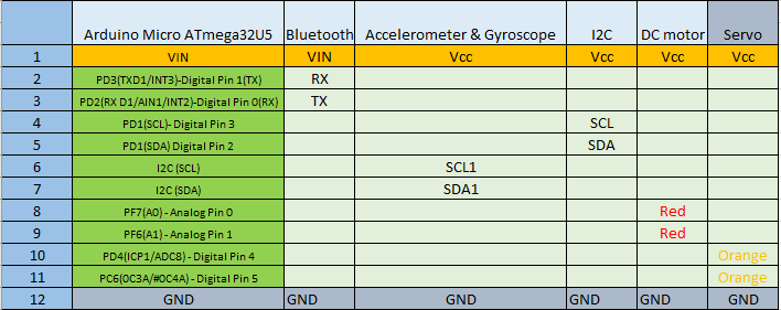
The above image in Figure 4 below lists all the pins in the Arduino microcontroller. It also gives a clear understanding of how much digital pins and analog pins are on the microcontroller. This can then lead to us designate each pin to control the devices needed for the velociraptor to operate successfully.
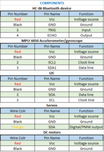
Figure 5
Pins for the velociraptor in the above image
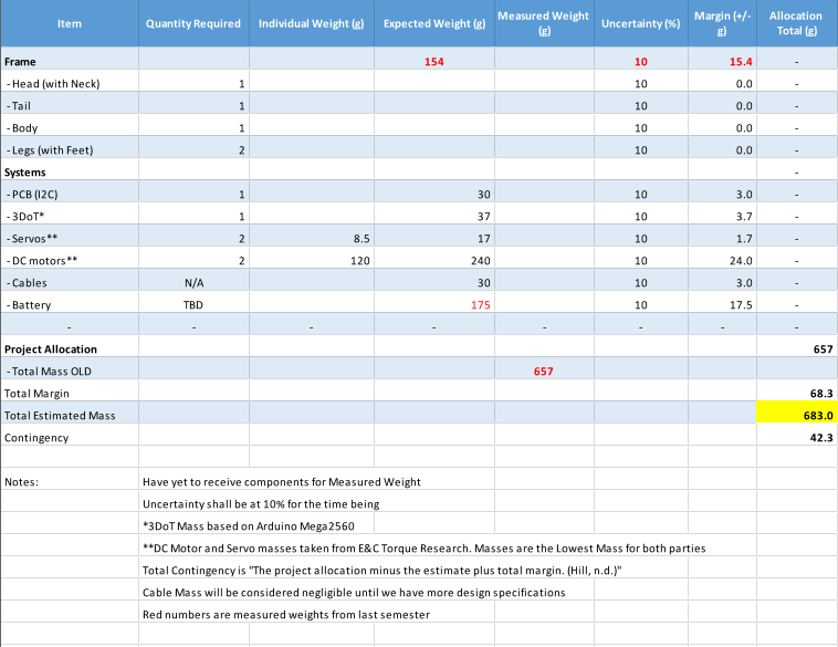
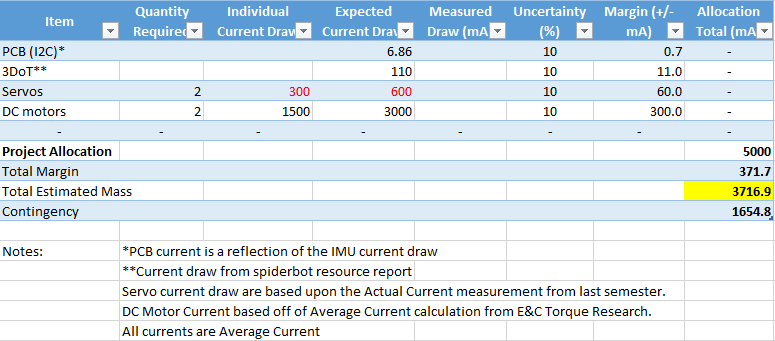
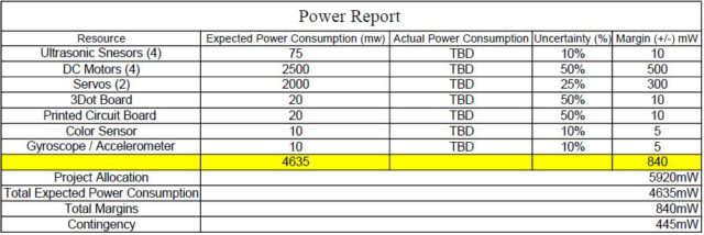
System Resource Map
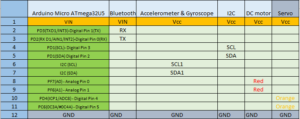
Figure 6
The table above list the system resource. A new requirement this semester from the customer is that we are required to have an I2C board. The 3Dot board is utilizing an Arduino Leonardo and the pins for SCL (Clock line) and SDA (Data line) are limited to one each. Therefore, we extend the SCL and SDA with the I2C board to connect the MPU-6050 accelerometer/gyroscope.
In addition, the primary design for our velociraptor will be using 2 DC motors and 2 servos. The DC motors only require a Vcc and Gnd, and the servos require PWM. If our design requires more DC motor or Servo we can add this on the 3Dot board pins or the I2C board. This will overall give us more flexibility.
Resources
[1] https://github.com/Bouni/Arduino-Pinout & https://www.arxterra.com/spring-2016-velociraptor-preliminary-design-document/
Mechanical System Design
Taylor Farr (Elecontrics Engineer), Hal Vongsahom (System Engineer), & Aaron Choi (Manufacturer Engineer)
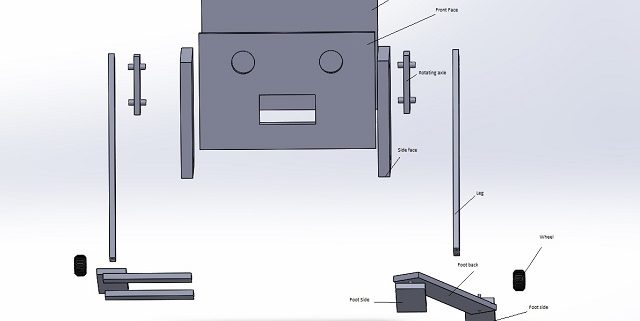
Leg Design
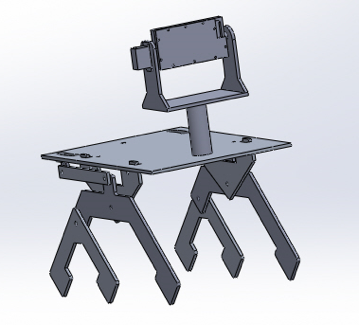
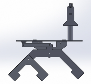
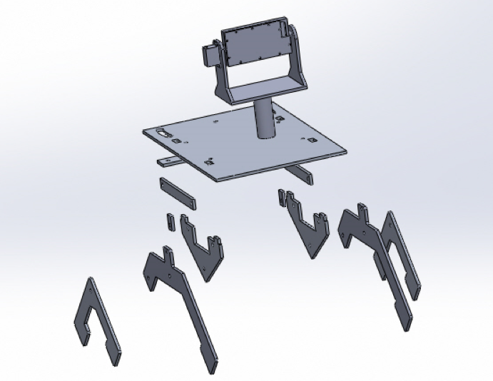
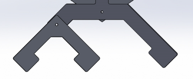
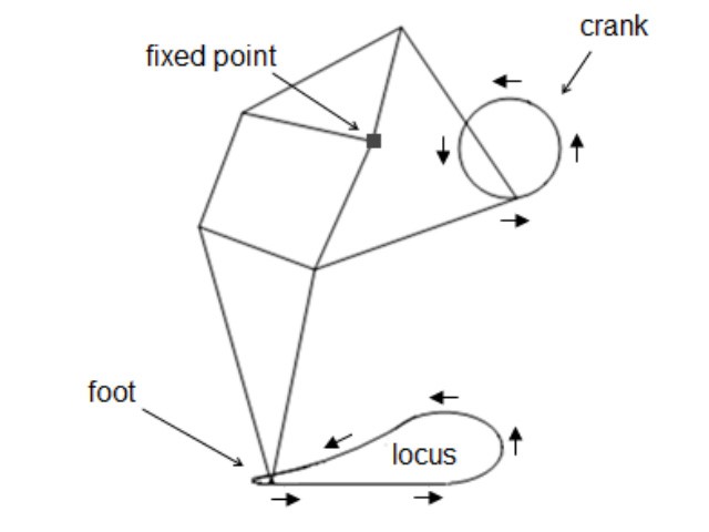
Previous generations of the Velociraptor utilized servos in the leg design. The controlled angle of rotation from the servos allowed the Velociraptor to walk statically. However, due to the customer’s demands, servos are not to be implemented within the leg design. Therefore, the Velociraptor shall utilize a DC motor. Since the DC motor use a continuous rotation, the Jansen’s Linkage shall be implemented with the leg design. The Jansen’s Linkage utilizes a joint to be driven by a continuous rotational motion.
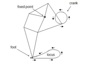
Figure 3
In the Figure 3 above, the leg mechanism models a Jansen’s linkage. This system utilizes a fixed point and a rotating point to model the human walking gait.
Resources
[1] AMANDA GHASSAEI: HOME. (n.d.). Retrieved September 21, 2016, from http://www.amandaghassaei.com/files/thesis.pdf
[2] What’s The Difference Between DC, Servo & Stepper Motors? (2015). Retrieved September 21, 2016, from https://www.modmypi.com/blog/whats-the-difference-between-dc-servo-stepper-motors
Design and Unique Task Description
Taylor Farr (Elecontrics Engineer)
The previous semester was unsuccessful with dynamic walking due to their sensors. They used an analog accelerometer to measure walking up inclines, and the previous semester did not use a gyroscope. The problem with analog is the converted codes will have tons of lines of codes. Therefore, compile too much memory on the Arduino Leonardo. In addition, there sensors was not accurate because they did not use a gyroscope. Therefore, this semester we are using a gyroscope in our system. This can monitor the displacement of the body from the neutral balance state, and update in real time. Moreover, we will use a digital accelerometer and gyroscope so that the coding will be simpler thus speeding up the processing time.
Sensor Selection
We have selected the MPU0605 as the gyro/accelerometer. The reason we choose this particular device as a sensor is it has both the features of an accelerometer and gyroscope. It also has an analog to digital converter built in.
Motor Selection
Once the sensor has been selected, the next task is to select the appropriate DC motors for the legs. Some options are brushless, brushed, shunt, series, or stepper. From these options, we will conduct trade off studies. Based off these studies, we will select the appropriate motors and servos that satisfy the torque and speed needed based on weight requirements.
Power supply selection
Now that the motors have been determined, we will select the appropriate power supply based on the power consumption of the selected motors. Based on requirements, we will use lithium ion batteries.
Aaron Choi (Manufacturer Engineer)
- Project level 1 requirements describe the velocraiptor to statically and dynamically walk. To improve the walking motion, the feet of the Velocraiptor shall implement a toe joint. This toe joint enhances performance and stability of biped robots [1], specifically increasing walking speed [2] and reducing energy consumption compared to a flat foot [3]
Resources
[1] Kwon, SangJoo, and Jinhee Park. “Kinesiology-Based Robot Foot Design for Human-Like Walking.” International Journal of Advanced Robotic Systems 9 (2012).http://cdn.intechopen.com/pdfs-wm/41665.pdf
[2] Ouezdou, Fathi Ben, Samer Alfayad, and Bachar Almasri. “Comparison of several kinds of feet for humanoid robot.” 5th IEEE-RAS International Conference on Humanoid Robots, 2005.. IEEE, 2005. http://ieeexplore.ieee.org/document/1573556/?arnumber=1573556
[3] Sellaouti, Ramzi, et al. “Faster and smoother walking of humanoid HRP-2 with passive toe joints.” 2006 IEEE/RSJ International Conference on Intelligent Robots and Systems. IEEE, 2006. http://ieeexplore.ieee.org/document/4059197/?arnumber=4059197


![[7]](https://www.arxterra.com/wp-content/uploads/2016/04/Final-cost-report-copy-2.jpg)