RC Control Spring 2016

Posted by: Luis Valdivia(Project Manager)
Written by: Kevin Nguyen(Electronics and Controls)


Table of Contents:
– Introduction
– Transmitter and Receiver
– Setting up the MultiWii
– MultiWii GUI
– Arming and Disarming


Introduction:
Being able to use the RC controller early on in this project will be very beneficial since it will make testing safer and more efficient. Since EDF’s spin at very high rpms, it is not a good idea to keep your hands on the quadcopter while testing. The RC controller will allow you to test the quadcopter at a safe distance. An added benefit to using the RC controller is that it doesn’t add that much weight to your system. All that is needed for the quad to communicate with the controller is the receiver. This blog will guide you through setting up RC control.


Transmitter and Receiver:
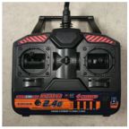
The RC controller that we used is the HK-T4A V2. This comes with a transmitter and a receiver. Most likely, you will be using the same controller as us so they would already be binded, but if not, follow this video to bind your devices. The transmitter will be from the remote controller. It will send a 2.4Ghz signal to the receiver on the MultiWii. The RC signal is much more reliable than bluetooth and is capable of transmitting at much further distances.
The transmitter controls the throttle, yaw, pitch, and roll of the quadcopter. The left joystick controls the throttle and the yaw; Vertical direction controls the throttle, horizontal direction controls the yaw. The right joystick controls the pitch and the roll; Vertical direction controls the pitch, horizontal direction controls the roll.

rc controller


Fig 1.1 RC Controller

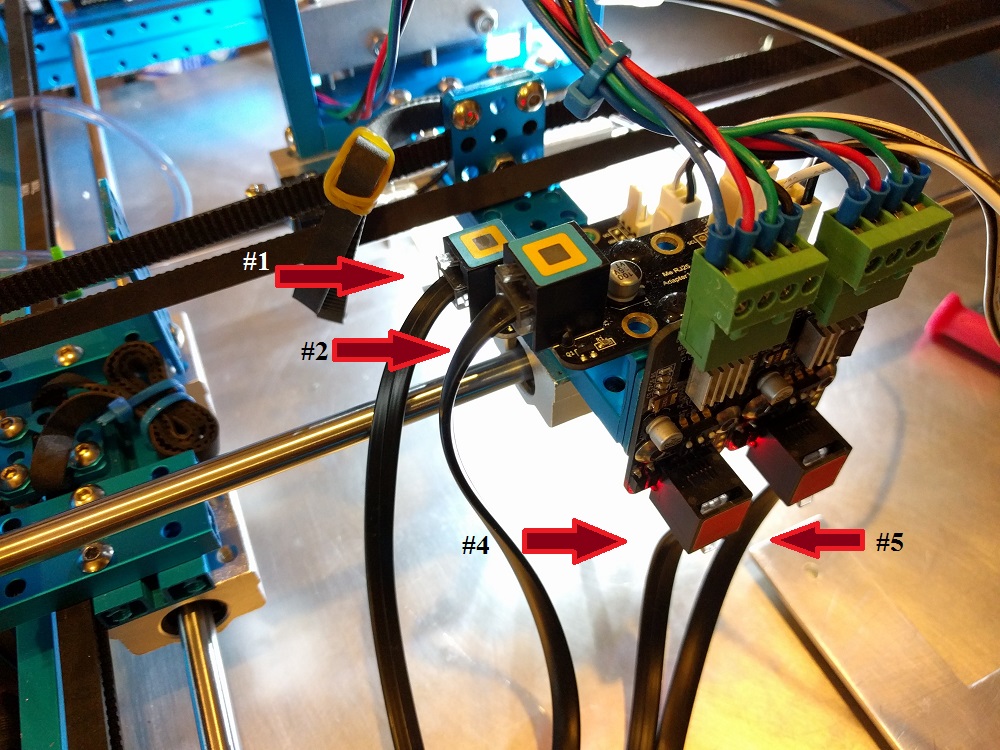
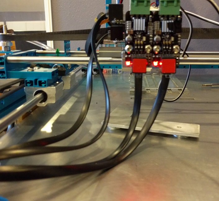
The receiver is connected to the MultiWii. Each channel on the receiver corresponds to a command on the controller. The transmitter sends out signals in the form of radio waves and the receiver converts those signals to electrical signals for the MultiWii to read. The connections on the receiver must be connected to the appropriate pins on the MultiWii in order to control it properly. Refer to this blogpost for MultiWii connections.

rc receiver

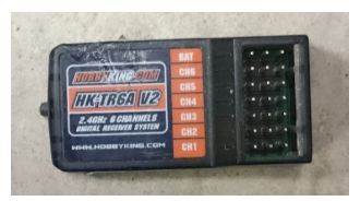
Fig 1.2 HK-T4A Receiver

Setting up the MultiWii:

To set up the MultiWii to be compatible with your quad, you need to download the MultiWii source code here. After getting the source code, go into the config.h file and select the appropriate configurations based on your project. To select an option, simply remove the comments(//).

For our project, we used:
#define QUADX
#define MINTHROTTLE 1150
#define MAXTHROTTLE 2000
#define I2C_SPEED 400000L
#define INTERNAL_I2C_PULLUPS
#define FREEIMUv035_BMP

Copy and paste this anywhere into the config.h file:
#define MAG_ORIENTATION(X, Y, Z) {magADC[ROLL] = -Y; magADC[PITCH] = X; magADC[YAW] = Z;}

Some things to mention are that the minthrottle should be kept as is. The quadcopter needs to be under a certain throttle to arm and if the minthrottle is set too high it won’t reach that arming point. Another thing is that for the board options, the MultiWii isn’t listed there, using FREEIMUv035_BMP would work as well.

MultiWii GUI:
The zip download for the source code included a GUI as well. The gui can be used to change the PID settings and calibrate the sensors. The GUI only monitors the sensors, you can’t control the device through it.

Arming and Disarming:
The most important commands for controlling the quadcopter is arming and disarming. Arming connects transmitter and receiver so that you can begin communication. Disarming disconnects the communication. If it flies out of control during testing, you can disarm to stop the motors from spinning. Typically, to arm you pull the throttle down and yaw to the right. To disarm you pull the throttle down and yaw to the left. This is convenient since you can arm and disarm with one joystick. The arming and disarming commands can be changed in the config.h file.

Works Cited:
https://www.youtube.com/watch?v=JyAyM1f_O3Q
https://www.arxterra.com/multiwii-esc-and-receiver-connections/
http://dl.btc.pl/kamami_wa/hk_27033_2.pdf


Single Event Upsets

By Chelsea Mediavilla (Electronic and Control)

This post discusses single event upsets (SEUs) and their effects. The choice in SEU monitor and implementation for the Spring 2016 SPARCCS project is explored.

Read more

Spring 2016 3D SMD: Verification Test — Cable Fatigue

By: Christine Vu (Missions, Systems, and Test)

Table of Contents

Cable Test

A test will be conducted to determine that the bending radius will have a minimum bend radius of 10x its cable diameter.

Requirements

Section 1 EE400D Assembly

The SMD pick and place machine shall pick up and place down all SMT components provided by any EE400D PCB up until the end of Spring 2016.

Section 1.1.4

All moving cables using RJ25 connectors shall have a minimum bend radius of 10x its diameter (Telecommunications Industry Association, 2001).

Applicable Tools

Equipment Type Name (Brand) Tolerance
Mitutoyo S/N 12519090 Caliper 0.001”
Measuring Tape Stanley 33-425 Powerlock 25-Foot by 1-Inch Measuring Tape +/- 3%

Background

According to previous studies (Weaver & Gutierrez, 2015), wire fatigue may occur during repetitive movement. The Makeblock X-Y Plotter Robot Kit moves in a confined area with multiple repeated values of X-coordinates and Y-coordinates. Therefore, our project may be subject to repetitive movement that may cause damage to the cables.

The Makeblock company overall lacks a large amount of datasheets for their parts, so it was difficult to determine the standards of their RJ25 cables and connectors. It was noted that it was a 6P6C connector, so we decided to reference Digi-Key’s supplier, Assman WSW Company, whose cable diameter size is 26 AWG. The datasheet is shown in Fig. 1.

DataSheet

Figure 1. Reference datasheet for AT-S-26-6/6/B-xx-R.

In addition, we referred to commercial telephone standards (Telecommunications Standard Association, 2001), which noted that wire bend radius should have a minimum of 10 times its cable diameter.

Due to the funding of this project, we will not imitate the rotary fatigue tests as done by Weaver & Gutierrez (2015). As a replacement of this test, we will measure the cable bend radii at each important area to assure compliance.


Diameter of entire cable = 6.8 ± 0.2 mm

Worst-case scenario = 6.6 mm


6.6 * 10 = 66 ± 0.2 mm = 2.59 ± 0.007 in.

Therefore, minimum bend radius shall be 2.59 ± 0.007 in.

Procedure

  1. Connect the wires attached to the X-Axis and Y-Axis.
  2. Control the Y-Axis and move to the farthest end of the plotter with respect to the PCB until the limiting switch is hit. Record the length of the cable.
  3. Control the Y-Axis to the other side of the limiting switch. Record the bend radius as shown as the photo below.The bend radius will be measured at the curved cable touching the aluminum surface.

CableTEst

Figure 2. Obtained from: https://en.wikipedia.org/wiki/Bend_radius#/media/File:Bendradius.svg

Results

Locations

The locations of each measured area is shown below.

IMG_20160503_191316 Bend Radius Measurements

Figure 3. Cable #’s of the RJ25 cables.


Cable # Y-Limiting Switch (in.) X-Limiting Switch (in.) Requirement Met? (Y/N)
1 N/A 3.843” Y
2 N/A 3.605” Y
4 4.587” N/A Y
5 4.655” N/A Y

Table 1. Cable Bend radii measurements.

Conclusion

Cables using RJ25 connectors can have a minimum bend radius of 2.59″ +/- 0.007″. The smallest bend radius was 3.605″, which is larger than the required amount. Therefore, this requirement is passed.

References

Assmann WSW Components. (2013). “Modular cable – Straight 6P6C 50u”, 26 AWG, Black, 5-50 feet”. Datasheet.

Telecommunications Industry Association. (2001). TIA/EIA-568-B.1: Commercial Building

Telecommunications Cabling Standard.

Weaver, J. , & Gutierrez, E. (2015). Comparing rotary bend wire fatigue test methods at different test speeds.Journal of Materials Engineering and Performance, 24(12), 4966-4974.


Spring 2016 3D SMD: Z-Axis Beam

By Henry Nguyen (Electronics and Control)

Table of Contents

Introduction

When running our accuracy tests, I found that the current beam on our Z-Axis would wobble. After carefully observing the wobbling, I found that this will be a major problem when we needed to assemble a PCB with surface mount components. The wobbling will cause our machine to be very inaccurate and may cause us to fail our machine.

Old Beam

Figure 1. Old Beam

Figure 1. Old Beam

Not only was our old beam wobbling because the holes where the 4mm rod went through were slightly larger than 4mm. This will cause the beam to lean forward due to the weight of our A-axis stepper motor. Now that the beam is being tilt forward, our Z-Axis stepper motor will sometime stall out because of the friction against the 4mm rod and the thread beam.

New Beam

Figure 2. Beam Measurements

Figure 2. New Beam Measurements

For our new beam, I decided to make it approximately 0.754 inches. This meant that our beam will be longer than our older beam. I believed by extending the length, we will be able to prevent the wobbling caused by the two rods. The middle hole shown in the figure above will be tapped for our thread screw. The two holes in the middle is to attached our A-Axis stepper motor bracket.

Figure 3. Z-Axis Beam Manufactured

Figure 3: Z-Axis Beam Manufactured.

I was able to get Z-Axis beam manufactured. I found that after installing this bracket, we were able to solve the problem of our Z-Axis stepper motor stalling due to the proper size hole that the rod is now able to go through perfectly.

Figure 4. Lubricant

Figure 4. Lubricant

It was also important to apply some CRC Heavy Duty Silicone lubricant onto the beam and the thread screw to allow smooth vertical movement of our new beam. The following link is a video of our new beam in action.

https://youtu.be/214bttIEprQ

Conclusion

It was very important to manufacture a new beam for our Z-Axis. Before we would have a lot of error caused by the Makeblock beam that came with our thread drive kit. The old beam would wobble a lot which is a major problem when we are trying to be as accurate as possible. Other times, the poorly manufactured beam would also cause our z-axis stepper motor to stall because it did not move up and down smoothly. By manufacturing this new beam we are able to increase our accuracy of our machine.


Spring 2016 AdBot System Block Diagram and Interface Matrix Definition

By Don T. (Mission, Systems, and Test)
Dang Le (Project Manager)

A system block diagram and interface matrix allow people to replicate the project. They show the components that are used and wire connections. AdBot’s interface matrix begins displaying all the Arduino Uno’s pins and names. Components are placed in columns. When an Arduino pin is not vacant anymore, the row turns white to indicate that the next component cannot place a jumper lead in the white box.

Figure 1 Interface Matrix Definition

Figure 1 Interface Matrix Definition

Figure 2 System Block Diagram

Figure 2 System Block Diagram

Resource Files

Link 1 AdBot Interface Matrix Definition Excel Sheet

The system block diagram is created using the full version of Shapes.

Link 2 System Block Diagram.shapesdoc

Spring 2016 A-TeChToP 3D Printed Case

By Mimy Ho (Manufacturing Engineer)

Introduction

We received the PCB back from the manufacturer in 2 weeks, soldering the PCB was done by the Manufacturing Division a week later. And we finally have the completed PCB, the next step is to design the 3D printed case for housing the PCB and battery.

Read more

Verification and Validation

By Jeremy Seiden (Mission, Systems, and Test)

I review the verification and validation table.

Read more

Mission, Systems, and Test: Trade-Off Studies

By Jeremy Seiden (Mission, Systems, and Test)

This study weighs the benefits and drawbacks of a discrete component based high voltage supply circuit, and an IC based high voltage supply circuit. The purpose of this study was to determine the most radiation hardened high voltage power supply method.

Read more

Mission, Systems, and Test: Experiments

By Jeremy Seiden (Mission, Systems, and Test)

I describe experiments we conducted to verify that the communication system was working properly. Specifically, we tested for and verified that our data was being properly packetized.

Read more

Spring 2016 SPARCCS Interface Definitions

By Jeremy Seiden (Mission, Systems, and Test)

I walk through the interface definitions for the project.

Read more