Spring 2016 SPARCCS Interface Definitions
By Jeremy Seiden (Mission, Systems, and Test)
I walk through the interface definitions for the project.
Introduction
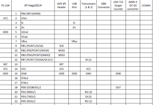
Below is the table containing the interface definitions for the 2016 SPARCCS instrument, as well as an explanation of the major subsystem interfaces. This table clearly distinguishes the connections between subsystem hardware present on the instrument. The columns represent the present subsystems. If any values share a row, that denotes a connection. In the ATmega32U4 column, the numbers on the left of the column represent the pins of the micro-controller chip. See the system block diagram for subsystem explanations.
| PC- 104 |
ATmega32U4 | AVR SPI Header | USB Port | Transceivers
(1 & 2) |
DB9 Connector | LND 712 Geiger Counter | A06N-5
DC-DC converter |
UcamII | |
| 1 | PE6 (INT.6/AIN0) | ||||||||
| VCC | 2 | UVcc | |||||||
| 3 | D- | D- | |||||||
| 4 | D+ | D+ | |||||||
| GND | 5 | UGnd | |||||||
| 6 | UCap | ||||||||
| 7 | VBus | VBus | |||||||
| 9 | PB1 (PCINT1/SCLK) | SCK | |||||||
| 10 | PB2 (PDI/PCINT2/MOSI) | MOSI | |||||||
| 11 | PB3 (PDO/PCINT3/MISO) | MISO | |||||||
| 12 | PB7 (PCINT7/OC0A/OC1C/) | DI (1) | |||||||
| RST | 13 | RST | |||||||
| VCC | 14 | VCC | VCC | VCC | |||||
| GND | 15 | GND | GND | GND | GND | GND | |||
| 16 | XTAL2 | ||||||||
| 17 | XTAL1 | ||||||||
| 18 | PD0 (OC0B/SCL/) | OUT | |||||||
| 20 | PD2 (RXD1/) | RO (2) | |||||||
| 21 | PD3 (TXD1/) | DI (2) | |||||||
| 22 | PD5 (XCK1/) | RO (1) | |||||||
| GND | 23 | GND | |||||||
| VCC | 24 | AVCC | |||||||
| 31 | PC6 (OC3A/) | RxC | |||||||
| 32 | PC7 (ICP3/CLK0/OC4A) | TxC | |||||||
| VCC | 34 | VCC | VCC | (+)IN | 5V | ||||
| GND | 35 | GND | (-)IN | GND | |||||
| VCC | 42 | AREF | |||||||
| GND | 43 | GND | HVRTN | ||||||
| VCC | 44 | AVCC | |||||||
| VCC | HVOUT | ||||||||
| Z (2) | TX- | ||||||||
| Y (2) | TX+ | ||||||||
| Y (1) | RTS- | ||||||||
| Z (1) | RTS+ | ||||||||
| B(2) | RX- | ||||||||
| A(2) | RX+ | ||||||||
| A(1) | CTS- | ||||||||
| B(1) | CTS+ | ||||||||
Interface Explanation
Supply voltage (Vcc) and ground (GND) connections can be found on components supplied from the PC-104 bus connection. SPI headers and USB port are connected to ATMega32U4 to allow interface with computer for bootloading. RS-422 Transceivers are connected to pins 20-22 of the ATMega32U4 and from there to the DB9 connector pinout for connection to computer. The UCamII occupies pins 31 and 32 for serial communication with the microcontroller, as well as a 5V and a ground connection. The Geiger tube output is connected to pin 18 to record events detected by the LND-712 Geiger Tube.