
Trade-Off Study: PCB Form Factor
By Eric Hanna (Design and Manufacturing)
I examine the pros and cons of Fall 2015’s PCB form factor versus the PC/104 standard.
By Eric Hanna (Design and Manufacturing)
I examine the pros and cons of Fall 2015’s PCB form factor versus the PC/104 standard.
By Eric Hanna (Design and Manufacturing)
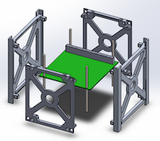
I discuss and walk through the hardware design of the overall cube satellite, including an exploded view of the payload and of the entire chassis.
By: Jerry Lui (Manufacturing Engineer)
This blog post is to address the redesign of the body to meet the following specific requirements:

To meet the requirement of printing under 6 hours, a major redesign of the body had to be done.
To cut down on the print time, prefabricated Tamiya wheels and tracks were used.
https://www.pololu.com/product/106
Parts of the body were removed and replaced with thin trusses to help with the stability of the body.
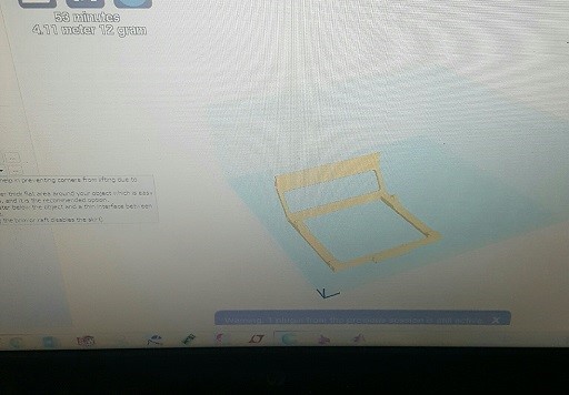
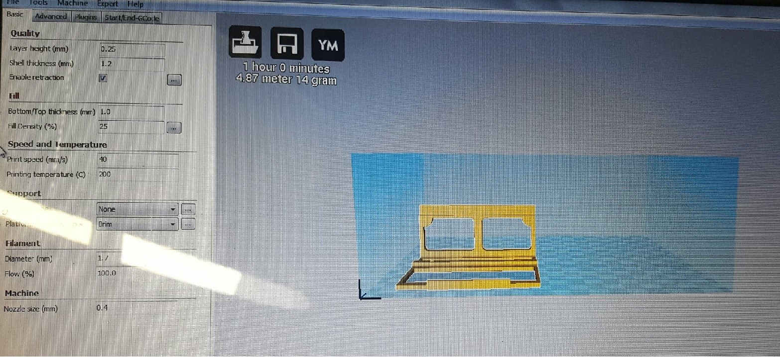
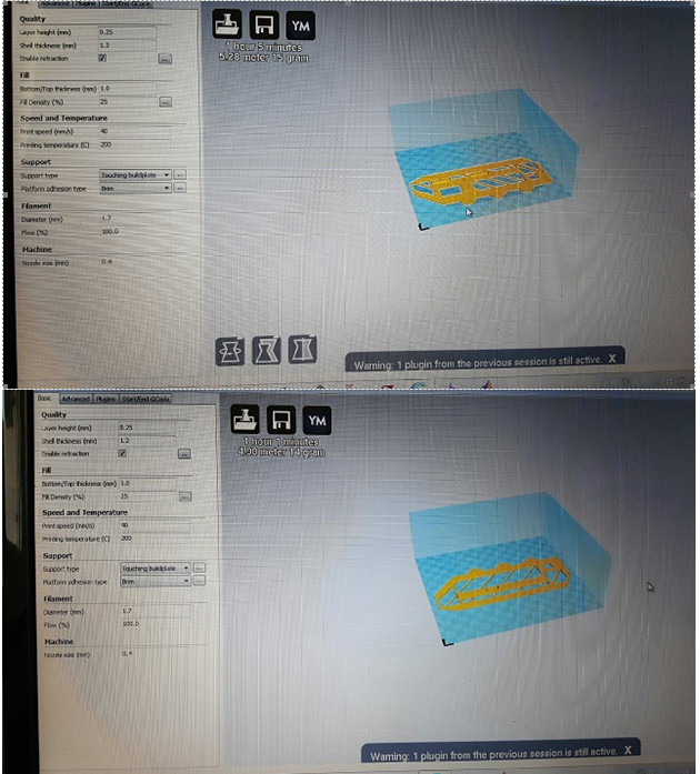
The printer supplied by Professor Hill was lacking around 0.5’’ to properly print the base and top in one go so I had to split the parts within Solidworks to 2 parts.
The height of the sensors and emitters was set to that it was exactly at 3 inches (+/- 0.01inches due to the PLA shrinking and expanding from the print)
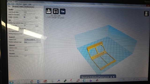
The body was printed with a 25% fill density, x1.2 wall thickness (typically x0.8 and x1.2 and always a factor of 0.4), and at a speed of 40mm/s. The print time was barely affected when changed to 0.8 so I opted to add slightly more rigidity to the body this way.
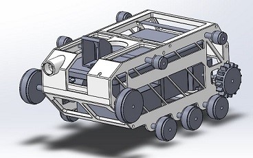
The body’s dimensions are essentially scaled down to the width of my Galaxy S4 phone (also held on by a ledge within the body) but it couldn’t have been an exact replica of the Goliath tank due to the print time requirement. There just wasn’t enough time to print all of the side panels and bolts while fitting the phone within the body of the rover.
The total print time came out to around 5hr 57minutes.
Conclusion
The redesign has met all but one requirement partially (scaled model). The model has the general shape of the tank but is lacking the panels and bolts.
Sources
https://www.pololu.com/product/106
By: Kevin Moran (Electronics and Control Engineer)
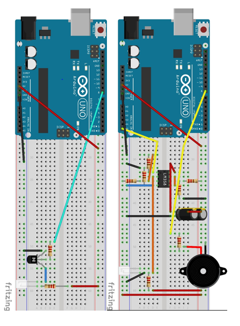
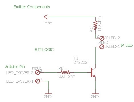
For Fall 2016’s 3DoT Goliath it was my job to design from scratch a printed circuit board that would allow our rover to emit and IR signal, and also process a receiving signal. This process started as a messy image on my notebook, and was later processed into a cleaner Fritzing diagram. The diagram for the circuit changed as the weeks progressed due to help from my division manager, and my attempts at making this circuit better each time.
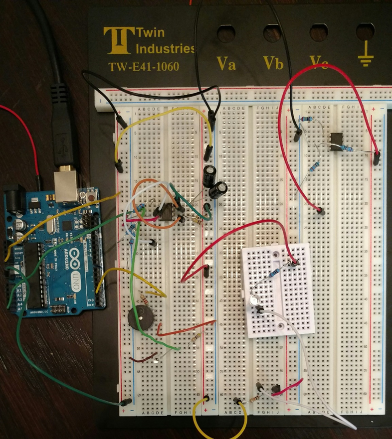
Testing:
Before processing to order the PCB a good amount of time went into testing the circuit below. I had to ensure that the capacitors used for removing the unwanted AC components from the power source were doing their job. I spent many hours testing various resistor sizes in order to ensure that the voltage thresholds were the correct ones with our 5V voltage supple. Once I felt sure of my decisions I moved to the next step, which was to design this circuit on Eagle CAD, in order to have the manufacturing engineer design the PCB board and order it. By this point, I already knew my emitter/ receiver combo worked, and that using the Schmitt trigger I was able to clean this analog signal and convert it to a single bit digital signal.
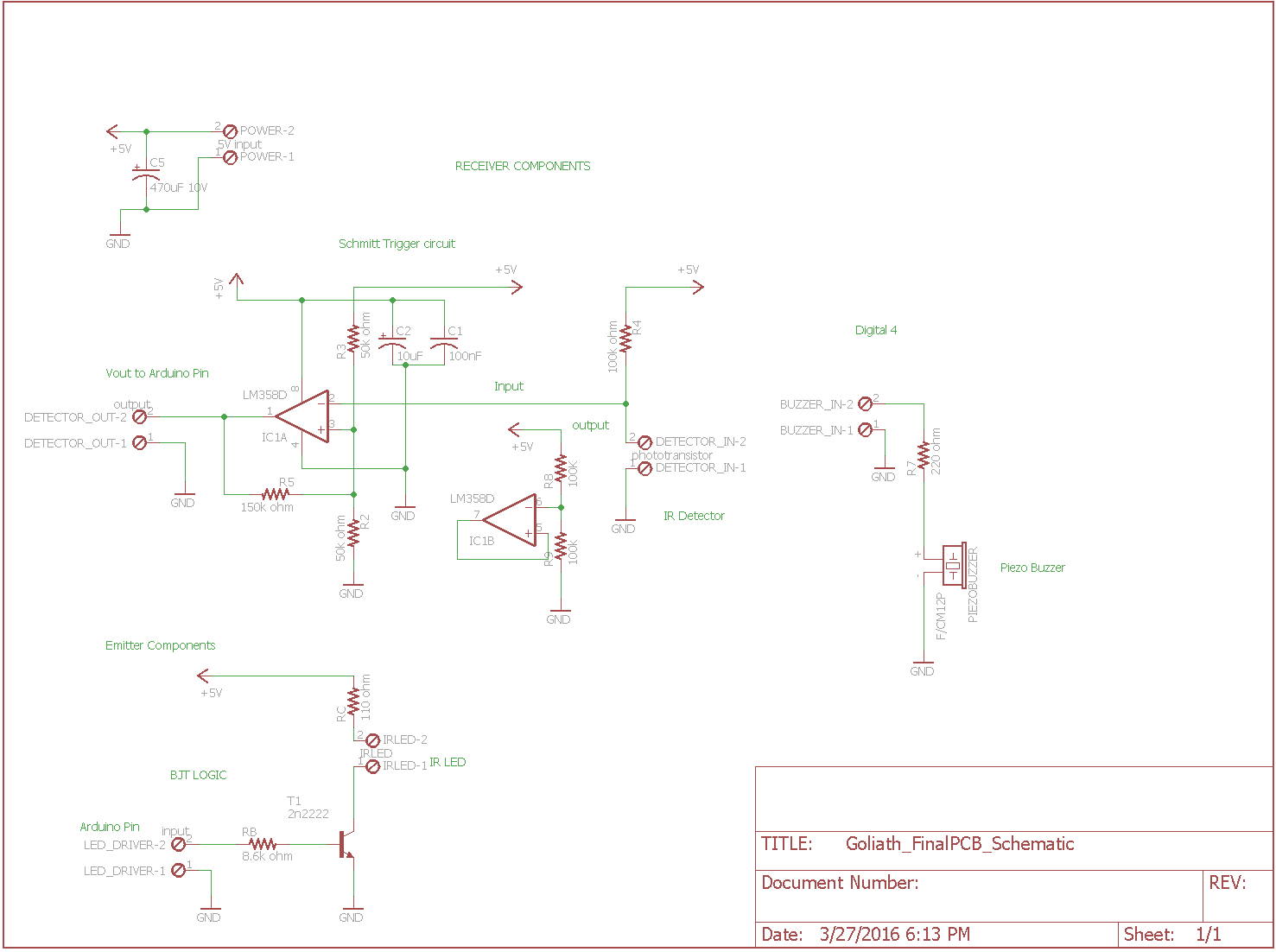
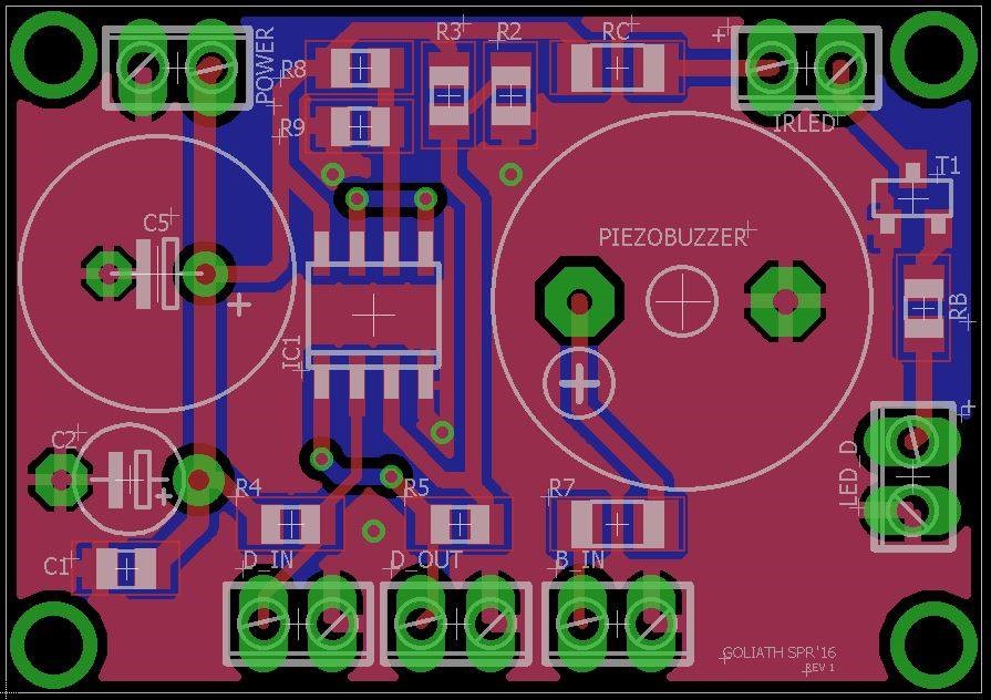
PCB Layout:
As can be seen below, all of the components are named, and have specific values. These values were obtained during the testing stage. All components of the circuit are properly grounded and given access to the power supply. The Piezo buzzer is hooked up to the 220 ohm speaker to regulate it output level. All other resistors were calculated to ensure the circuit works properly.
Note: If you are reading this, you will be provided with access to my Eagle Cad, and Fritzing diagram files, hopefully the next generation rover has an easier time.
Final Product: Put together by manufacturing engineer Jerry Lui
Sources:
Jeffrey Cool: Division Manager (Life savior)
http://hyperphysics.phy-astr.gsu.edu/hbase/electronic/schmitt.html
http://www.eng.utah.edu/~cs5789/handouts/piezo.pdf
By: Kevin Moran (Electronics and Control Engineer)
One of the things I mentioned in the previous posts, was that by using an IR emitter (LED), the range was very limited. Testing showed an average range of 3-6 inches. In order to have a reasonable range for the emitter, it was necessary to concentrate that diffused light. One idea was to use lenses to concentrate the light, the opposite idea of a flashlight which spreads out a smaller area light.
There were many lenses to choose from such as:
∙ Convex: Helps light rays to converge into a single smaller area
∙ Concave: Causes light rays to diverge or spread out (Opposite of what we needed).
∙ Spherical: Which are less focused and produce a wider light beam
∙ Compound: Which increases the focus while decreasing image distortion
The lenses that were decided to use along with Spiderbot’s E&C engineering were the convex lenses, since our emitter had a short range due to the diffusion of the light rays, it was a good idea to concentrate those rays into a small area.
Calculations:
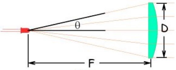
Looking online, we came across this formula that allowed us to calculate the distance that the IR LED would have to be from the lense in order to increase the range, to a distance that would work with our requirements
Using this formula and the values provided by the image below, we were able to calculate a suitable range.

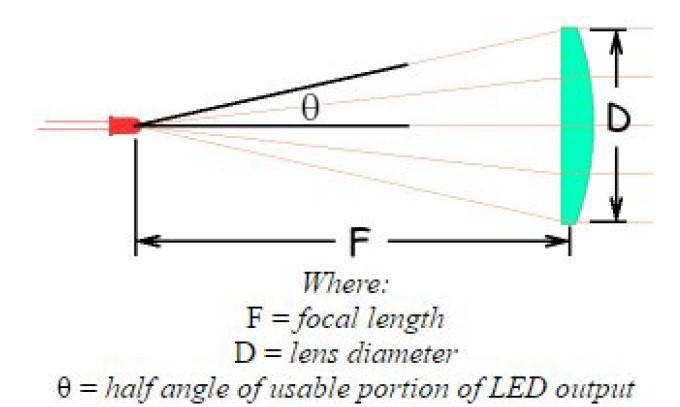
Using the diameter of the lenses I already had on me, along with the half angle provided by the datasheet of the IR LED. I came up with values to plug into this equation.
D = 11.3mm diameter (lens)
F = focal length
Θ = 40 (half angle intensity of the current emitter we are using)
D > 2*F*tan (Θ)
11.3mm > 2 * F * tan (40)
F < 6.73 mm
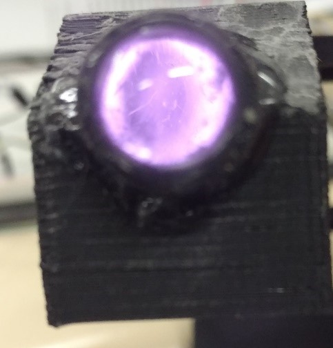
In conclusion in order to use the given lens diameter with our particular IR LED, the focal length (distance from LED to lens) has to be less than 6.73 mm. I asked the manufacturing engineer to provide with a small tube that can be used to further test these distances. As can be appreciated by the picture below, the light intensity has increased as long as our range to about 16 inches. We will continue to test to extend this range even more.
Sources:
http://alumnus.caltech.edu/~leif/infratag/lens_choice.html
http://physics.stackexchange.com/questions/146956/howtochoserightlensforconcentratingirsignal
http://micro.magnet.fsu.edu/optics/lightandcolor/lenses.html
Kent Hayes: Ordered the lenses for both teams

By: Kevin Moran (Electronics and Control Engineer)
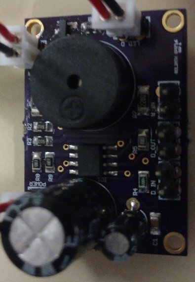
Once the PCB was assembled by the manufacturing engineer (Jerry Lui), it was to test it. If all the testing and assembling had been done correctly then the PCB should have worked with a problem. As testing began we quickly realized that the PCB was not sending any voltage to the IR emitter. With the help of Jeff Cool, Tae Le, and Jerry Lui, we realized that the problem was with the NPN transistor we had ordered.
The problem was with this 2n2222 transistor above. The RB was not being used as a base, but rather the collector (which should be connected to ground). After many attempts, we came to the conclusion that the SMD transistor had been placed wrong.
As can be seen by the arrow, once we compared the diagram of the transistor, with this picture, we realized that the resistor RB was going to the right connection of the transistor, when it should have been pointed to the left connector, and the right connector straight to ground. Thanks to the ingenuity and quick thinking of Jerry Lui, he was able to quickly fix this problem, by flipping the SMA transistor over. After that was fixed, we tested the IR emitter and we saw voltage going through it, and the receiver worked perfectly as well. Below is the final output of the PCB, converting an analog signal into a single bit digital signal! YAY!
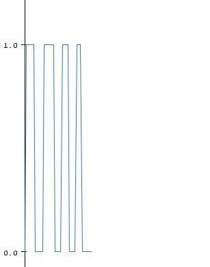
As can be seen, a perfect digital signal with either a 0 or 1 bit. On/off applications. Now we are ready to defeat the 3DoT Spider bot.
Sources:
http://www.mouser.com/ProductDetail/TTElectronics/2N2222ACSM/?qs=%2fha2pyFaduhY4tRQXhKL%2feLyX%252bM6m2ylmJNPJCp%2fVeaSnptWjDmpSA%3d%3d

By:
Lindsay Levanas (Design and Manufacturing)
Table of Contents
Although all previous posts regarding Spring 2016 Pathfinder’s chassis have focused on the rocker bogie suspension system design, the use of a Wild Thumper chassis was also considered and so it is worth documenting the iterative design loop that lead to the final product. This report will outline the decisions that had to be made and their impact on the design.
To start with, Spring 2016 Pathfinder’s level 1 terrain requirement is to traverse the CSULB campus at night.1 To this end, the rocker bogie suspension system was chosen and implemented as a level 2 requirement2 and a basic rocker bogie suspension system was modeled as an example.3
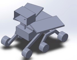
Figure 1. Basic Model of rocker bogie system
The idea modeled, the next step was to research into physical implementation.
As rocker bogie suspension systems require particular dimensions to function properly, it was decided that purchasing a working model would be best. Therefore, rocker bogie chassis were researched and only one was found to be purchasable: the Bogie Runt Rover from ServoCity.4
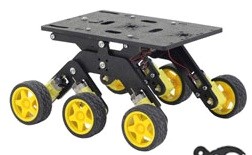
Figure 2. Bogie Runt Rover
Having found a rocker bogie suspension system, the next step was to conduct a trade-off study between that and a Wild Thumper chassis. Note that Spring 2016’s Pathfinder is meant to improve upon the design that came before it and that this is where the Wild Thumper chassis is coming from.5 Below illustrated the initial trade-off study between the two chassis.4,8,9,10

Figure 3. Chassis Trade-Off Study
After listing the different aspects of the two chassis systems, the important factors need to be clarified. To start with, the width of the tilt system (at least 10.48in)6 is dictated by the use of a Google Tango Tablet, and so needs to be considered. Also, the weight of the load that Spring 2016’s Pathfinder will carry is at least 2.45lbs from the tilt system alone as shown below.
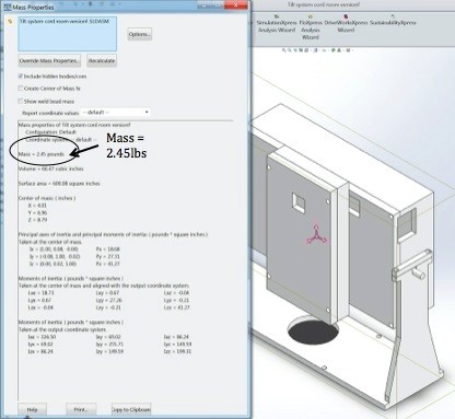
Figure 4. Tilt System Mass Properties
On top of all this, the chassis needs to be able to hold the pan system, electronics, electronic protection box, batteries and solar panels. Although at this point in the design process these additional parts had yet to be finalized, the concern of going over the weigh capacity (and surface area) of the Runt Rover was still relevant and so was taken into consideration when choosing a chassis. Also considered was the terrain the chassis could handle under load.
Given that the Runt Rover base was smaller then the tilt system width, and that it could only carry up to 4lbs on smooth terrain, the Wild Thumper was chosen to be Pathfinder’s chassis at this time.
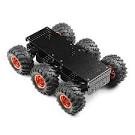
Figure 5. Wild Thumper Chassis
Not long after the Wild Thumper was chosen as the chassis, a new resource was made available to Spring 2016’s Pathfinder team. This resource was aluminum cutting and milling. This meant that the Runt Rover previously viewed as too small could be modeled in Solidworks, simplified, doubled in size, and cut out of aluminum. To see how this would compare to the Wild Thumper, the proposed rocker bogie system was modeled in Solidworks so that size and weight could be properly estimated.7
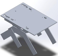
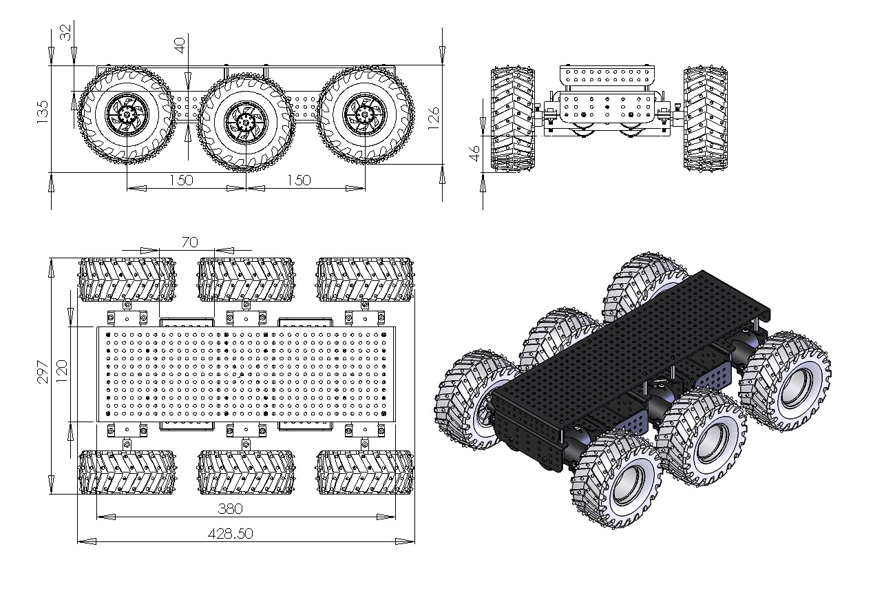
Figure 6. Rocker Bogie System
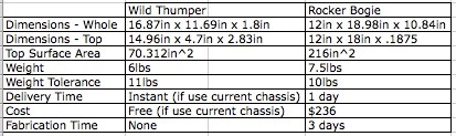
The above picture compares the specs of both chassis
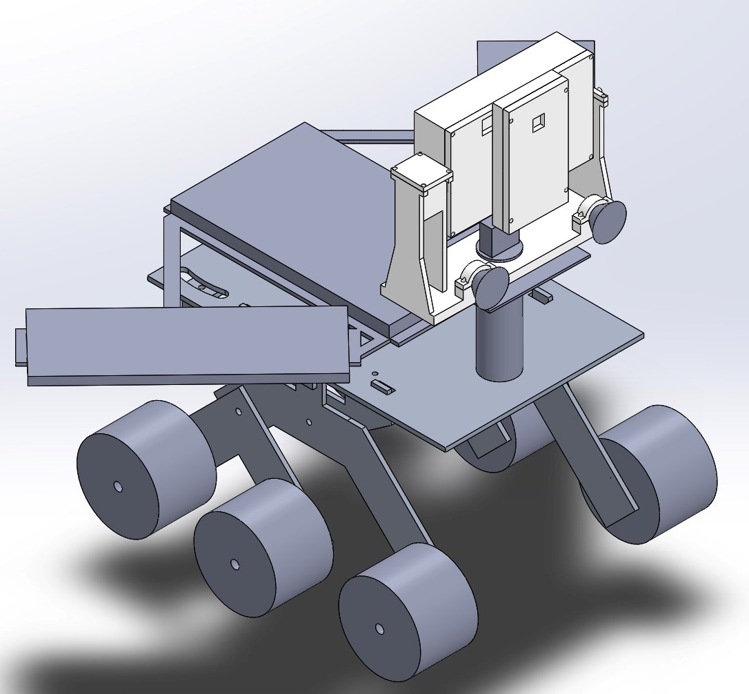
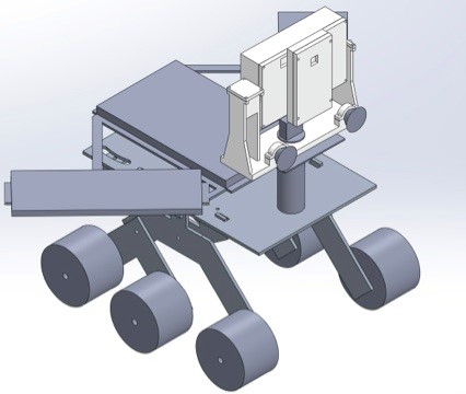
As the Rocker Bogie design allowed for 145.688 more square inches of top surface area and 9.04 more inches of obstacle avoidance clearance for a loss of only 1lb of weight tolerance and 1.5lbs of unloaded weight, the Rocker Bogie design was chosen as Spring 2016’s final Pathfinder chassis. A sample model of the chassis with its future load is shown below.
Source Materials:

By:
Lindsay Levanas (Design and Manufacturing)
Table of Contents
This report will serve to document how the Spring 2016 Pathfinder’s PCB layout was designed in EAGLE7.5.0 Light. Reference to the PCB schematic outlined in Spring 2016 Pathfinder: PCB System Schematic1 will be mentioned, as well as safety precautions from outside sources. Note that all components will be surface mounted, and all jumper pins will be through hole.
Although Eagle is designed to carry over the component’s wiring from the schematic to the board’s layout (then called airwires), the connections between pins can sometimes be hard to see. For example, in the illustration below, where does the top airwire (the thin yellow line) go? Does it connect straight to the bottom pin of JP4? Or does it connect to one of JP4’s other pins too?
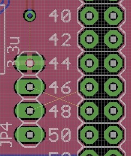
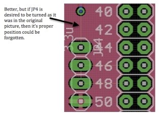
Therefore, in addition to rotating the part (which can be hard to keep track of), the original schematic can also be referenced to verify that the proper connections are being made.
Using the above part as an example, the equivalent part in the schematic can then be used as a reference.
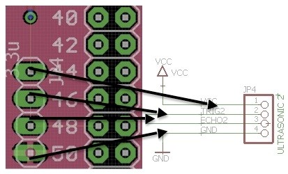
Since pins 2 and 3 are accounted for with single connections and ground does not use an airwire, the top connection can then only be to pin 1.
Note that this process can be used for any component where the connection seems unclear. Now that a general idea has been obtained for the PCB’s wiring, safely measures can be looked into next.
To ensure that the PCB is able to function properly, the amount of current through the circuit needs to be considered. If the traces are too small for the amount of current they need to carry, then they run the danger of burning out.2 According to the Power Test3 the max amount of current Spring 2016 Pathfinder’s PCB will be carrying is 140mA.
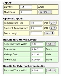
Using a trace width calculator (shows above) for PCBs,4 the minimum desired trace width can be found.
Note that as Spring 2016 Pathfinder’s PCB traces will be on external layers, the width of the trace needs to be no smaller then .393mils.
To check the trace width in Eagle, right click on any trace and select Properties. In the pop up box, check the width number against the grid units. This will tell you what units the width is being measured in as Eagle bases all numbers on the grid units.
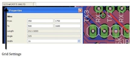
As is illustrated above, the traces are set to have a width of 16mils. As this is larger then the trace width calculations, the trace sizes do not have to be changed.
For optimal functionality of the buck converter, the TPS56428 chip needs to be considered. This means that the circuit layout included in the chip’s datasheet5 must be followed, or the PCB may not work. Below is the proper setup outlined in the datasheet followed by the corresponding PCB layout.
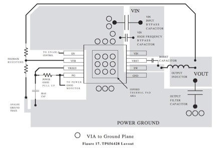
In conclusion, Spring 2016 Pathfinder’s PCB will follow the corresponding PCB schematic, current safety precautions and proper chip layout. After fabrication, the next step will be to solder all of the parts onto the board.

By:
Juan Acosta (Electronics & Control – MCU Subsystem and Firmware)
Tuong Vu (Electronics & Control – Sensors, Actuators, and Power)
Table of Contents
Project Pathfinder required the use of an Arduino Mega, VNH5019 motor shield, PCA9685 Servo PWM Controller, two HC-SR04 ultrasonic sensors, two servos, six DC motors, HC-06 Bluetooth Module, LED Headlights, and Buck regulator. Each device we chose to use will help us accomplish our mission by meeting set level 1 and 2 requirements. For more information on testing and implementation of these devices, visit the previous blog post Spring 2016 Pathfinder: Subsystem Design
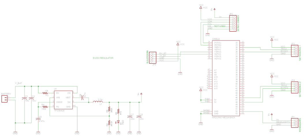
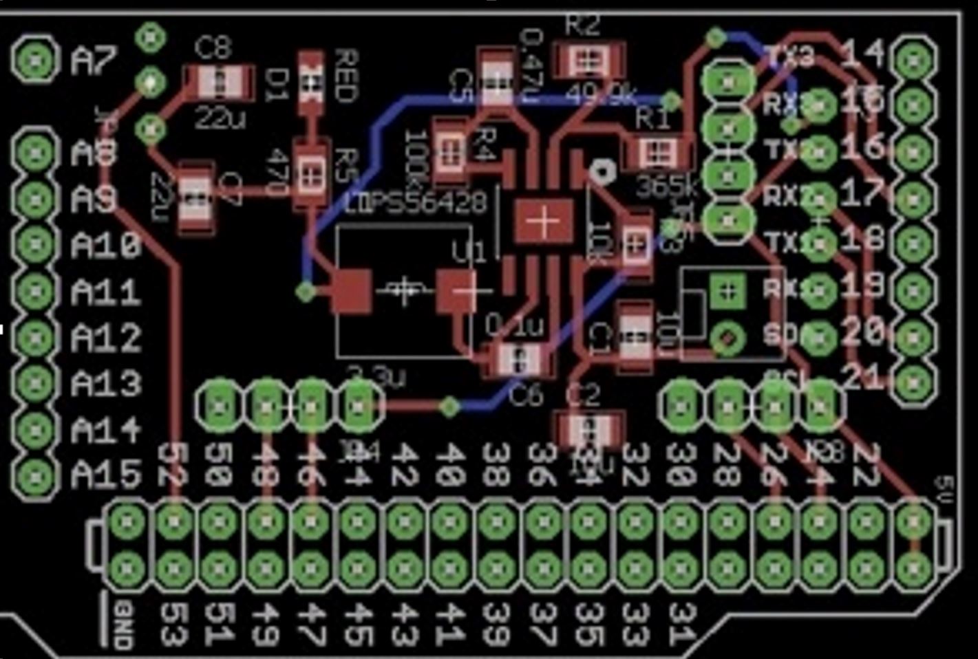
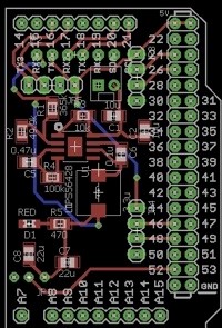
As discussed in our Subsystem Design, we decided that it would be best if we created a custom PCB that would allow us to take advantage of the leftover pins of the Arduino Mega. So in our custom PCB design, we aimed for a PCB that would interface with the Arduino Mega as a shield. In our PCB schematic we have allotted different headers for the two ultrasonic sensors needed for obstacle collision prevention, headers for the PCA9685 Servo Controller that we chose to safely power and drive our pan and tilt servos, headers for the HC-06 Bluetooth module needed for wireless communication, headers for the L.E.D. headlights needed for lighting, and TPS56428 buck regulator needed to step down voltage to 6 volts to protect the servo driver from 7.4V.
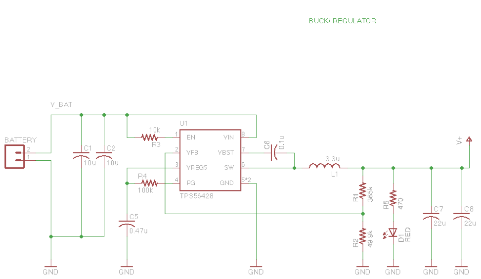
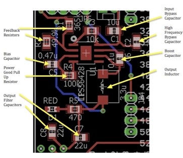
The figure above focuses on the buck regulator. We chose this buck regulator because it was found most efficient during testing. We used the data sheet provided by Texas Instruments in order to find the necessary resistance values for Resistors R1 and R2 which control the duty cycle needed for an output of 6 volts. For resistor R1 we got 355 K and 49.9 Kfor resistor R2. Aside from the necessary resistors and capacitors outlined in the guide sheet for the TPS56428, we also added capacitors C1 and C2 for noise cancellation and a red L.E.D. in series with resistor R5 in order to show when the circuit is on.
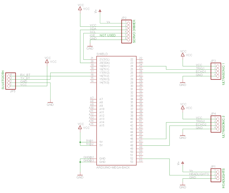
The figure above focuses on the through hole headers we will be using to directly plug in our two ultrasonic sensors, headlight L.E.D.s, Bluetooth module, and servo driver.
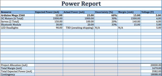
During testing it was found that the max current draw for the PCA9685 servo driver was about 140 mA. The max current draw for the HC-06 bluetooth module was 25 mA. The max current draw for the L.E.D. headlights was 90 mA. The max current draw for the motors was 1 A. Lastly, the max current draw from the HC- SR04 ultrasonic sensors was 20 mA. For more info reference the Power Report below.
Keeping all of the voltage and current ratings of each device in mind will help during the routing of the custom PCB. Because different components need different current ratings to operate normally, the size of the traces in our PCB should reflect the amount of current that will go through these traces.
– EagleCAD download:
http://www.cadsoftusa.com/download-eagle/
– TPS56428 buck regulator:
http://www.ti.com/product/TPS56428
– Spring 2016 Pathfinder: Subsystem Design
http://arxterra.com/spring-2016-pathfinder-subsystem-design/

By:
Juan Acosta (E&C – MCU Subsystem & Firmware)
Table of Contents
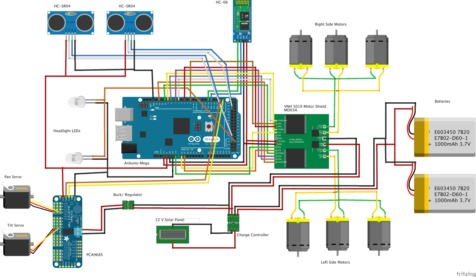
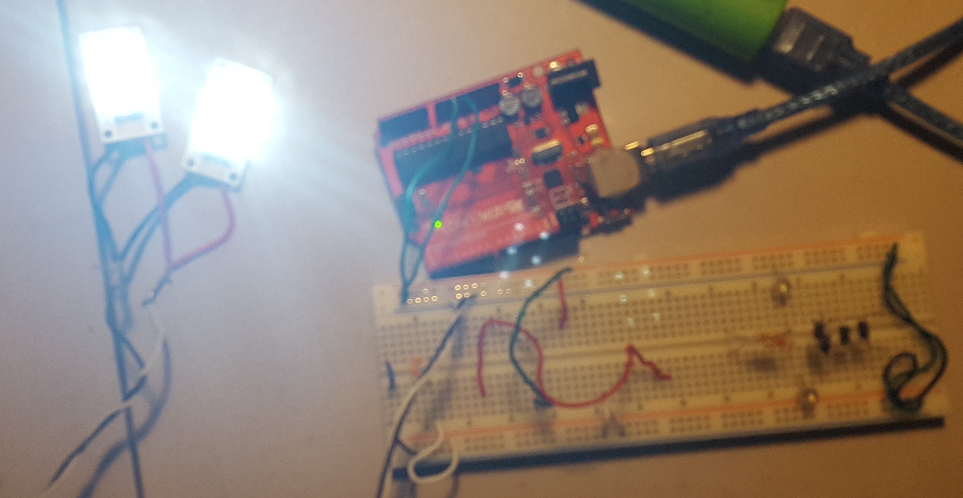
The fritzing schematic above depicts the circuit we used for testing the Wild Thumper Chassis’ motors, batteries, ultrasonic sensors, headlight L.E.D.s, servo driver along with servos, the motor shield along with the six motors driving the rover, and the Bluetooth module.
Earlier testing showed us that the Arduino Mega that we are using would leave us with plenty of unused pins, so we contemplated switching micro- controllers to the Arduino Uno. But after more experimentation we found the need for a servo driver to drive our pan and tilt system. We also found the need of digital pins to control the headlight L.E.D.s, communication pins for the Bluetooth module, and control pins for the ultrasonic sensors. Because of these needs, we determined that it would be best if we kept using the Arduino Mega.
As you can see from the fritzing diagram, the VHN5019 motor shield utilizes a little more than half of the Mega’s pins in order to drive the motors. So we decided to make another custom PCB shield that would serve to drive the HC-06 Bluetooth Module, the HCSR-04 ultrasonic sensors, the L.E.D. headlights, and the PCA9685 servo driver.
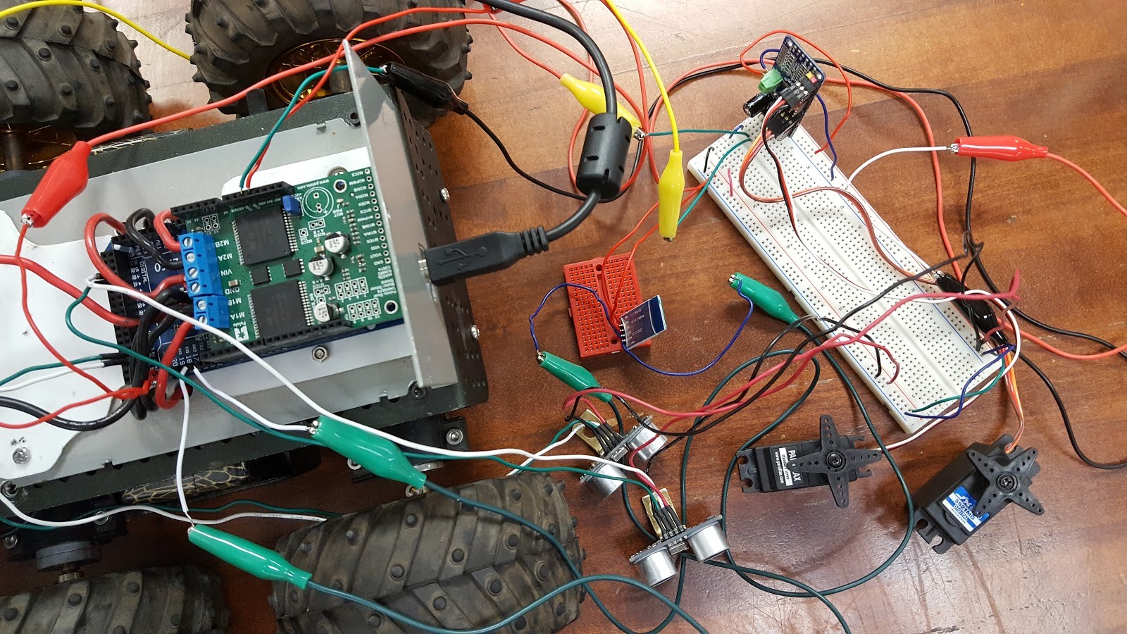
The photo above depicts the circuit we used for testing the ultrasonic sensors, the servos, the Bluetooth module, the motor shield, and the servo driver.
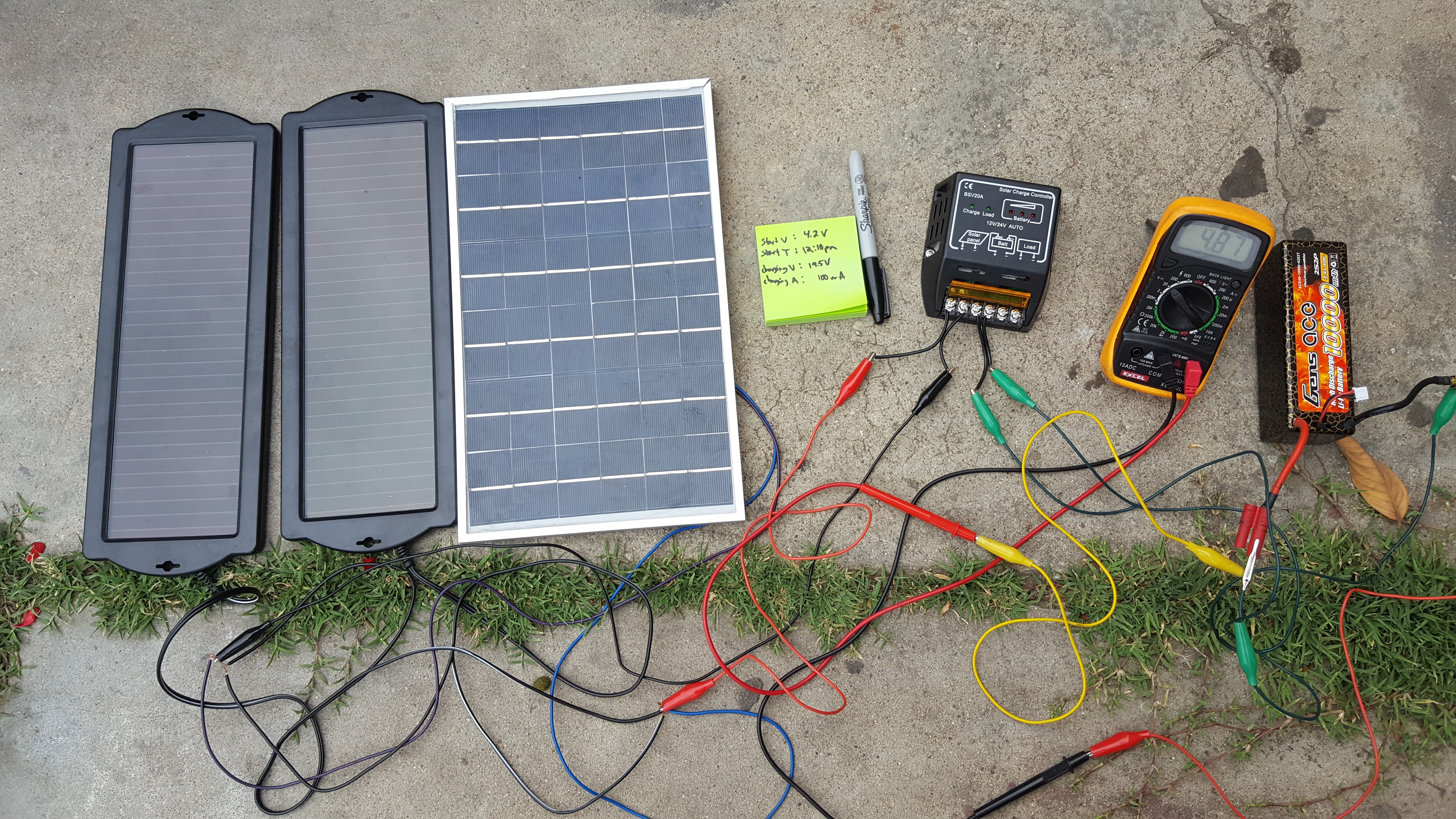
For our charge control circuit, we chose to use the Black Menba 20A 12V/24V Solar Charge/ Panel Battery Controller. We chose this solar charge controller because our initial charge controller design proved to be inoperable after thorough testing.
For initial design, reference previous blog post Spring 2016 Pathfinder Charging Control Circuit
Check more on blog post Spring 2016 Pathfinder Solar Panels Implementation
For our L.E.D. headlights, we chose to use the 6 Piranha 5V Led Light Panel Board. For this decision, we had only two factors: price and brightness. These L.E.D.s proved to be very bright meeting our expectations and making sure we met one of our requirements of aiding the pathfinder with lighting.
For more information see blog post Spring 2016 Pathfinder: LED Headlights
– 6 Piranha 5V Led Light Panel Board White Night Lights Lamp Super Bright:
http://www.ebay.com/itm/181941929073?_trksid=p2057872.m2749.l2649&ssPageName=STRK%3AMEBIDX%3AIT
– Black Menba 20A 12V/24V Solar Charge/ Panel Battery Controller:
– SMAKN® 16 Channel PWM/Servo Driver IIC interface-PCA9685 for arduino or Raspberry pi shield module servo shield:
– Spring 2016 Pathfinder: LED Headlights
http://arxterra.com/spring-2016-pathfinder-led-headlights/
– Spring 2016 Pathfinder Charging Control Circuit
http://arxterra.com/spring-2016-pathfinder-charging-control-circuit/