Spring 2016 3DOT Goliath, 3D Printing Requirement: “Round One”

By: Rickeisha Brown (Manufacturing Engineer)

As a level one requirement, the customer requests to refrain from exceeding a total of 6 hours 3D printing time and not to exceed two hours per printed component. The customer has a project total budget of which ultimately limits the amount of spending power per division. Printing Cost estimates which is of total budget.

Maker’s Society is the organization handling our 3D prints. Their printers can print multiple parts at a time, they’re conveniently located on the campus of CSULB, and are reasonably priced to $5 per hour. Visit their website for more details regarding Maker’s Society and the services they offer: http://lbmakersociety.org/about-us/.

I submitted my design to Carlos Vergara1, the AESB representative, and informed him of my 6 hour printing requirement. He uploaded the parts to a program which examines each component and estimates total printing time down, to the minute.

1

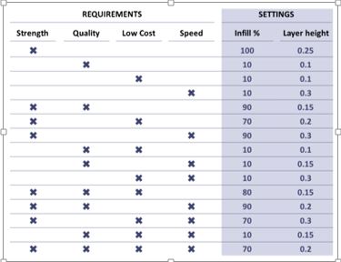
Figure 1: The table above shows the trade-offs between strength, quality, low cost, speed vs. layer height. 2

2


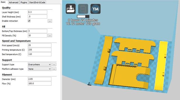
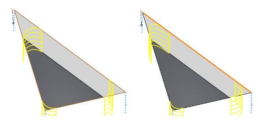
Figure 2: Maker’s Society printing time estimates for the original body with 0.3 mm layer height: 8 hours and 24 minutes.

Figure 2 shows the results for total printing time of Goliath components with 0.3 mm layer height, with 0.2 mm being an ideal layer height based on Figure 1.

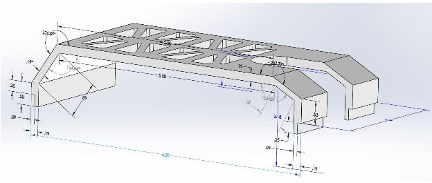
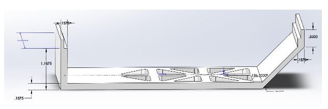
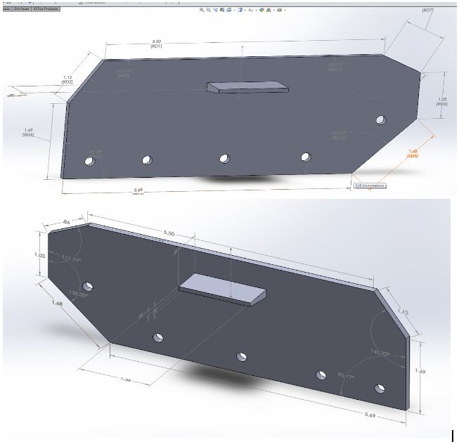
This does not meet level one requirement, so we must revert to Plan B: reducing the amount of components which make up our body from 6 to 3 components, sides (2), and cellphone and periscope compartment (1).

Here are the results:

3


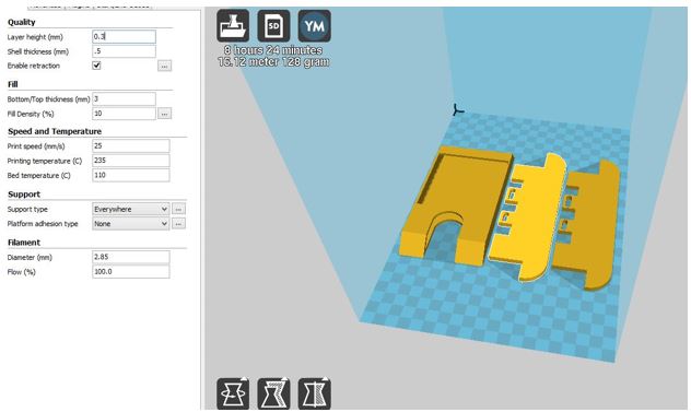
To my surprise, the printing time did not decrease!

I requested that Carlos increase the layer height to 0.4 mm which will decrease printing time and help our team meet the 6 hour printing time requirement. Here are the results:

4

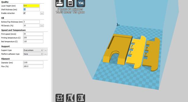
For 3 components, the total time still exceeds 6 hours. Therefore, I will go back to the drawing board readjust components thickness.

References:

1-Carlos Vergara, AESB Representative for Maker’s Society, E-mail: carloslbvergara@gmail.com

2- “What Is the Influence of Infill %, Layer Height and Infill Pattern on My 3D Prints?” 3D Matter. N.p., 10 Mar. 2015. Web. 23 Mar. 2016.


Spring 2016 3DOT Goliath, PM Tool ” Smartsheet”

By: Ayman Aljohani (Project Manager)

The major role of PM is to successfully manage the team to meet customer requirements thus have a functioning product at the final demo. That couldn’t be done without keeping track of project’s critical path to know what is done as per schedule and what is delayed. Knowing that would provide the PM with multiple options and solutions to steer the project toward a successful result.

One important tool of project management I used is Smartsheet:

Smartsheet1

Smartsheet is 30 days free, after that there are 3 different plans to choose from. The basic plan which I used costs $10 monthly for annual plan, or $13 for a monthly plan:

Smartsheet 4

Once you sign up, you will have an access to variety of templates to choose or a blank sheet:

Smartsheet 5

This is a video that explains creating new project sheet:

Creating New Project Sheet


Smartsheet 6

With Smartsheet you can easily generate Waterfall diagram “Gantt Chart”, here is a video on how to generate it :

Gantt Chart View


What makes Smartsheet powerful project tool is that it allows collaborators to work on it as well, depending on the access given to them by the owner of the sheet (Project Manager), they can be editors, viewers, or admin. Editors will have limited access on the sheet to edit tasks, i.e completion percentage. However, columns or rows that the owner doesn’t wish editors to have access to should be locked :

Smartsheet 7

To lock a column or row :

1-Highlight row or column

2-Right click

3-Lock Row, or Column


Once a task is assigned to someone, they can be notified via email. The following video shows how to set alerts and reminders:

Alerts And Reminders


One cool feature of Smartsheet is iPhone App. Project manager can easily manage their projects using Smartsheet app.

Smartsheet apps

This video explains how to use the app to upload photo on Smartsheet:

how to upload photo to Smartsheet using the app


If a team member wants some clarification on assignment, they can start a discussion with PM on Smartsheet discussion column:

Smartsheet 9

Smartsheet 8


The “attach” option allow collaborators to add copy of their work to keep track of project documents.

Smartsheet 10


Once the sheet is ready to be shared, “Sharing” at the bottom of the sheet provides owner the option to share the document with collaborators:

Smartsheet 11


Burn Down is an important chart PM should keep an eye on thus Smartsheet allows PM to generate it easily. To do that, PM should add ” Planned Assignments” column, ” Planned Start Date”, ” Planed End Date” . Then highlight these columns and generate report.

Also, you can export the project sheet to Excel or MS project and generate the Burn Down from there.

Smartsheet 12

Sources:

Smartsheet website


Spring 2016 A-TeChToP Manufacturing Design of EDA Watch Bands

Marena William (Manufacturing Engineer)

In the past few weeks the housing for the seizure watch was designed and 3D printed as a prototype. The focus currently is on how the electrodes for detecting electrodermal activity will be placed on the wrist and how the electrodes’ wires will be running on the straps of the watch.

Read more

Spring 2016 3 DOT Goliath Arxterra Control Panel Test

By:  Tae Min Lee (Mission, Systems, and Testing Engineer)

As we get closer to the final product we started implementing the Arxterra Control Panel that will be used for the demo.  The Arxterra Control Panel will be used to control the Goliath and provide a live video feed from an android phone with a periscope.


Setup for Arxterra Application on Android/apple Device:

Going on your android/apple device go to the Arxterra application and click on community (see figure 1).

1


Now tap the connect button (see figure 2) and wait for the next screen to show up (see figure 3).

Now assign the robot’s name using an Arxterra application on the android/apple device.  For this example, I used TaeML7 as my pilot’s name and robot name as TaeML.


2           3


Arxterra Control Panel Setup:

Logging onto Arxterra using your computer type in your pilot’s name you assigned on your Arxterra application on your android/apple device.  For the password you can type in any password you wish for the login on Arxterra Control Panel (figure 4).

4

Once your login onto to the Arxterra control panel you should be able to see the robot name on the map (ex. TaeML).  Now click on the green man to enter the cockpit of the robot (Figure 5).

5


Now were in the cockpit of the Goliath where it displays the controls, speed, and battery levels of the Goliath (Figure 6).


7


Arxterra Control Panel Test:

After testing the Arxterra Control Panel we were able to control the Goliath by pressing a key on the keyboard (W = forward, A = left, S = backward, D = right).  In addition, the android device was able to provide a live video feed with the periscope as seen on figure 6.


Sources:

  1. https://www.arxterra.com/bluetooth-interface-to-arxterra-application-in-progress/
  2. https://www.youtube.com/channel/UCJXZGMpv8GqxkOi6W02GzoQ

Spring 2016 3 DOT Goliath Arxterra Firmware Motor Control Modification Test

By:  Tae Min Lee (Mission, Systems, and Testing Engineer)

In order to use the Arxterra control panel we need to first implement the Arxterra firmware for the Goliath.  After testing the Arxterra firmware we encountered a problem with the motor control.  Since, the Arxterra firmware is implemented to using TB6612FNG motor control we had to make a few changes to the firmware to use the Arduino motor shield.

The following changes were made to implement the basic movements of the Goliath:

firts pic Tae


The run_AMS function is responsible for setting the direction and brakes on a motor.  In this case we treated IN1 of controlling the direction on the motor and IN2 to controlling the brakes.

The following table will indicate the movement of the Goliath:

secon Tae

Setting a HIGH value for IN1 will make the motor move forward.  While setting a LOW value for IN1 makes the motor go backward.  In addition, the brakes are activated when we set IN2 variable to HIGH on the motors and setting a INT2 to LOW we will disable the brakes.

To make a right turn on the Goliath we made the motor on the left side to go forward while the motor on the right go backward.  This provides a faster method of turning the Goliath to the right.  A similar action can be performed for the left turn by having the motor on the right go backward and the motor on the left go forward.

third pic Tae


Sources:

  1. https://www.arduino.cc/en/Main/ArduinoMotorShieldR3
  2. https://www.arduino.cc/en/Tutorial/DueMotorShieldDC


Spring 2016 A-TeChToP Analog Electrodermal Signal Processing

By: Robin Yancey (Systems Engineer)

A highly accurate electrodermal activity signal, within a precise frequency range and voltage level, is obtained by developing a simple circuit for analog pre-processing [1]. This circuitry is used to limit the current to the electrodes to a safe amount, measure the resistance between the electrodes, and amplify the signal for input to the ADC of the BTLC1000 chip.

Read more

Spring 2016 3 DOT Goliath IR sensor Code

By: Tae Lee (Systems Engineer)

IR Sensor Code

To implement the laser tag game we have to show an indication of when the Goliath gets hit by the enemy’s IR LED. This will be shown through the three LEDs we will be using to indicate the number of hits.

The following code shown below will be used to implement the three hit indicator:

IR code1


IR code 2

The general idea of how this code operates will be shown by the block diagram below:


IR code 3

The code will start by checking if a signal is received at the detector. If the detector detects the IR emitter it will light up one of the LEDs and increases the count. The count will be used to indicate the number of hits received by the enemy. As we get hit the count will increase to power each LED until it reaches 3 hits. The if statement will be used to check if the Goliath receives 3 hits, which will disable the Goliath. Otherwise, it will do nothing and it will repeat the program through a loop.

Spring 2016 A-TeChToP Temperature Sensor

Mimy Ho (Manufacturing Engineer)

Introduction

The digital temperature sensor DS18B20 was selected based on the level 1 and level 2 requirements of the project: weight, accuracy, and safety. The sensor is waterproof and therefore safe for a child who sweats during play. This blog post focuses on the initial testing and implementation of the sensor.

Read more

Spring 2016 3 DOT Goliath body dimensions

By: Jerry Lui, Rickeisha Brown (Manufacturing Engineers):

Given the requirement of having the phone housed within the body of the rover the body must accommodate for the dimensions of the particular phone being used. In this case, a Samsung Galaxy S4 is being used as the camera for the rover and has the dimensions of 5.38”x2.75”x0.31” (1). Also, to be able to see through the horizontally placed camera a periscope will be used with a dimension of 13/16’’x13/16’’x1-1/16’’.

manufacturing 1


The top lid has a length of 5.5’’ which gives a clearance/play of 0.12’’. The top portion also has a slot to accommodate the periscope and is set to 1’’ (free space of 3/32’’ per side) to allow for movement and alignment of the scope.


Next, portions of the body was removed to reduce the weight of the rover with the sharp corners of the sections filleted with a conic rho profile. The conic rho profile (default solidworks value at 0.5) adds a smoother transition from the adjacent faces yet is able to keep close to the original shape of the cutout instead of having an extremely rounded corner.

manufacturing 2

Also, since we want to be able to access the phone quickly the top should be removable and to accomplish that without having seating issues both the top and the bottom has ledges that sit within each other. Tolerances will be given and set to 0.01574”or 0.4mm (2). The periscope gives a90°shift in the view so that we can see directly forward of the rover.

manufacturing 4


manufacturing 5

The side designs are simply easier to construct, since they are solely based on the top and bottom component configuration. The sides are also going to support the various housing of components such as: motors, batteries, 3dot board, and pcb.


As you can see by the figures above, the side components support the wheel axeling, from the motor to the wheel itself. The diameter of each hole measures 0.1” which is the diameter of our screws and our our rod components. This is the exact measure of the diameter of the rods and screws that are used for our rover.


The inner side features include ledges for the cellphone placement. The ledge is centered about the top measurement 5.50” and begins 0.53” from the top of the rover, consider the thickness of the cell phone, the periscope will sit just perfect outside of the body, with enough area to for viewfinder.


Sources

  1. http://www.gsmarena.com/samsung_i9505_galaxy_s4-5371.php
  2. http://makezine.com/2013/12/11/top-ten-tips-designing-models-for-3d-printing/


Spring 2016 A-TeChToP ECG Demonstration

By: Stephen Cortez (Electronics Engineer)

For the electrocardiogram (ECG) demonstration, the group was required to generate a real-time ECG signal from a subject and transmit the signal to over to the Arxterra website either on a phone application or a computer through Bluetooth. The following is the process taken in order to develop the ECG circuit and develop communication both from the Bluetooth module to the phone and from the phone to the Arxterra app.

Read more