Fall 2016 Prosthetic Hand – Final Documentation
Project Manager – Kimberly Younger
Mission, Systems, and Test Engineer – Mia Lai
Electronics and Control Engineer – Younis Al-Kharusi
Design and Manufacturing Engineer – Wilson Mach
Table of Contents
Project Overview
Project Objective/Mission Profile
By Project Manager – Kimberly Younger
Mission Profile:
- As defined by the customer, the project mission of the prosthetic system shall allow a soldier requiring a prosthetic arm to eat a McDonald’s Quarter Pounder with Cheese meal. The prosthetic system will be designed to support the large community of wounded soldiers needing a prosthetic arm. While a fixture may be used to hold the meal, the other arm may not be used to feed the hungry soldier. In order to accomplish this goal, the prosthetic system will be manufactured as two separate entities, including a prosthetic arm and a prosthetic hand. The two entities will be able to attach and function as a single unit.
Project Objective:
- In order to achieve the mission profile, generalized program objectives needed to be qualified. The program objective is to use a part of the body that is not the hand to effectively control a prosthetic hand. The control would include wrist rotation ability and finger grasping ability. In conjunction with a Prosthetic Arm, the system would be able to feed someone a fast food meal without an allotted amount of time, being 20 minutes.
General Design
By Project Manager – Kimberly Younger
- Humanoid
- Five Fingers
- Palm Facing Flexion
- Gloved to Match Aesthetic of Arm
- Motors
- 5 DC Motors (Flexion)
- 1 Servo (Thumb Rotation)
- 1 Servo (Wrist Rotation)
- Force Sensitive Resistors
- On each finger, excluding thumb
- Capacitive Touch Panel
- Open Hand Mode
- Wrist Clockwise Mode
- Wrist Counterclockwise Mode
- Burger Mode
- Drink Mode
- Fries Mode
Figure 1: Printed and Assembled Hand (Back)
Figure 2: Printed and Assembled Hand (Front)
Project Features
By Project Manager – Kimberly Younger
Codependent Features
- PCB Housing in the Forearm
- Provided by Prosthetic Arm Group
- Kill Switch
- Emergency Power Off System provided by Prosthetic Arm Group
- Shared Power
- EMG Controlled Arm
- Interface Control Document
- Independent Control Systems
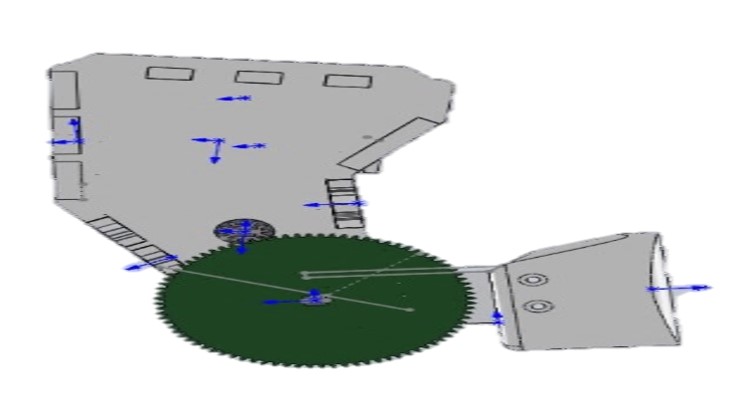
Figure 3: Solidworks View of Arm Prototype
Independent Features
- Wrist Turning
- Many independent Prosthetic Hands currently on the market do not offer any mechanism for pronation or supination of the wrist
- 7 Actuators
- 5 DC motors for flexion, 1 Servo for thumb rotation, 1 Servo for wrist supination
- Capacitive Panel from Foot
- A capacitive panel controlled by the foot/feet will control the motors
- Bluetooth
- Communication from foot to hand will happen wirelessly using an Xbee module
Figure 4: Solidworks View of Hand Prototype
Requirements
Level 1 Requirements
L1-1 –The mass of the Prosthetic Hand shall be less than 1.3 kg
Extending from the elbow down to the hand, length of 35 cm, the stepper Motor can provide torque of 10.634 Nm as dictated by the Arm group. The stepper motor will provide torque to lift the forearm and the hand in combination of food. The torque needed to lift the forearm will equal to the weight of the forearm, which is less than 2.34 kg, multiplying the distance from the elbow to center mass of the arm, which is located at the middle point of the forearm. Similarly, the torque needed to lift the hand and food will equal to weight of hand and food combination multiplying to the distance from elbow to the midpoint of the palm. The system shall be capable of picking up a maximum of 0.69 kg of food. From this requirement, the mass allocation for the Prosthetic Hand is 1.3 kg
Calculation:
T Elbow= T Forearm + THand and food = 10.634 Nm (1)
T Forearm = (2.34kg*9.81N) (0.35/2) = 4.01 Nm (2)
T Hand and Food = (Mass Hand + 0.69kg)* 9.81N*0.35m (3)
Solving system of 3 equations above we have the mass allocation for the hand is 1.3 kg
L1-2 – The Prosthetic Hand shall have same size as average human hand size.
L1-3– The total cost of the project should not exceed 200 USD.
R1-4 – The project shall be completed on or before the end of the CSULB Fall 2016 Semester, which is 12/22/2016, as defined by the CSULB Academic Calendar
L1-5 – The Prosthetic Hand shall be capable of gripping a medium drink/malt, Quarter Pounder with Cheese, and a bundle of French fries (1-10 fries per bundle).
L1-6 – The Prosthetic System will not be controlled the other hand.
L1-7 – The Prosthetic Arm and Prosthetic Hand shall coordinate to have a matching outer size appearance.
L1-8 – The Prosthetic system shall fit in the class room cabinet.
L1-9 – Prosthetic Hand shall have customized PCB.
Level 2 Requirements
L2.1 – In order to retain food from slipping out of the hand, the hand shall be capable of providing a minimal grip force of 13.4 N.
L2.2.1 – In order to provide a grip force of 13.4 N, the Motors shall be capable of providing a minimal torque of 0.143 Nm.
L2.2 – The Prosthetic Hand shall include wrist rotation of 90 degrees up and 90 degrees down
L2.2.1 – The stepper motor at the wrist of the hand shall be capable of providing a minimal torque of 0.01 Nm to rotate the hand.
L2.3 – To avoid deformation of the meal items, the hand system shall include force sensors feedback system
L2.4 – The Prosthetic Hand shall maintain operation below noise level of 60 dB as average measured noise level at a McDonald Restaurant [1]
L2.5 –Average time for a person to eat a meal is about 20 minutes [2]. Therefore, Prosthetic Hand shall share power source with prosthetic Arm to ensure operation of the Prosthetic system for least 20 minutes.
The following blog post details how the above numbers were calculated:
http://arxterra.com/fall-2016-prosthetic-hand-force-and-torque-calculations/
System Block Diagram
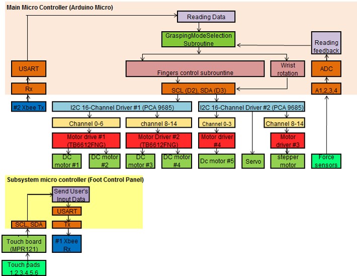
Figure 5: System Design Block Diagram
By Missions, System, and Test Engineer – Mia Lai
System block diagram consists of a main system MCU, which is located in hand/fore arm unit, and a subsystem MCU, which is located at foot control panel. The Foot control panel will receive user’s input signal from a capacitive touch panel. The subsystem MCU will package and transmit input data to the main system MCU wirelessly via two Xbee modules. The Main System MCU reading date and call responding subroutine the turn on and off the actuators that control movement of the finger and rotation of the wrist. In addition, four force sensors, which is located at the fingertips of the hand, will detect pressure applier on the fingers and send feedback signal to the main MCU. The MCU will process information and send a signal to turn off the actuators when the reading pressure reaches the threshold values.
Interface Control Document
By Missions, System, and Test Engineer – Mia Lai
The Interface Control Document laid out how the prosthetic hand and prosthetic arm would interact.
It can be found here:
Subsystem Design
Interface Matrices
Figure 6: Main System Interface Matrix
By Missions, System, and Test Engineer – Mia Lai
The interface matrix shows pinouts of the system. The highlighted cells indicates the pin has been used and the while cell show the pin is available for uses. In Main-system, The Arduino Micro has 20 digital input/output pins. Pin 0 and pin 1 are connected to output and input of the Xbee module. These two pins are reserved for receiving and transmitting data between the Xbee Module and the MCU of the system. Two I2Cs are used for communication between the microcontroller and the actuators, including five Dc motors, a Thumb servo, and a Wrist servo. These actuators are controlled through these I2Cs, which require only two Arduino serial pins (SCL, SDA). Four Force sensors can be connected directly to Arduino analog pins: A1, A2, A3, and A4.
Figure 7: Sub-System Interface Matrix
By Missions, System, and Test Engineer – Mia Lai
Similarly, Arduino Micro in sub-system MCU communicates with the capacitive touch sensor via serial pins (SCL and SDA). The via RX and TX pins are reserved for receiving and transmitting data to the Xbee module.
Figure 8: I2C 16-Channel PWM Driver Interface Matrices
As shown in the figures below, each I2C controls can four motors (or two motor and a stepper motor) via 2 dual motor dual motor drivers. Pin A0 to A5 are reserved for power and ground connection.
Mission Command and Control
Figure 9: Mission Command and Control Diagram
By Missions, System, and Test Engineer – Mia Lai
The challenge of our design is the Hand must pick up three different meal items: a burger, cup of soft drink, French fry, which vary in size, shape, and weight. The grip force must much be strong enough to hold the object but cannot be too strong to crush the object. We came up with the design that allows the user to control the movement of the Hand with 6 input buttons: Burger Mode, Drink Mode, Fry Mode, Open Hand Mode, Turn Wrist Clockwise Mode, Turn Wrist Counter Clockwise Mode. The Micro Arduino of the subsystem MCU, located at the foot control panel, will read input information from the user and send the data to the main system MCU, which is located in the Hand. Based on the user’s input information, the main system MCU will determine which grasping mode should be executed, then call modules (or subroutines) that corresponds to user’s input information. Four Force Sensors at the fingertips of the Hand detects pressure applied on the food items and send feedback to the Main system Arduino Micro, which processes sensor data feedback and calls the StopGrasping() Module to turn off all actual of the System.
System Flow Chart
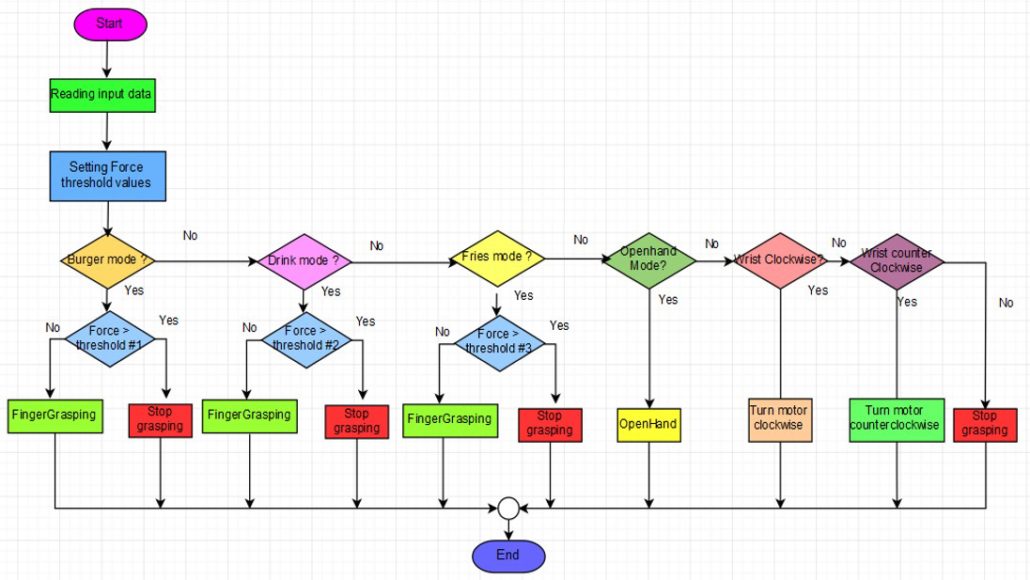
Figure 10: System Flow Chart
By Missions, System, and Test Engineer – Mia Lai
The flowchart presents the algorithm to solve our design problem. Based on user’s mode selection, the system will send different signals to turn motors clockwise or counter clockwise to bend (flex) or extent the fingers. When the user presses any food-grasping mode, the system will compare the force value from the sensor to predefined threshold values for Burger, Drink, and Fry modes. The system will turn off the actuators, when force applied the food items is greater than the threshold value. In case the sensors fail to detect the pressure, our system design allows the user to stop the Hand from crushing the food by simply depressing the input button.
Experiments and Prototypes
By Electronics and Control Engineer – Younis Al-Kharusi
The following blog posts depict the evolution of the electronic designs of the hand.
First, a prototype was constructed to showcase singular finger flexion.
http://arxterra.com/fall-2016-prosthetic-hand-finger-flexion-prototype/
Next, a control was experimented with flex sensors and bluetooth.
http://arxterra.com/fall-2016-prosthetic-hand-pdr-rapid-prototype/
Then, more broad goals were met by showcasing grasping mechanisms using button control.
http://arxterra.com/fall-2016-prosthetic-hand-motor-and-control-experiments/
Finally, the end product was a result of the following.
http://arxterra.com/fall-2016-prosthetic-hand-final-code/
PCB
Fritzing Diagram
Figure 11: Fritzing Diagram
By Electronics and Control Engineer – Younis Al-Kharusi
Breadboard Implementation
Figure 12: Breadboard Implementation
By Electronics and Control Engineer – Younis Al-Kharusi
Schematic
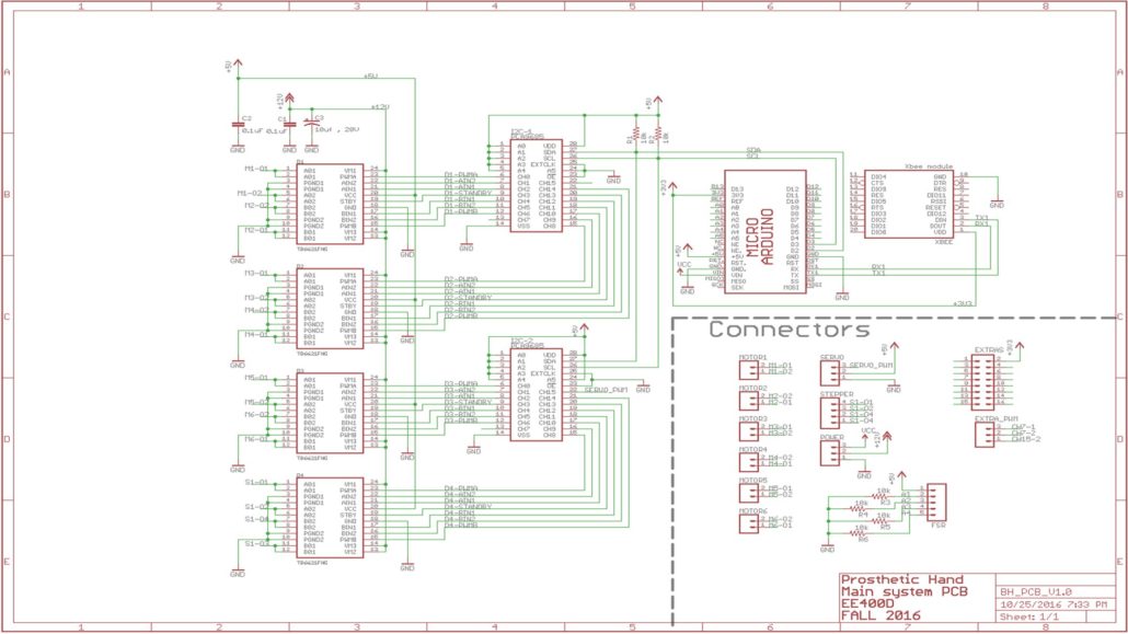
Figure 13: PCB Schematic
By Electronics and Control Engineer – Younis Al-Kharusi
The PCB Schematic is described in this blog post:
http://arxterra.com/fall-2016-prosthetic-hand-pcb-schematic/
Layout
By Design and Manufacturing Engineer – Wilson Mach
The evolution of the PCB layout is best represented using the following blog post:
http://arxterra.com/fall-2016-prosthetic-hand-evolution-of-pcb-layout/
Hardware Design
By Design and Manufacturing Engineer – Wilson Mach
The mechanical design of the prosthetic hand was a long and iterative process.
The learning process and initial designs can be found at this blog post:
http://arxterra.com/fall-2016-prosthetic-hand-mid-semester-manufacturing-update/
The process of 3D printing and modifying can be found at this blog post:
http://arxterra.com/fall-2016-prosthetic-hand-3d-printing-and-modifications/
The solid works designs can be found at this blog post:
http://arxterra.com/fall-2016-prosthetic-hand-evolution-of-solidworks-modeling/
The evolution of the PCB can be found at this blog post:
http://arxterra.com/fall-2016-prosthetic-hand-evolution-of-pcb-layout/
And the capacitive touch panel design can be found at this blog post:
http://arxterra.com/fall-2016-prosthetic-hand-capacitive-touch-panel-design/
Project Completion
Verification and Validation
Verification Test were conducted throughout the life cycle of the project to ensure success. A copy of this report is available at the following link.
https://drive.google.com/file/d/0B6I4NO4PN77SQl9xR0dPQnFnRzQ/view?usp=sharing
Burn Down
Figure 14: Burn Down Chart
By Project Manager – Kimberly Younger
This burn down chart demonstrates the timeline of the project in terms of percentages. The blue line represents the scheduled and planned progress while the red line depicts actual progress. Throughout the life cycle of the project, there were delays that had to be made up for at the very end.
Resources
[1] Project Video:
[2] Preliminary Design Document
http://arxterra.com/fall-2016-prosthetic-hand-preliminary-design-document/
[3] Preliminary Project Plan
http://arxterra.com/fall-2016-prosthetic-hand-preliminary-project-plan/
[4] Preliminary Design Review
http://arxterra.com/fall-2016-prosthetic-hand-preliminary-design-review/
[5] Critical Design Review
http://arxterra.com/fall-2016-prosthetic-hand-critical-design-review/
[6] Eagle CAD files
https://drive.google.com/drive/folders/0B6I4NO4PN77SbGs0UjlZTjkyVGs?usp=sharing


