Fall 2016 Prosthetic Hand: Motor and Control Experiments
Electronics and Control Engineer – Younis Al-Kharusi
Table of Contents
DC Motor Experiment (ESCAP vs. UXCELL)
At first, we choose to go with ESCAP 16 DC motors that are used on the actual tact hand design from instructables as our calculations yield that each finger will need a about 0.143Nm of torque to hold a full drink and the motors are spiced at 0.143Nm as well. After testing the motors, each motor draw about 1A of current when stalling and about 400mA on average. When only have 3.5A to operate all DC motors and the wrist actuators. If all motors stall at the same time, the current drawn by DC motors will be around 5A. The other thing about ESCAP 16 DC motors is that it is rated at 540rpm which too fast for the finger movement. The video shows current test when two motors are connected and movement speed. We ended up using another UXCELL 12V 10RPM DC motor that draws about 100mA at full load and has a toque of 0.19Nm.
Here is a link to this experiment video:
Wrist Motor Experiment (Stepper vs. Servo)
Initially, we were going to use NEMA 17 stepper motor to control wrist rotation. Initial torque calculations yielded a minimum torque of about 0.018Nm. The stepper motor chosen had a torque of 0.26Nm. When testing the stepper motor the motor was not able to move the hand easily nor hold it in place. The stepper was drawing about 0.6A of current when trying to hold itself in place and about 0.4A when moving. After that, we recalculated the minimum torque to be 0.6Nm when the hand holds a full drink. Then decided to go with Hittec HS-645MG Servo so we have more control over position. The servo can handle up to 0.98Nm at 6V. In addition, the stepper motor weighs about 220g vs 55g for the servo.
When tested, the servo was able to handle 1.86 pound smoothly drawing about 0.9A of current.
Here is the cup weight video:
https://1drv.ms/i/s!AtATn2tNizopgRPutJe8LMvWaM5n
And here is the servo test video:
Control Experiment (Buttons vs. Panel)
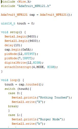
After testing the Arduino joystick shield we thought that the joystick it too small to be controlled by two feet, So we decided to make a capacitive touch panel that has 6 spaced out touch pads. The touch panel is controlled using Adafruit MPR121 12-key capacitive touch sensor breakout board. The breakout board has 12 capacitive touch pins and it detects if anything conductive touches pins. When you connect wires to the pin the breakout board has to be powered off then on to readjust itself. Our touch pads were made of aluminum tape connected by wires to the breakout board. The breakout board communicates with Arduino through I2C and the Adafruit_MPR121.h library makes it easier to detect when one of the pins is touched by using touched() function. The function outputs 1 for touched sensors and 0 for untouched sensors. The outputs is in the form of two bytes.
Here is the link for the touch panel code:
https://drive.google.com/open?id=0BzJlMPCB0tFPTVlOM2NiRmJ5STA
References
[1] Touch Sensor Breakout Tutorial
[2] Escap Gear Motor Encoder
http://rogerparks.com/instructional/escap-16-gear-motor-encoder/
[3] GearBest Motor
http://www.gearbest.com/development-boards/pp_70998.html?wid=21


