Fall Biped 2016- Foot Design
By: Hector Martinez (Manufacturing Engineer)
Approved by: Ijya Karki (Project Manager)
Table of Contents
Introduction
Requirement
“Shall be able to walk a minimum speed of 0.32 mm/sec.”
After CDR, we discovered that our foot design was inhibiting the weight shifting that the Theo Jansen Biped (TJB) toy provides. After careful inspection, it was noted that a simple design oversight resulted in a failed CDR demonstration.
Foot Testing and Design Methods
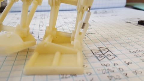
Fig. 1 – TJB toy foot with weight shifted on left foot.
The image above shows the TJB toy with its weight shifted to the left foot. Notice the link on the right with the metal cylinder, this ankle link is what causes the TJB to lean to the left and shift its weight. In this position, the right foot is able to take a step. Also notice that the ankle link is not perpendicular to the foot, instead, the angle between the ankle link and foot is necessary to allow the biped to lean. Without this clearance the biped would not be able to shift its weight and take a step.
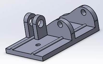
Fig. 2 – CDR foot with changed orientation of mounting bracket for ankle link.
While designing our biped, I ran into an issue which I believed to have a simple solution. The links for our TJB inspired legs are being laser cut, all the links are oriented the same direction except the ankle link. I decided to change the orientation of the ankle link to match the rest of the links because this would make laser cutting easier. I failed to realize that by changing the orientation of the ankle link I also changed the orientation of the pivot angle.
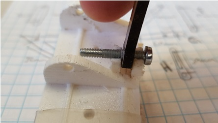
Fig. 3 – Close-up of 3D printed foot for CDR.
Notice in the picture above that the pivot angle of the ankle link is now parallel to the foot and not perpendicular as shown in figure 1. This change caused the mounting bracket to collide with the ankle link, restricting the angle necessary to make the biped lean. There was not enough time to 3D print a new foot with the proper mounting bracket orientation, thus, a quick solution was to break the top of the mounting brackets and super glue a machine screw to hold the ankle link in place. This was by no means an ideal solution and in order to make the foot work properly and redesign is necessary.
Conclusion
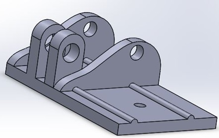
Fig. 4 – Redesigned foot which will be used on final product.
In order to make the foot work properly the orientation of the mounting bracket for the ankle link had to be changed to match that of the TJB toy. Additionally, the ankle link will have to be 3D printed to accommodate the orientation of the mounting bracket as well as the orientation of the rest of the leg links, which are offset by 90 degrees.
References
[1] http://www.rubberbug.com/walking.htm
Resources
[1] Solidworks