IR Sensors
Introduction
A key feature of MarioBot is being able to interact with other players. This interaction takes place in the form of being able to “throw” green shell items at other players. The green shell item disables the other player’s motors for 2 seconds if it makes contact with them. In order to achieve the player interaction, MarioBot decided to go with an IR Emitter and Receiver combination.
Research
No previous 3DoT team has attempted to use IR Emitters to communicate before, therefore there was no legacy research to build off of.
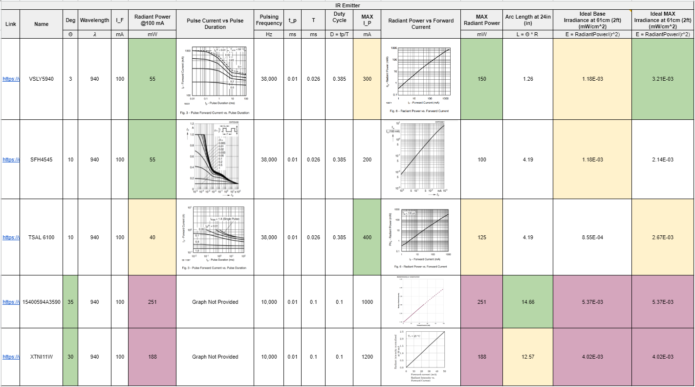
Figure 1 IR Emitter Research Table
Figure 1 shows the IR Research Table for various types of IR Emitters. The important factors to consider when picking an IR Emitter is the half-angle, forward current, radiant power, arch length, and irradiance.
The half-angle measurement determines the spread of the IR beam. For the purposes of MarioBot, we need to target the player in front of MarioBot and not to the side, therefore we need a very shallow angle.
The forward current is directly related to the radiant power. The higher the radiant power, the better the irradiance at a certain distance. Therefore we want to pick an IR emitter that has a shallow half-angle, with high radiant power.
The forward current can also be increased by changing the duty cycle of the IR emitter. We can choose to pulse the IR emitter at 38kHz (which is conveniently the same frequency as our commercial TV remotes), and that lets us increase our forward current more as seen by the chart in Figure 1.
Therefore we want to pick an IR emitter with a shallow half-angle, with a high forward current at the 38kHz duty cycle. Looking at the chart in Figure 1, the best all-around choice is the TSAL6100 with a half-angle measurement of 10 degrees, 400mA forward current at 38kHZ duty cycle, and max radiant power of 125mW.
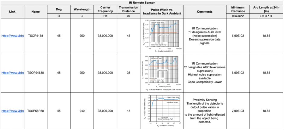
Figure 2 IR Receiver Research
After selecting an IR Emitter we have to select an IR Receiver. Figure 2 shows the IR Receiver research table. The IR receivers shown are all IR Digital Remote Receivers that filter any IR that is not pulsed at 38kHz. This eliminates any ambient IR from the environment. These digital remote receivers are active low and output a low signal once an IR pulse at 38kHz is detected.
For our purposes, we decided to test with the TSSP58P38 with the TSAL6100, since they were one of the cheapest options and had all-around similar specifications.
Testing
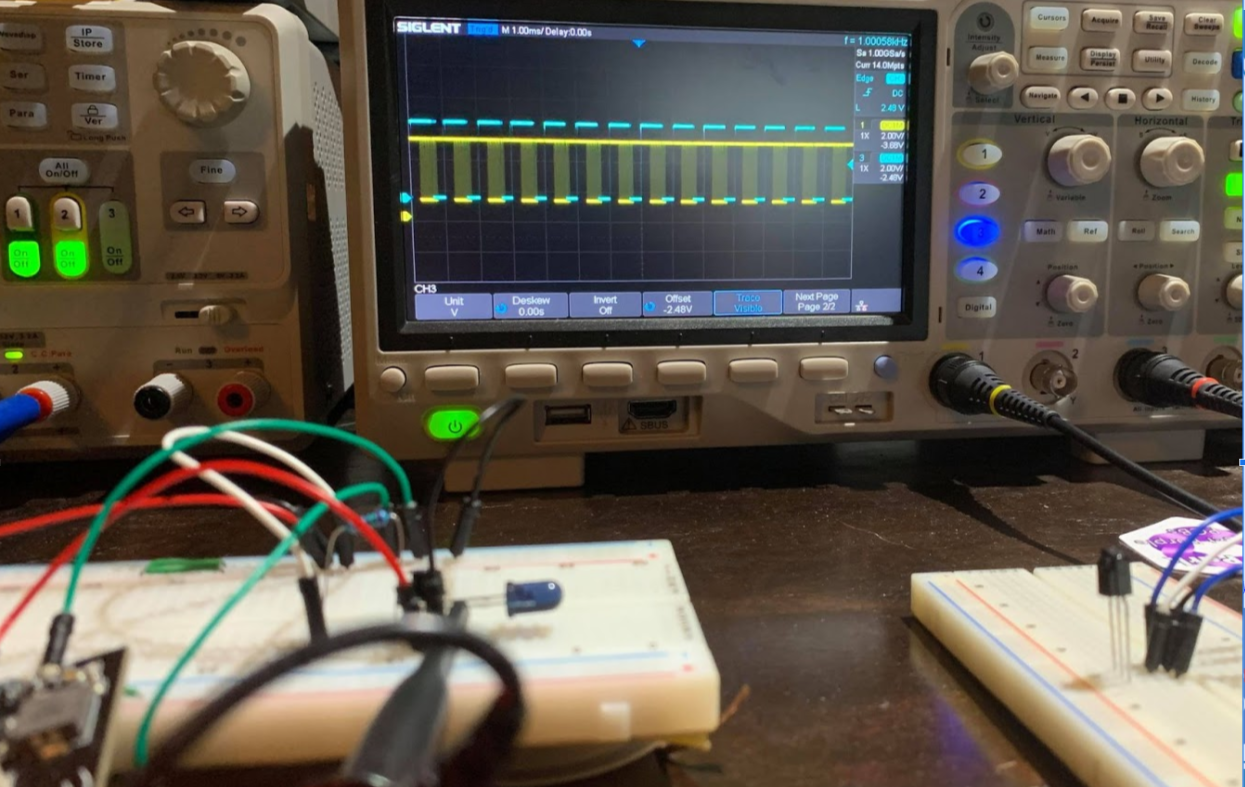
Figure 3 IR Emitter Testing
Figure 3 shows the IR Emitter Testing with the TSAL6100 and the TSSP58P38. The Oscilloscope shows the input signal to the TSAL6100 in yellow and the output of the TSSP58P38 in blue. As shown by the test the TSSP58P38 is able to detect the IR signal from the TSAL6100.
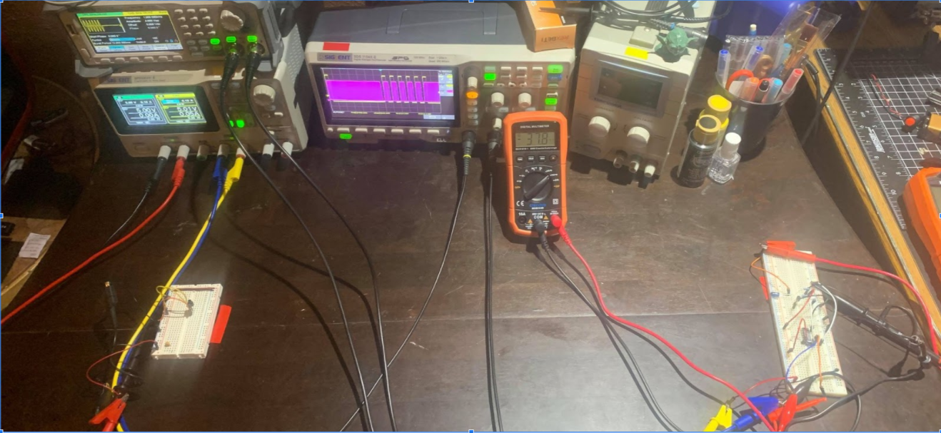
Figure 4 IR Emitter Testing at a Distance
Figure 4 shows the TSAL6100 and the TSSP58P38 testing again at a distance of 2ft. The multimeter shows that the current drawn from the IR Emitter is at 37mA which is nowhere near the theoretical max of 125mA, but the TSSP58P38 is still able to detect the IR pulses as shown by the oscilloscope.
32U4 Code
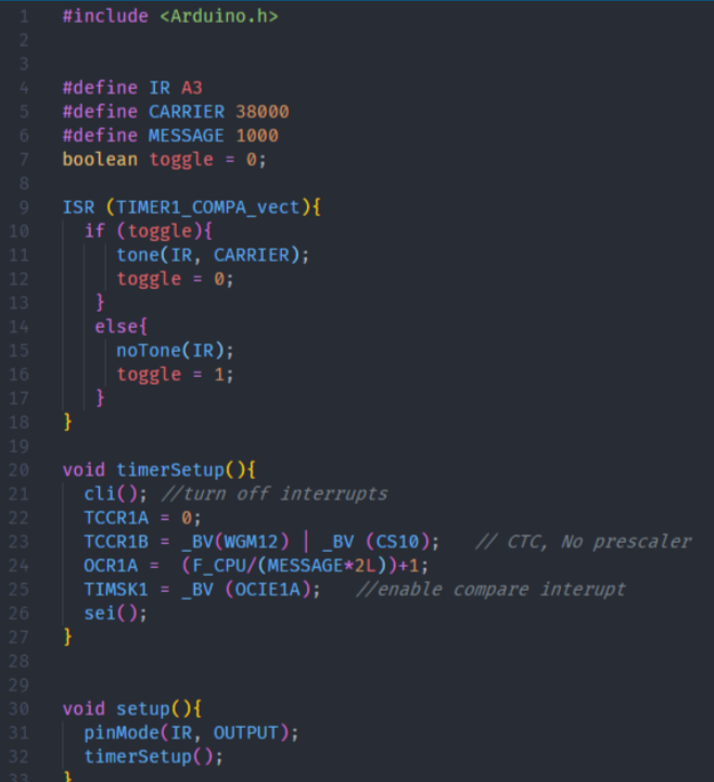
Figure 5 IR Emitter Code using timer interrupts on the 32U4
Figure 5 shows the IR Emitter code using the timer interrupt on the 32U4 and the tone built-in library to bit-bang the IR pin in order to pulse the IR emitter. The timer setup function setups the hardware interrupt timers to trigger the ISR.
Conclusion
In conclusion, the TSAL6100 and TSSP58P38 worked well in combination. The TSSP58P38 was able to detect the TSAL6100 IR pulses at over 2ft with only a max current output from the TSAL6100 of 38mA.