Mini-Pathfinder Spring 2017 Preliminary Design Document
Martin Diaz (Project Manager)
Adan Rodriguez (Mission Systems and Test)
Moses Holley ( Electronics and Control)
John Her ( Manufacturing – Chassis)
Edgardo (Manufacturing – Solar )
Table of Contents
Program Objective/Mission Profile
Objective
By Martin Diaz (Project Manager)
The Mini-Pathfinder will follow and support a walking robot in a to-be-negotiated Battle. The Mini-Pathfinder will autonomously follow it’s respective robot and provide video support. An operational solar polar will also be used by the Mini-Pathfinder.
http://web.csulb.edu/~hill/ee400d/S%2717%20Project%20Objectives%20and%20Mission%20Profile.pdf
Requirements
Level 1 Requirements
By Martin Diaz (Project Manager)
- L1-1 Mini Pathfinder shall be completed by Friday, May 19, 2017 (According to CSULB final exam schedule)
- L1 -2 Mini Pathfinder shall use a 3Dot Board Microcontroller with a custom SMD l2C shield.
- L1 -3 Mini Pathfinder shall provide video support by keeping its respective robot in view. (At a distance to be specified by customer.)
- L1 -4 Solar Panels on the Mini Pathfinder shall power a led.
- L1-5 Solar Panels should charge the battery of the Mini Pathfinder.
- L1-6 Mini Pathfinder shall be capable of autonomous operation.
- L1-7 Mini Pathfinder will also have the ability to switch from autonomous to being remote controlled, by Arxterra application or control panel, in event of autonomous system failure.
- L1-8 Mini Pathfinder shall be scaled in size to the Sojourner Rover. (Scale to be determined by customer)
Level 2 Requirements
By Adan Rodriguez
- L2-1 Mini Pathfinder Chassis shall hold 3Dot Board within its Chassis,
- L2-2 Mini Pathfinder shall use 6 motors to drive the 6 wheels.
- L2-3 Mini Pathfinder shall use a LG k10 phone for the camera system.
- L2-4 The dimensions of the rover should be 170.16mm(L)x125.66mm(W)x78.54mm(H).
- L2-5 The dimensions of the rover will be 1:3.82. scale to the soujouner
- l2-6 The motors shall be inside the wheels and thus not exceed a diameter of 27.86mm.
- L2-7 The Mini Pathfinder shall utilize ultrasonic sensors to track it’s lead robot.
Creative Solutions
By Martin Diaz (Project Manager)
During our brain writing exercise we were tackling the problem of what video system will we use and how will we implement it. Several cameras were chosen and we reviewed the pros and cons of each. We choose to try our camera phone since it has capabilities of using the arxterra app and wifi capabilities to send the video. But we quickly ran into the problem of how and where will it be placed on a small chassis. A standing phone will not work because it would interfere with solar panel placement and will not be a model of the sojourner. We concluded to have a layered structure with a phone sandwiched between solar panels and the chassis. The chassis will hold the electronics and the phone will use a periscope to achieve a forward looking view from the rover.
Another possible solution that we realized during our different perspective exercise was tracking a color or led on the lead robot. This idea came up after viewing our task through nature’s point of view and imagined a mouse looking for cheese. This solution will need further research.
System Design
Work Breakdown Structure
By Martin Diaz (PM) and Adan Rodriguez (Mission and Systems)
The WBS shows what work is assigned to each division. Mission Systems is assigned to work on arduino program and arxterra control. Manufacturing is assigned to use CAD software to design the rover. ENC is assigned to make the schematic of the custom PCB.

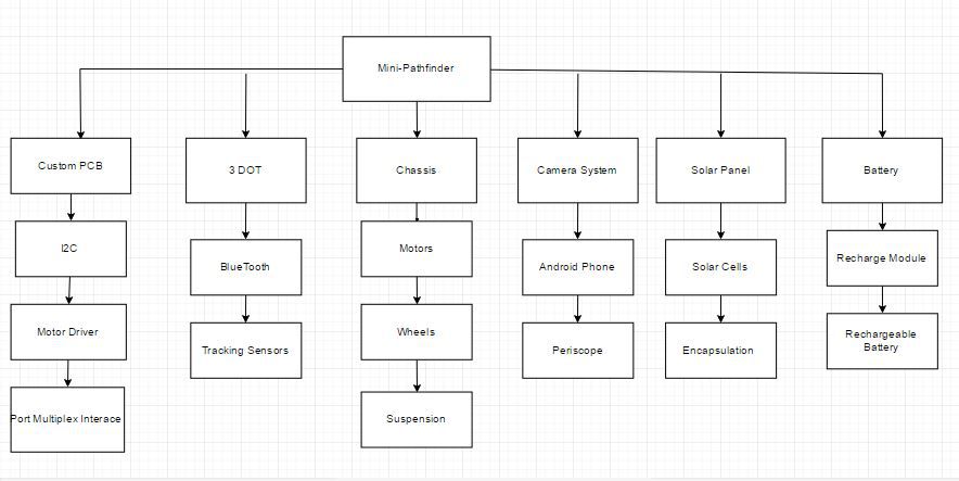
Product Breakdown Structure
By Adan Rodriguez (Mission and Systems) and Martin Diaz(PM)
The PBS shows the components parts or finished product of each system. The diagram shows the components of what the chassis, 3Dot board and custom PCB, etc. will contain.
Electronic Design
System Block Diagram
by Adan Rodriguez (Mission, Systems, and test)
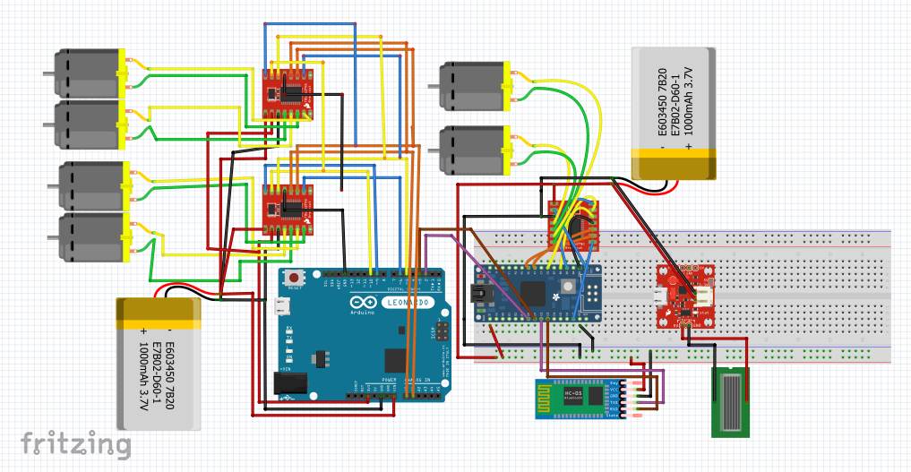
We plan to use the motor controller on board the 3Dot. Due to our rover needing 6 motors a expansion board will be needed. Expansion board is going to be our custom PCB that will contain 2 more motor controllers and interface with our sensors. Bluetooth will connect to a phone for manual control. Solar panel will connect to our battery to charge.

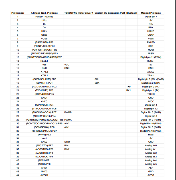
Interface Definitions
By Moses Holley (Electronics and Control)
Fritzing Diagram
By Moses Holley
Sources
- https://learn.sparkfun.com/tutorials/tb6612fng-hookup-guide
- https://www.arduino.cc/en/Hacking/PinMapping32u4
- https://cdn-learn.adafruit.com/downloads/pdf/atmega32u4-breakout.pdf
- http://duino4projects.com/wp-content/uploads/2013/04/
- http://Ardunio_leonardo_pinout.jpg
- https://www.arduino.cc/en/Reference/Wire
Mechanical Design
by John Her (Manufacturing – Chassis)
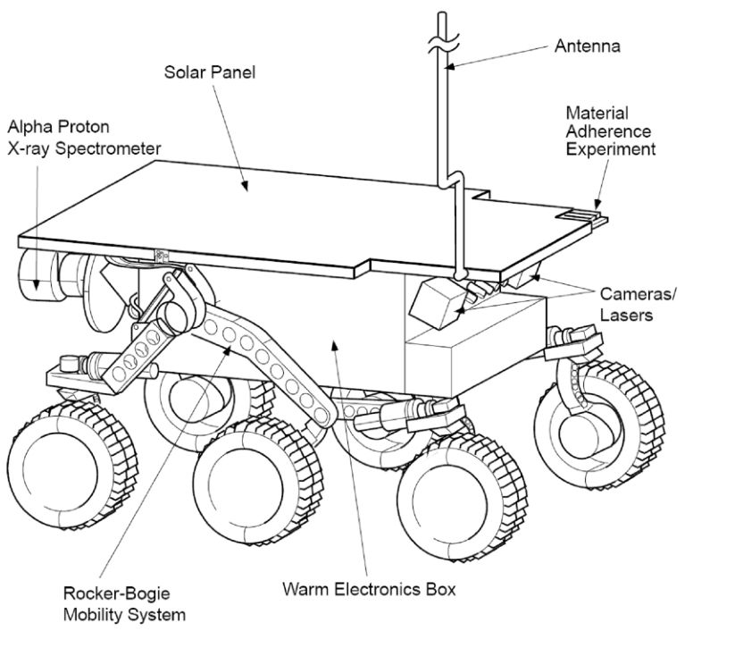
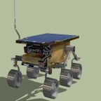
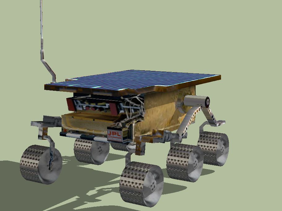
The design of our rover will follow the Sojourner rover of the Pathfinder mission. It will be a scale sized model encompassing the 3dot board within the chassis. It will continue to utilize the rocker bogie suspension and will have six motors driving the six wheels. The Sojourner rover has dimensions of 65cm(L)x48cm(W)x30cm(H) [1]. The 3dot board is 69mm(L)x35mm(W) [2] and will be enclosed within the chassis. We will also be using a smart phone as the camera system. The smart phone we will be using is the LG K10 phone which has dimensions of 146.6mm(L)x74.8mm(W)x8.8mm(H) [3]. The scale model will be as small as possible to fit the dimensions of the 3dot board. Since it has to be to scale, it can only be as small as our largest part. In this case, the phone will be our largest part. The phone will lay flat underneath the solar panel array and above the chassis containing the electronics, including the 3dot board. The Sojourner rover uses solar cells that are 4cm(L)x2cm(W) [4] that are arranged to fit in a 14(L)x18(W) array.
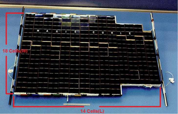
Multiplying the lengths and the widths gives the total length of 4cm/cell*14cells = 56cm and width of 2cm/cell*18cells = 36cm wide. This gives a length to width ratio (56/36=1.556) of 1:1.56. Given the length of the cell phone is 146.6mm, a scaled down solar panel of the Sojourner with the same length will have to be 94.243mm wide which is 19.443mm wider than the phone at 74.8mm. Due to the scale of our rover, an exact replica of the solar array may not be possible and may have to just be a full rectangle shape. If we are to compare the size of the solar array from the Sojourner rover and compare it to what will fit over the phone, we can obtain our scale for our rover model which is (560mm/146.6mm = 3.819) 1:3.82. Using this scale, the dimensions of our rover should be 170.16mm(L)x125.66mm(W)x78.54mm(H). Looking at the size of the wheels [5] of the Sojourner rover, we can see that it has a wheel diameter of 137mm and a width of 60mm. If we apply the scale of our rover (137mm/3.82), it gives us a wheel diameter of 35.86mm and a width (60mm/3.82) of 15.71mm. If we make the wheels have a 2mm thickness with 2mm of clearance for the motors, this gives us the option to use a motor of at most a diameter of 27.86mm since the motors will be in the wheels. To determine the size of the chassis containing the electronics, a replica paper model was printed and measured [6]. Looking at the 1:15 scale version of the model, the solar cell array was measured at 57mm(L)x43mm(W) and the chassis was measured at 39mm(L)x27mm(W)x17mm(H). The length of the chassis is 1.46 times smaller than the solar array and the width is 1.59 times smaller. When comparing the length of paper model of the chassis to the height, the height of the chassis is 2.294 times smaller. If we apply these scales to our determined solar panel size of 146.6mm(L)x94.243mm(W) then the length and width of our chassis should be 100.3mm(L)x59.18mm(W). Then comparing the length of the of this (100.3mm) to the height, 2.294 times smaller, then the height of the chassis should be 43.72mm(H). These dimensions for the chassis should provide enough clearance to contain the 3dot board.
Sources
- http://solarsystem.nasa.gov/missions/pathfinder/indepth
- https://www.arxterra.com/3dot/
- http://www.phonearena.com/phones/LG-K10_id9838
- https://mars.jpl.nasa.gov/MPF/roverpwr/power.html
- http://www.kiss.caltech.edu/workshops/xterramechanics2011/presentations/lindemann.pdf
- http://jleslie48.com/jj_sojourner/SojournerRover_PaperModel.pdf
Design and Unique Task Description
Encapsulation Trade Off Study
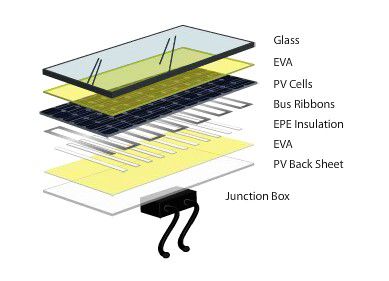
by Egardo Villalobos (Manufacturing – Solar)
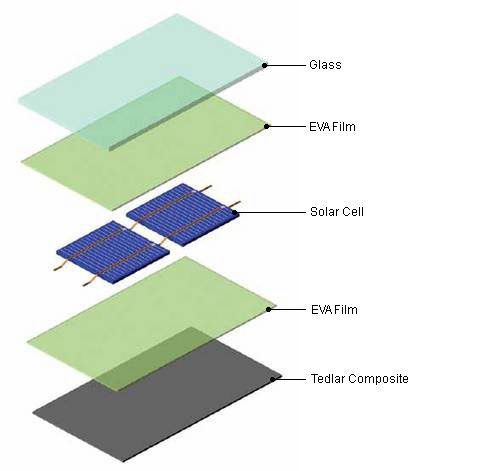
As the Manufacturing Engineer for the solar panels on the Mini Pathfinder, I am required to come up with a solution in in powering an LED on the Mini Pathfinder and, if possible, to fully power the Mini Pathfinder. Another thing we want to work on is the solar cell encapsulation because we’d like to find a way to make these cells modular so that a cell can easily be replaced.
PLEXIGLASS
Plexiglass provides a lightweight, anti-reflective surface and is classified as a scratch resistant surface. Although plexiglass is virtually impossible to break and scratch resistant, it can scratch much easier than glass. If this material is used to encapsulate the solar cell, we’d be able to acquire it from Home Depot or other similar store. This glass would then be used to cover the panel. To get the right shape out of the glass, we could use a dremel grinder to cut to size. The size of the glass would be the same size as the panel, which still need to be measured. The downside to using plexiglass is that the solar cell needs to be sandwiched using other materials, such as resin, which costs the same as buying one already encapsulated.
Source:
- Plixiglass http://www.plexiglas.com/export/sites/plexiglas/.content/medias/downloads/sheet-docs/plexiglas-optical-and-transmission-characteristics.pdf
- Materials http://sinovoltaics.com/learning-center/materials/ethylene-vinyl-acetate-eva-film-composition-and-application/
- Materials http://www.dunmore.com/products/solar-back-sheet.html
EPOXY COVERED SOLAR CELLS
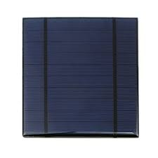
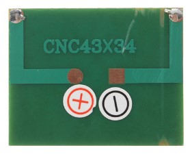
Solar cells could be bought already encapsulated with a UV resistant epoxy and are usually meant to charge phones and other toys. Each cell is independently encapsulated making it easier to remove and add new cells. These cells are also polarity based, which could require wires instead of tabbing wires, also making it easier to switch cells. Using these cells would cost about the same as buying all the materials, using the plexiglass sandwich method.
Sources:
ENC Task
- Experiment with motors to obtain torque ratings.
- Build breadboard circuit for PCB testing.
- Update Fritzing diagram
Manufacturing Task
- Build or simulate Prototype
- Solar Panel Prototype
Mission and Systems Task
- Work on arxterra application and arduino program.