Mini-Rosco Spring 2020
Mini-Rosco Ultrasonic Distance Testing
Author/s: Alex Margaris & Giann Bullo
Table of Contents
Introduction
Mini-Rosco’s mission employs the use of a single, front facing, mounted ultrasonic sensor. In order to ensure that Mini-Rosco’s automated drive mode included a means of avoiding obstacles. Mini-Rosco not only utilizes this ultrasonic sensor for a means of detecting obstacles, but also as a means of following other robots or objects.
This blog post will show some programming and distance testing that was done with the ultrasonic sensor to ensure that it was properly configured for Mini-Rosco’s mission. It should be noted that the prerequisites to this include the following: an ultrasonic sensor, wires, the 3DoT board, and a computer with the Arduino IDE installed.
Model of Ultrasonic Sensor Used
For the ultrasonic sensor, the Mini-Rosco team chose to use the US-100 from Adafruit for its 3V- 5V power requirement and its two modes (“HC-SR04” and “Serial UART”) for serial communication. A tradeoff study with more details on the selection can be found here
The US 100 is connected to the 3Dot via the MOSI and MISO pins. The reason for this is because any serial communication that isn’t being utilized on the 3Dot can be repurposed as digital pins. So the MOSI and MISO pins can be re-configured as UART as long as the pins are being called in the arduino code. The reason that we chose to use MOSI and MISO is because the team decided to use only one ultra sonic sensor to detect objects. It will then be controlled via pan to sense any objects in front of it. Our first option was to connect three ultra sonic sensors via I2C to detect the objects. This, however, became a problem due to the fact that we would have to find different types of the ultrasonic sensors since buying the same type would use the same I2C address. This would make things even more complicated for the project and the time and effort to research this becomes not worth it. Another reason was that ultrasonic sensors that use I2C are very expensive and would bring up the cost of the project to another 50 or 60 dollars. It was then we decided to connect the ultrasonic to the pins that aren’t being used on the 3dot and move using the pan system to have a larger sensor range. This solution saved the group a good amount of money and time.
Ultrasonic sensors work by sending out a sound wave at a frequency above the range of human hearing. The transducer of the sensor acts as a microphone to receive and send the ultrasonic sound. Our ultrasonic sensors, like many others, use a single transducer to send a pulse and to receive the echo. The sensor determines the distance to a target by measuring time lapses between the sending and receiving of the ultrasonic pulse. With this information it is possible to configure the robot to move toward an object if it is detected.
Testing using the Arduino IDE Serial Display
When testing the ultrasonic sensor via the 3Dot we found the objects that the sensor detected was only when it was directly in front of it. If the object would move out of its range which isn’t too big to begin with, then the sensor would not detect anything. According to the manufactures website the measuring angle is less than 15°. This poses a major problem due to
the fact that our object that we are trying to detect will be constantly moving. If it loses sight then the robot won’t be able to follow it. The solution that the team came up with was to create a holder for the ultrasonic sensor that is attached to the pan system of the robot. This would allow the ultrasonic sensor to have a wider range and detect almost anything in front of it without it losing sight of the object. Below is a picture of the serial monitor and how far the object is from the sensor. I held up a a piece of paper and slowly brought it close and close to the sensor. It can read from 3 cm up to almost 200 cm as long as the object is big enough to bounce the signal back. The video above demonstrates the small detection range of the sensor. When I got out of direct range and moved to the side it would not detect the piece of paper.
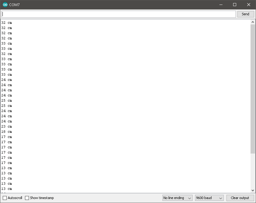
Figure 1: Ultra Sonic Sensor Serial Monitor
Distance Test Programming
This section of the blog post will go into detail on the methods used within the Arduino IDE to calculate and process distance using the US-100 ultrasonic sensor. Please note that the method used for calculating distance was NOT created by Mini-Rosco and all credit goes to Jsvester and as such will not be listed in this blog post to avoid taking credit for another person’s original work. However, the method and algorithm used for obstacle avoidance and following was created by Mini-Rosco and as such will be the focus of this section of the blog post.
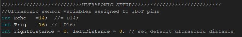
Figure 2: Ultrasonic Sensor Variables
As seen in the figure above, the ultrasonic sensor must be initialized before it can be read by the 3DoT board. The ultrasonic sensor used by Mini-Rosco utilizes two digital pins for data collection: “echo” and “trig”. The trig pin is responsible for creating a sound. The echo pin is responsible for receiving that sound once it bounces back.
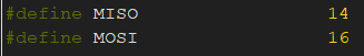
Figure 3: MOSI and MISO Initialization
In the Figure above, it is shown that the MOSI and MISO pins on the 3DoT will be used to interface with the ultrasonic sensor. This is important to note that traditionally, these are SPI pins on the 3DoT board. However, due to the 3DOT’s excellent design, which allows for high customization, the MOSI and MISO pins on the 3DoT can be repurposed to be used for UART interfaces. In addition, the MOSI and MISO pins must also be defined in the ‘void setup()’ part of the code as seen below.
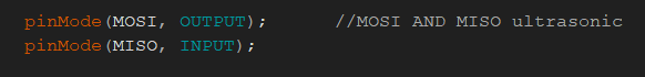
Figure 4: MOSI and MISO in void setup()
Following Logic
The logic present in our object following algorithm is similar to the logic used in Mini-Rosco’s obstacle avoidance algorithm. While there are slight variations, the overall logic and structure is the same. This was already created and described in detail in another blog post. Therefore, this blog post will not go into great detail about the creation of this logic. For more information on this, please Click Here.
The figure below demonstrates how Mini-Rosco was able to utilize the ultrasonic sensor in order to follow objects in front of it. The basic principles behind this are that the ultrasonic takes a measurement and the data is processed in the distance test mentioned in the code. Depending on the distance measured, Mini-Rosco will then have move commands written to its motors. It should be noted that this implementation also utilizes Mini-Rosco’s Automated mode. More can be read about Mini-Rosco’s automated mode here.
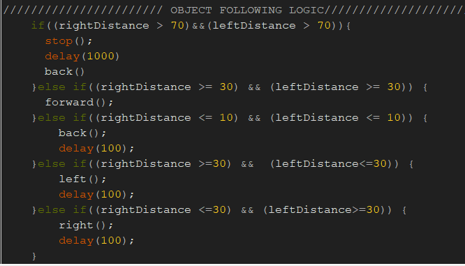
Object Following Code
Conclusion
In conclusion, Mini-Rosco utilizes an ultrasonic sensor that must be panned left and right in order to gain accurate readings of Mini-Rosco’s surroundings. The testing of the ultrasonic sensor has proven to be successful and is a major component in the completion of Mini-Rosco’s Mission.