Goliath Fall 2017 – Gyro and LED Custom PCB

The custom printed circuit board was designed to include both the gyro sensor and the LED display on the top panel. The LED will display the direction the tank is taking within the maze. By working with my project and division manager the schematic and layout were created on Eagle CAD. The files were not […]

Goliath Fall 2017 – APP Setup and Remote Control User Guide

The goal of this guide is to provide setup for the custom commands needed on the Arxterra APP side in order to control the Goliath running the final code. Secondly, this guide will provide instructions on how to control the goliath correctly from the commands defined.

Goliath Fall 2017 – LED Grid Display

Based on our L1 requirements to have a LED display and the L2 sub-requirements to indicate the next turn direction, having an LED grid display was a stretch goal. After some (what turned out to be pretty simple work) the LED proves very useful in indicating to the user the intended direction when user input is […]

IR shield Fabrication and Test

IR shield Fabrication and Test

Written by Charles Banuelos(Division Manager Design and Manufacturing) & Muhannad Al Mohamed(Division Manager E&C)

Approved by  Charles Banuelos(Division Manager Design and Manufacturing), Muhannad Al Mohamed(Division Manager E&C), Mark Huffman(Project Manager Goliath), Zach Oyog (E&C Sojourner)

Fabrication

Fabrication of the 3DoT IR shield occurred on 12/5/2017 due to the fact that Color Sensor Shield fabrication was not able to be completed. There was no stencil available to use to solder the IR shield; therefore, hand soldering is needed. The IR sensors themselves where placed flushed to the board to ensure that the IR sensors do not come contact the ground during the mission.

The fabrication process did have some setbacks while soldering parts. The first major set back was placing the surface mount parts on top of the IR shield without using the pick and place machine. The lack of the pick and place machine caused many dead joints at surface mount parts due to improper placement. The other setback was the actual look of the solder themselves and many needed to be redone due to none uniformity.

Test

Testing the IR shield was done by applying an Arduino code to it. Since the IR shield uses the six pins of the front header of the 3DoT board (A2,A3,SDA,SCL,3.3V VCC,GND), the code optimizes direct reading from the pins using Arduino’s built in read function. The used code was applied to a 3Dot board to ensure a proper running of the sensors. The test revealed that we were successful on fabricating four shields out of five. The fifth IR shield will be taken back to fab to ensure that all are working.


Placing components during Fabrication of the IR sensor shield

Update 12/7/2017

The following code is used to test the distance measurement for each IR ICon the 3DoT IR shield.

Update: 12/15/2017

The following code was altered by changing the reading commands from “analogRead” to “digitalRead.” The reason for this change was because the SDA and SCL pins are not actually analog pins, thus, the function “analogRead” would not return actual measurements. Therefore, the command “digitalRead” was used instead to get binary inputs as an indication that the pins are actually working.

Code :

////////////////////////////////////////////////////////////////
//  Name     : 400D IR Shield Testing Code                    //
//  Author   : Muhannad Al Mohamed                            //
//  Date     : 5 December, 2017                               //
////////////////////////////////////////////////////////////////
 
 //defining variables to save measurements
 int farRight_IR;
 int innerRight_IR;
 int innerLeft_IR;
 int farLeft_IR;
 
 void setup()
 {
 
   Serial.begin(9600);
 
   pinMode(A3,INPUT);      //Top view, pins up, far right IR sensor
   pinMode(SDA,INPUT);     //Top view, pins up, second right IR sensor
   pinMode(SCL,INPUT);     //Top view, pins up, second left IR sensor
   pinMode(A2,INPUT);      //Top view, pins up, far left IR sensor
 
 }
 
 void loop()
 {
 
  //reading values of IR sensing into variables
  farRight_IR = digitalRead(A3);
  innerRight_IR = digitalRead(SDA);
  innerLeft_IR = digitalRead(SCL);
  farLeft_IR = digitalRead(A2);
 
  //printing measurments in searial monitor
  Serial.print("farRight_IR =  ");
  Serial.print(farRight_IR);
  Serial.print("  ");
  Serial.print("innerRight_IR = ");
  Serial.print(innerRight_IR);
  Serial.print("  ");
  Serial.print("innerLeft_IR = ");
  Serial.print(innerLeft_IR);
  Serial.print("  ");
  Serial.print("farLeft_IR = ");
  Serial.println(farLeft_IR);
 
 
  delay(250);
 }

Read more

Goliath Fall 2017 – Post PDR Adjustments and 3D prints

After taking a closer look at the IR sensor, I realized that the sensor needed to be relocated to avoid contact with the first motor. The distance between the top panel and the front motor is not large enough to fit the sensor. Although we did consider redesigning the top, the tank will lose its […]

ModWheels Electronic Breadboarding

By: Matt Shellhammer (Electronics & Control Engineer)

Approved by: Lucas Gutierrez (Project Manager)

Introduction

To create a baseline design that can be used for testing and software development an electronic breadboarding of ModWheels was constructed. All components were breadboarded using some components that will not be used on the day of the final that are being used for prototyping and testing. This allows us to do testing on all of our components and ensure that our wiring diagrams are correct as well as confirming that all of our components work together properly and the software is developed appropriately for the electronic components in use.

Methodology

To perform this electronic breadboarding a Sparkfun Pro Micro and a Sparkfun TB6612FNG motor driver was used to imitate the 3DoT v5.03 board. Then all external components were connected to these two central components.

Components breadboarded:

  • I2C Multiplexer (TCA9548A)
  • Two Color sensors (TCS34725) (Through I2C Mux)
  • IR Proximity sensor (VL6180) (Through I2C Mux)
  • Two GM6 Extended Shaft Motors
  • Two Magnetic Quadrature Hall Effect Encoders
  • Micro Servo

The breadboarding was first done without the ModWheels chassis to test the breadboarding and software first. This was done connected printing data to the Serial print monitor from the Arduino IDE. The breadboarding done without the ModWheels chassis and serial print monitor is shown below in Figures 1 & 2. The motors were programed to stop when the proximity sensor was lower than 6 inches (~153 mm) but otherwise to continue spinning.

Figure 1. Electronic breadboarding without ModWheels chassis.


Figure 2. Serial print monitor showing sensor readings (color sensors, encoders, IR proximity sensor)


 This breadboarding was then implemented within the ModWheels chassis to test the motors and proximity sensor together. Since it is programmed to stop within 6 inches of an object the car should stop and then continue when that object is moved. The breadboarding can be seen below in Figure 3 and the testing can be seen in Video 1.

Figure 3. Electronic breadboarding with ModWheels chassis.


Video 1. Testing of IR proximity sensor with GM6 motors and ModWheels chassis.

Software

ElectronicBreadboarding.ino

////////////////////////////////////////////////////////////////
//  Name     : Electronic Breadboarding                       //
//  Author   : Matt Shellhammer                               //
//  Date     : 3 December, 2017                               //
//  Version  : 1.0                                            //
////////////////////////////////////////////////////////////////

#define __PROG_TYPES_COMPAT__
#include <avr/pgmspace.h>
#include <Wire.h>
#include "Adafruit_TCS34725.h"
#include "EBB.h"
#include <Configure.h>
#include <FuelGauge.h>
#include <Motor.h>
#include <Packet.h>
#include <Robot3DoTBoard.h>
#include <TB6612FNG.h>
#include <TelecomClass.h>
#include <Watchdog.h>
#include <SparkFun_VL6180X.h>

// Define motor driver pins
#define AIN1 14 // Pro-micro pin 14 (PB3)
#define BIN1 7  // Pro-micro pin 7  (PE6)
#define AIN2 4  // Pro-micro pin 4  (PD4)
#define BIN2 8  // Pro-micro pin 8  (PB4)
#define PWMA 5  // Pro-micro pin 5  (PC6)
#define PWMB 6  // Pro-micro pin 6  (PD7)
#define STBY 9  // Pro-micro pin 9  (PB5)

// Address for I2C multiplexer
#define TCAADDR 0x70

// Define Color sensors using library
Adafruit_TCS34725 colorSensor = Adafruit_TCS34725();

// Define IR proximity sensor using library
#define VL6180X_ADDRESS 0x29
VL6180xIdentification identification;
VL6180x sensor(VL6180X_ADDRESS);

// Define Servo
int8_t pos = 115;     // servo position
#define servo_pin 10  // (PB6)

// Define Encoders
#define LME A0  // Left motor encoder
#define RME A1  // Right motor encoder

void setup() {
  // put your setup code here, to run once:
  Serial.begin(9600);
  // DDRx & PORTx for motor drivers
  DDRD |= (1<<PD4)|(1<<PD7);
  DDRE |= (1<<PE6);
  DDRB |= (1<<PB3)|(1<<PB4)|(1<<PB5);
  DDRC |= (1<<PC6);
  // Pinmode for Servo
  DDRB |= (1<<PB6);

//  if(sensor.VL6180xInit() != 0){
//    Serial.println("FAILED TO INITALIZE"); //Initialize device and check for errors
//  };
//  sensor.VL6180xDefautSettings(); //Load default settings to get started.
}

void loop() {
  static bool IRflag = false;
  static color_t colorL;    // create an instance of color_t called colorL (left color sensor)
  static color_t colorR;    // create an instance of color_t called colorR (right color sensor)
  static uint8_t IR = 0;    // create variable for IR proximity sensor
  static bool LMEV;  // Left motor Encoder value
  static bool RMEV;  // Right motor Encoder value
  static uint16_t LMEV_count = 0;  // Left motor Encoder value count
  static uint16_t RMEV_count = 0;  // Right motor Encoder value count

  // Read Sensors
  colorL = readColor(0);
//  Serial.print("Left Red: "); Serial.print(colorL.r); Serial.print(" ");
//  Serial.print("Left Green: "); Serial.print(colorL.g); Serial.print(" ");
//  Serial.print("Left Blue: "); Serial.print(colorL.b); Serial.print(" ");
//  Serial.print("Left Clear: "); Serial.print(colorL.c, DEC); Serial.print(" ");Serial.println();
  colorR = readColor(1);
//  Serial.print("Right Red: "); Serial.print(colorR.r); Serial.print(" ");
//  Serial.print("Right Green: "); Serial.print(colorR.g); Serial.print(" ");
//  Serial.print("Right Blue: "); Serial.print(colorR.b); Serial.print(" ");
//  Serial.print("Right Clear: "); Serial.print(colorR.c, DEC); Serial.print(" ");Serial.println();
  IR = readIR(2);
//  Serial.print("Distance measured (mm) = ");Serial.println(IR);Serial.println("");

  while (IR < 153){          // Don't hit something
    analogWrite(PWMA, 0);
    analogWrite(PWMB, 0);
    IR = readIR(2);
    IRflag = true;
  }
  if (IRflag == true){
    delay(3000);
    IRflag = false;
  }
  // Move motors/servo
  forward();
  LMEV = digitalRead(LME);
  RMEV = digitalRead(RME);
  if (LMEV == true){LMEV_count++;}
  if (RMEV == true){RMEV_count++;}
//  Serial.print("LMEV_count: ");Serial.println(LMEV_count);
//  Serial.print("RMEV_count: ");Serial.println(RMEV_count);Serial.println("");
//  uint16_t count = 40000;
//  while(count > 0){
//    LMEV = digitalRead(LME);
//    RMEV = digitalRead(RME);
//    if (LMEV == true){LMEV_count++;}
//    if (RMEV == true){RMEV_count++;}
//    count--;
//  }
}

EBB.h

struct color_t{
  uint16_t r = 0; // Color sensor Red
  uint16_t g = 0; // Color sensor Green
  uint16_t b = 0; // Color sensor Blue
  uint16_t c = 0; // Color sensor Clear
};

EBBsub.ino

void tcaselect(uint8_t i) {
  //Selecting an address on I2C Mutiplexer
  if (i > 7) return;
  Wire.beginTransmission(TCAADDR);
  Wire.write(1 << i);
  Wire.endTransmission();
}

color_t readColor(uint8_t index) {
  color_t colors; // create an instance of color_t called colors
  // Read value from color sensor and determine reading
  tcaselect(index);
  colorSensor.begin();
  colorSensor.getRawData(&colors.r, &colors.g, &colors.b, &colors.c);
  return colors;
}

uint8_t readIR(uint8_t index) {
  // Read value from color sensor and determine reading
  tcaselect(index);
  uint8_t IR = sensor.getDistance();
  return IR;
}

void forward(){
  digitalWrite(STBY, HIGH);
  digitalWrite(AIN2, LOW);
  digitalWrite(AIN1, HIGH);
  digitalWrite(BIN1, HIGH);
  digitalWrite(BIN2, LOW);
  analogWrite(PWMA, 150);
  analogWrite(PWMB, 150);
  analogWrite(servo_pin,60);
}

void turn_right() {
  digitalWrite(STBY, HIGH);
  digitalWrite(AIN2, LOW);
  digitalWrite(AIN1, HIGH);
  digitalWrite(BIN1, HIGH);
  digitalWrite(BIN2, LOW);
  analogWrite(PWMA, 100);
  analogWrite(PWMB, 150);
  analogWrite(servo_pin,30);
}

void turn_left() {
  digitalWrite(STBY, HIGH);
  digitalWrite(AIN2, LOW);
  digitalWrite(AIN1, HIGH);
  digitalWrite(BIN1, HIGH);
  digitalWrite(BIN2, LOW);
  analogWrite(PWMA, 150);
  analogWrite(PWMB, 100);
  analogWrite(servo_pin,90);
}

void turn_around() {
}

void stopRobot(uint16_t d) {
  digitalWrite(STBY, HIGH);
  digitalWrite(AIN2, LOW);
  digitalWrite(AIN1, HIGH);
  digitalWrite(BIN1, HIGH);
  digitalWrite(BIN2, LOW);
  analogWrite(PWMA, 0);
  analogWrite(PWMB, 0);
  analogWrite(servo_pin,115);
  delay(d);
}

Rapid Prototyping, Motor Assembly, and Print Optimization

Written by Railan Oviedo (Manufacturing)

Table of Contents

Introduction

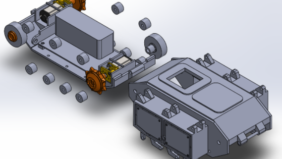
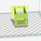
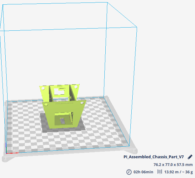
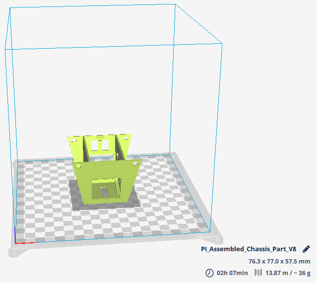
For this semester’s version of Pete-Bot, the rapid prototyping process involved the verification of being able to fit the motors and the 3DoT board inside a single 3D-printed chassis piece. Furthermore, after confirming that the base design was suitable for fitting the motors and the 3DoT board, the model itself would be altered in order to reduce print time. For information on the print time for each version, see the Print Time post.

Printed Version 1

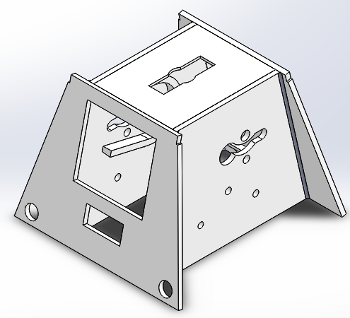
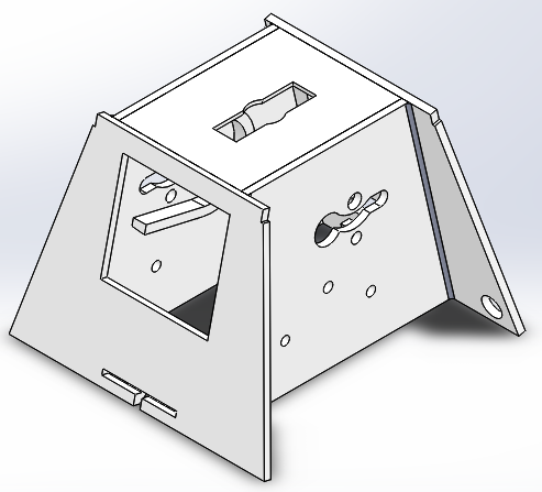
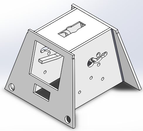
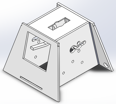
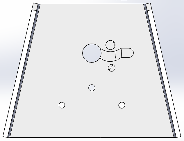
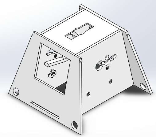
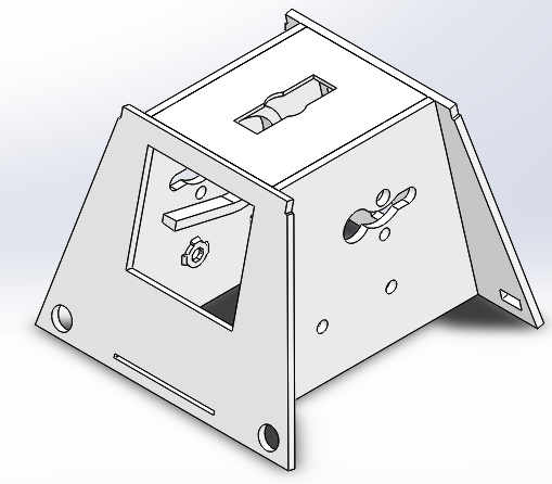
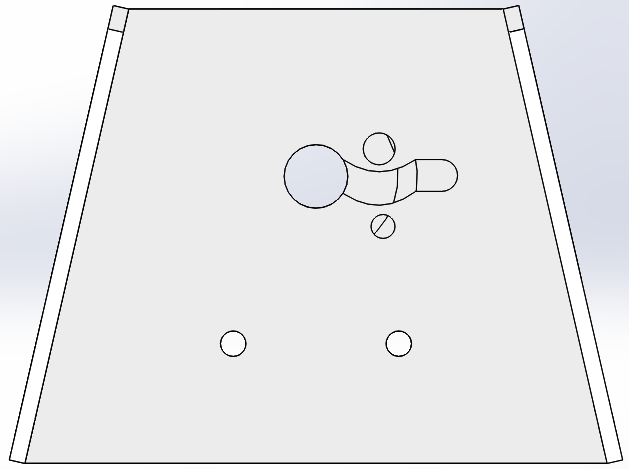
Shown are side-by-side views of the first version (Model vs. Printed Model). The chassis was printed through the use of Northrop Grumman’s 3D-printer thanks to the connections of a fellow student.

Figure One – Front View Side-by-Side

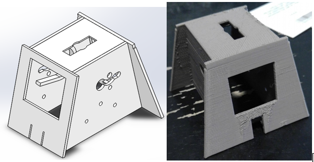
Figure Two – Back View Side-by-Side

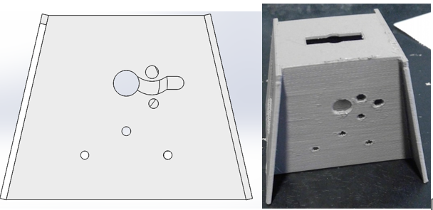
Figure Three – Side View Side-by-Side

Testing 3DoT Board Placement

The mechanism for placing the board in this version is the flap in the back side, which can be pulled to allow for the board to be pushed into the chassis. This was tested and confirmed to work; however, the flimsy nature of the flap caused it to break off of the model, which is why it cannot be seen in the pictures. As such, it was decided that a new mechanism will have to implemented for follow-up versions.

Testing Motor Placement

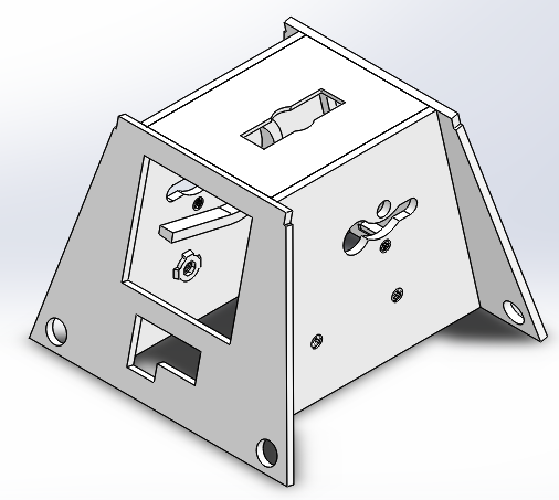
After attempting to fit the motors inside the chassis, it was found that they could not directly be placed inside with the current design. The 3D-model pictures were altered after printing the chassis, so they show the possible solution to allowing the motors to be placed inside.

Printed Version 2

The second version’s design is as follows. This was printed at the same Northrop Grumman source, but the printer experienced a malfunction mid-print so the chassis came out in a much less stable state than originally anticipated. All versions after this were printed through Ridwan.

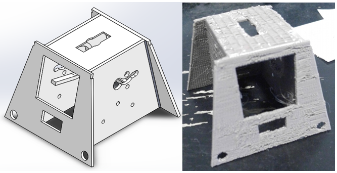
Figure Four – Front View Side-by-Side

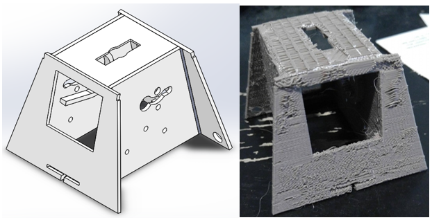
Figure Five – Back View Side-by-Side

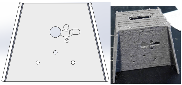
Figure Six – Side View Side-by-Side

Updates from Version 1

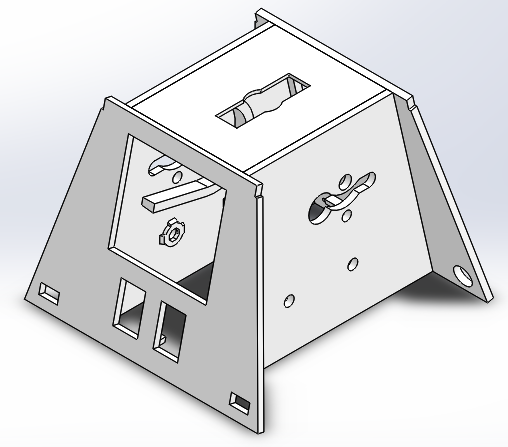
  • Pathway on the side has been made to allow the motors to be inserted into the chassis
  • Flap design has been altered so that there are now two small flaps that bend in the same direction of the printed layers
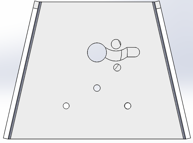
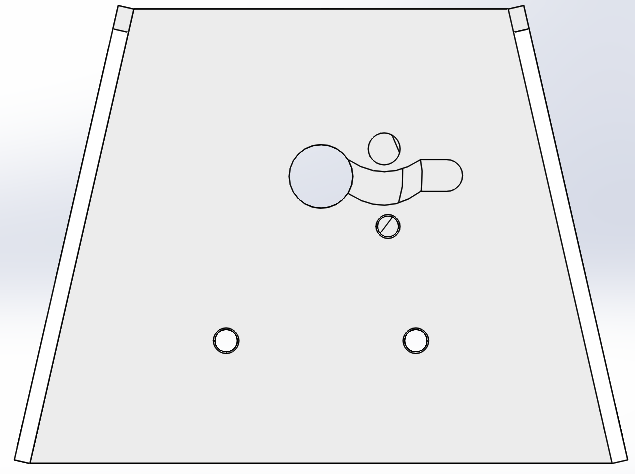
  • Holes were added to the bottom part of the front in order to allow the push-pins to have a place to be inserted. These push-pins will secure the paper shell to the chassis
  • Removed the two tiny holes in the front, as they were deemed to serve no purpose

Testing 3DoT Board Placement

This version still incorporates flaps of a sort, but the orientation has been switched. Instead, they bend towards the same direction of the printed layers, thus allowing for a stronger resistance to breaking. The board was once again confirmed to fit inside, but the flimsiness of the flaps were still notable, so further changes were made for future versions.

Testing Motor Placement

Despite the deformation of the design during the printing process, it was confirmed that adding the pathway between the holes allowed for both motors to be successfully inserted at the same time. From this version onwards, this part of the design remains the same since it properly performs its purpose and simultaneously leads to a lower print time.

Printed Version 3

As follows is the third design.

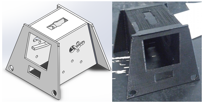
Figure Seven – Front View Side-by-Side

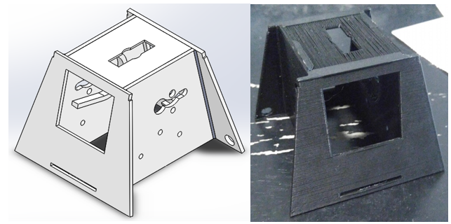
Figure Eight – Back View Side-by-Side

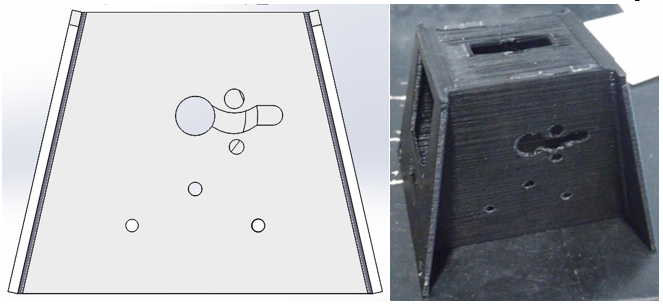
Figure Nine – Side View Side-by-Side

Updates from Version 2

  • Flaps were completely removed, in favor of making one section of the bottom somewhat separated from the rest of the chassis

Testing 3DoT Board Placement

After replacing the flaps with a small section of the chassis that can be pulled outward, it was found that this design is also sufficient in getting the 3Dot board placed inside. Furthermore, since no part of the chassis acts as a flap, the overall structure and security of the board in the chassis has increased. From all versions after this, the design for the 3DoT Board Placement will remain relatively the same.

Printed Version 4

The fourth design is as follows:

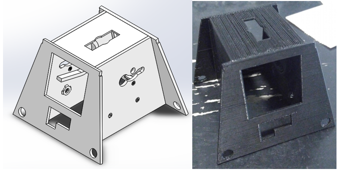
Figure Ten – Front View Side-by-Side

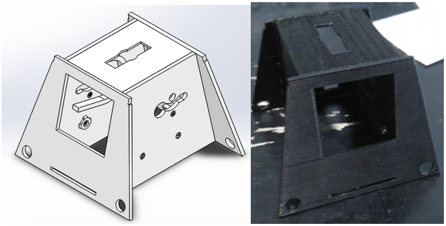
Figure Eleven – Back View Side-by-Side

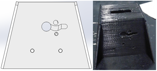
Figure Twelve – Side View Side-by-Side

Updates from Version 3

  • Structures have been put in place on the inside of the chassis to allow for stable screw placement for the gear system
  • Holes on the side of the chassis have been repositioned for gear testing

Testing 3DoT Board Placement

During this iteration of the chassis, it was discovered that the micro-USB port and the power switch attached to a fully aseembled 3DoT board were unable to fit within the previous design. As such, larger holes were placed in the front to allow these parts of the board to fit inside. However, after testing, it was found that these changes were not enough, so revisions to the front will be made for future versions.

Printed Version 5

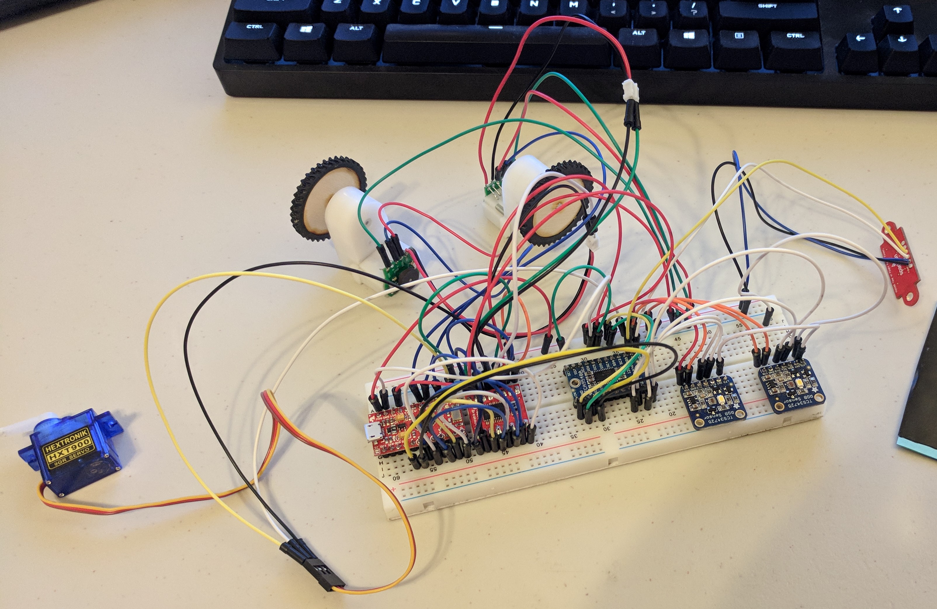
This version was the most recent upon the creation of this post, so it is photographed with the motors and unassembled 3DoT board in place.

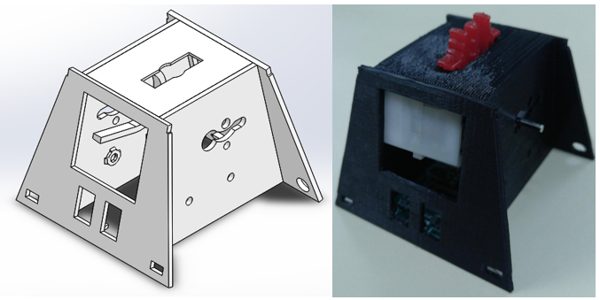
Figure Thirteen – Front View Side-by-Side

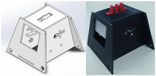
Figure Fourteen – Back View Side-by-Side

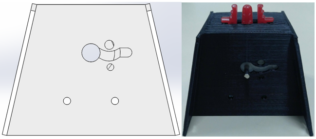
Figure Fifteen – Side View Side-by-Side

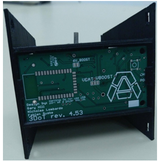
Figure Sixteen – Bottom View showing the unassembled 3DoT in place

Updates from Version 4

  • Because push-pins will only be inserted on the bak of the chassis, the front circular holes have been replaced with rectangular ones in order to accomodate a wooden platform that the castor wheel and color shield will attach to
  • The holes on the front have been expanded to allow for both the micro-USB port and the power switch to be inserted without hindrance

Testing 3DoT Board Placement

Despite the changes made to the front, it was found that the holes need to be even wider so that the fully assembled 3DoT can be placed inside. Besides this, no other design changes seem to be necessary.

Printed Version 6

This version is the latest as of December 12. It is pictured here with the planetary gear system, the wooden platform, and the castor wheel in place.

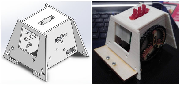
Figure Seventeen – Front View Side-by-Side

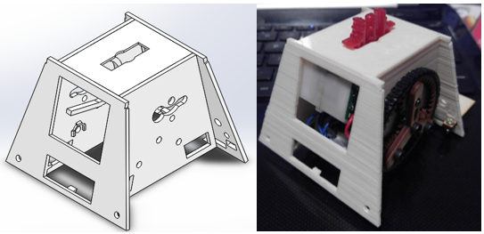
Figure Eighteen – Back View Side-by-Side

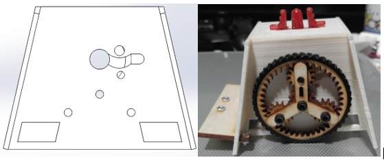
Figure Nineteen – Side View Side-by-Side

Updates from Version 5

  • After discovering that push pins are actually placed on the front, holes were put back in place to match their positioning with the paper shell’s holes for the push pins
  • The positioning for the micro-USB and power switch has been moved to the back of the chassis. Furthermore, the back has been opened up to allow for access to both without having to remove the board from the chassis
  • Rectangular openings have been made on the side of the chassis to make space for the SAMB11 board’s power switch
  • The round holes on the side of the chassis have been adjusted in such a way that the planetary gear system now functions perfectly
  • The front of the chassis has had holes put into it to accommodate a possible motion sensor. However, implementation of this sensor would result in having to cut out part of the paper shell
  • The front of the chassis has had its bottom partially removed to account for the front IR shield that will connect to the 3DoT. Slots have also been placed on the front of the chassis to allow the shield to snap into place

Testing 3DoT Board Placement

With this design, the fully assembled 3DoT was finally confirmed to fit inside. Attaching the IR shield to the board further increases its stability within the chassis due to the slots added to the front.

Wooden Platform

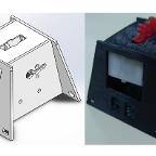
The design for the wooden platform began after it was confirmed that the fully assembled 3DoT with the shield could be placed in the chassis. The Solid Works image of the model is as follows:

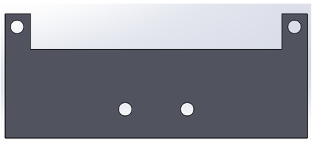
Figure Twenty – SolidWorks Model of Platform

After laser cutting the model out of wood, the assembled piece appears as:

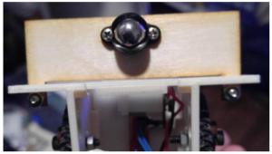
Figure Twenty-One – Bottom View of Wood Platform

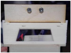
Figure Twenty-Two – Top View of Wood Platform

As shown in the pictures, both the castor wheel and wooden platform were confirmed to fit on the chassis. The platform is secured into its place with nuts and screws, and has the ability to slightly wiggle vertically in order to allow for better shock absorption for the castor wheel.
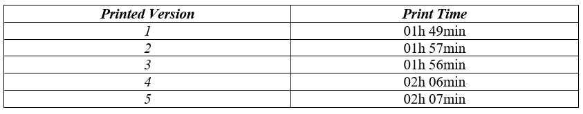
Summary Table

Table One – Table Showcasing Current Status

Goliath Fall 2017 – Requirements Update

1. Project Schedule – Project shall be ready by Wednesday, December 13th, 2017 2. Operational Task – The Goliath will have the functionality to be connected remotely using Arxterra 3. Toy – Elements – The Goliath will behave like a toy 4. Driving Surface – The Goliath will be able to drive on flat surfaces 5. Driving Surface – The Goliath shall […]

Pete-Bot (P-Bot) Print Time

Written by Railan Oviedo (Manufacturing)

Table of Contents

Introduction

For this semester’s version of the Paper-Bot (now dubbed “P-Bot”), one of the design requirements is to have the chassis 3D-printed as a single piece. After creating the 3D models, the approximate print time for the chassis are approximated through the use of Cura software. All print time estimations are made under the assumption that a Prusa i3 is used with the Coarse Quality (0.4 mm) and 20% infill. For information on the differences between the version, see the Rapid Prototype, Motor Assembly, Print Optimization post.

Cura Printing Setup

Figure One – Cura Printing Setup Screenshot

Printed Version 1

Figure Two – Front Isometric View

Figure Three – Back Isometric View

Figure Four – Side View

The Cura print time is shown as:

Figure Five – Version 1 Print Time

Printed Version 2

Figure Six – Front Isometric View

Figure Seven – Back Isometric View

Figure Eight – Side View

The Cura print time is shown as:

Figure Nine – Version 2 Print Time

Printed Version 3

Figure Ten – Front Isometric View

Figure Eleven – Back Isometric View

Figure Twelve – Side View

The Cura print time is shown as:

Figure Thirteen – Version 3 Print Time

Printed Version 4

Figure Fourteen – Front Isometric View

Figure Fifteen – Back Isometric View

Figure Sixteen – Side View

The Cura print time is shown as:

Figure Seventeen – Version 4 Print Time

Printed Version 5

Figure Eighteen – Front Isometric View

Figure Nineteen – Back Isometric View

Figure Twenty – Side View

The Cura print time is shown as:

Figure Twenty-One – Version 5 Print Time

Summary Table

Table One – Summary of Versions and Print Times