Eagle Cad Lecture series

Written by Charles Banuelos MFG DM

Table of Contents

Written 11/2/2017

The division has finished learning Eagle Cad. The first of the two tutorials covered moving of components in eagle cad along with switching to the PCB layout so that they may start to build. The second tutorial covered how to create traces and nets on the PCB. The lecture then covered what vias are and how to place them. The lecture followed with showing how that the use of both sides of the board which will make the designs of the PCB easier to come up with.  The lecture then went into how to use polygons. The part of the lecture that teaches polygons might be the most important of the whole lecture. The polygon function allows for the creation of power planes and ground planes. These planes can be a small square in the corner of the board or it can take up the whole board. The lecture continues with how to do DRC checks. The lecture then goes over how to get the .dru files from OSH park in order to use their checks so that the boards can be built. The lecture concludes with making the Gerber files. The lecture shows how to download OSH parks gerber file presets. This allows for all of the Division members to turn in the correct files to make their PCB’s.


Update 11/30/2017

The lectures below along with the quiz and supplemental material provided will be able to teach students how to create PCBs given they are already given the schematics.

EagleCad Training Part 1

-To start a New Project you must first either create a new schematic or open a schematic. To start a new schematic you first open eagle and then click on file in the upper left hand corner. Then click on new and then schematic. You will then be able to start populating the schematic work space.  To place parts you press on the add icon located on the left side of the work space.

This space is very extremely sensitive to both spelling as well as capitalization for parts.

To move the parts around the board you must press on the move button and then on the cross on each part to move the part. To rotate the components it is the same procedure but you must press the rotation button first.

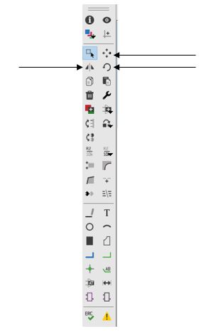
To connect the part you use the line or net button. If you would like two lines to branch from a single point or come to a single point you must use the junction button in the lower left corner.

Once the schematic is deemed correct it is time to create the PCB.  To open an already existing schematic go to file and then open. This allows you to open the correct file.

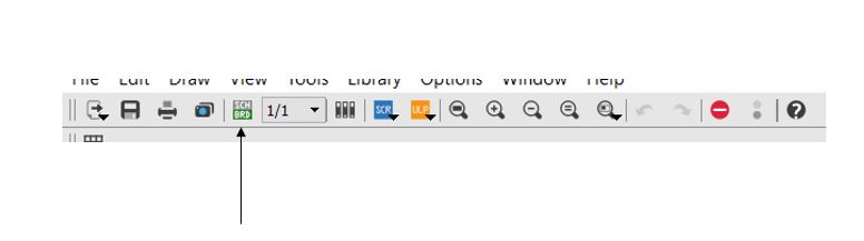
To create the PCB one must click on file and then on the button switch to board. To populate the board it is the same operation as the schematic. To move the parts click on the move tool and on the cross on the part. You will then be able to drag the part to the desired location.

EagleCad Training Part 2

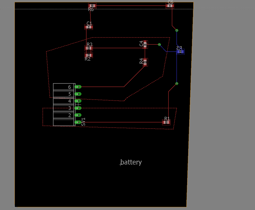
Once the board has been populated you be able to start creating traces. To create traces on the PCB the route tool on the left side of the work space must be used. To use this tool click on the route tool and then on the place you would like the trace to start.

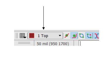
It is common practice to always use 45 degrees when designing PCBs. To view the angle of being drawn click on the route tool and then at top of the page you will see the different possible angles available. To finish a trace click on the point you wish to end the trace.


To place parts on the bottom layer of the board the person placing the parts will need a mouse or will need to click on the mirror button. To place parts on the bottom layer with a mouse the user will have to click on the move button and then on the part. Once the part has been clicked on the person will click on the mouse wheel which will make the part turn blue which means that the part is on the bottom of the board. The mirror button will also be able to do the same thing in the PCB work space.

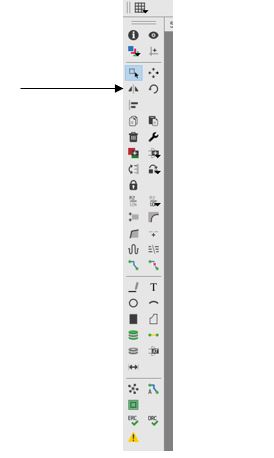
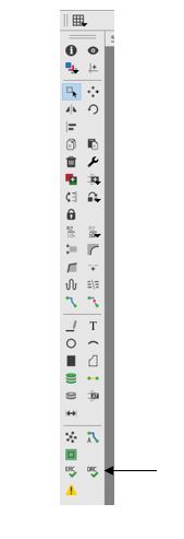
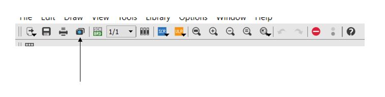
To run a trace to this part a via will need to be placed. The first way to place a via is too manually place the via using the via tool located towards the middle of the tool bar.

The second way to place a via to first run a trace to a certain point. The person will then click to stop the route but will still be able to draw a route. The user will go to the upper corner of the of the work space and click on the select layer drop down which is located next to the grid button. The user will select bottom layer which will create a via to which the top layer route will already be connected to. The user will then be able to continue the route in blue on the bottom of the board.


To remove an unwanted route the user must click on the rip up tool located next to the route tool.

To view all of the layers of the board you can click on the layers setting in the upper left corner of the work space.

To create polygons it is key to remember that  a polygon must start and end at the same point on the board. Polygons are useful in order to create power and ground planes for the whole board or specific portions of the board. Once created these can be moved or changed using the move tool. These polygons can be created on both the top and bottom layers using same layer selecting button. To name the polygon, the user must right click on the edge of the polygon and go to properties. The name of the polygon is case secretive and will be close to the bottom of the window. The naming of a polygon will allow for any part that is connected to that name to be automatically connected once the rat nest button on the bottom of the tool bar is collected. It is common practice to have either the whole top or bottom layer be power and the other layer be ground.

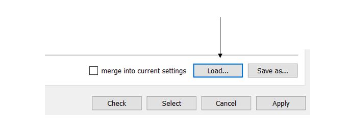
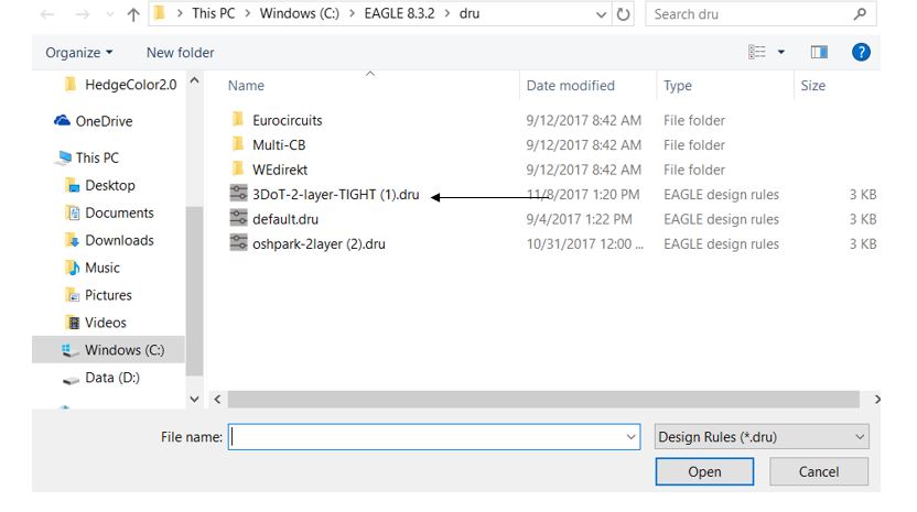
DRC checks are vital to completing a PCB layout. The DRC check used is the custom one made by Professor Hill. This DRC check is given below and should be the only one used because every fab house should be able to use this one. To use this DRC it will need to be downloaded and saved into the DRU files within the Eagle program. To perform a check click on the DRC check at the bottom of the tool bar. The user will then click on load and the correct DRC check. The user will then press the check button. This will generate an error report will have all of the errors of the PCB. The errors will need to be cleared for ordering of the board. It is also important to remember to turn on all layers before running the check.


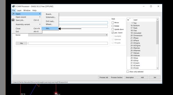
The last thing that is needed to create gerber files. To create gerber files you first go to the fab house that you plan on ordering from and seeing if they have the job files pre-made for you. OSH park already has these made for you and are easily downloadable. These job files once downloaded will need to be saved into eagle and specifically into the cam folder. Once the job has been saved it is time to generate the files. To generate the files go to file and then cam processor.  Then go to file in the cam processor window and then open and then job. Click on the correct job and then make sure the files are being saved into the right area. To conclude the making of the Gerber files click on process job.  If the cam files are unavailable from the fab house you wish to use then the cam files must be created in accordance with fabrication houses rules. To create these jobs one must click on the layer needed along with the names and file type. This concludes with pressing add and must be done for each layer.

Quiz 

EagleCad Training Part 1

EagleCad Training Part 2

Extra Training Material Provided by Eagle on YouTube

DRC Checks 


Generic Color Sensor Hedge follower PCB Layout

Written by Charles Banuelos


The PCB design below is for a generic hedge following shield. The PCB is a work in progress with the finalizing of the dimension dependent upon the testing of the color sensors. The LEDs chosen are significantly larger than the previous design and this is due to availability.


Update 11/30/2017

The PCB design was finalized and sent to OSH Park to be fabricated. The color sensors are placed 5.48 mm away from the edge of the board. The LEDs are placed 5.64 mm horizontally away from the color sensor towards the center of the board. The LEDs were changed due to availability as well as the issues with size. The orginal LED was too large and suitable replacement with similar specs was found. The final board dimensions are 10.87 mm wide by 55 mm long. The color sensors are placed 40.41 mm apart. The final draft of the PCB has the caster wheel cut out for 3DoT chassis as well.  The boards were received on 11/21/2017 and are currently being assembled.

Board 

schematics 

Parts List

Update 12/12/2017

This design was able to work for only one of the color sensors on one of the boards. The other color sensor was intermittent. This lead me to believe that the problem is in the soldering. The fabrication portion of this designed was plagued with many problems. The color sensor pads themselves are extremely small so when placed on the solder paste by hand the sensor would move and create bridges. The only way to mitigate this is to use the pick and place machine to ensure proper placement. The another issue found was that when a board was trying to be fixed with a heat gun the parts would burn before the solder would melt. This to could also be fixed by using the pick and place to ensure proper placement the first time. The last issue was with the stencil. The stencil would get clogged on the color sensor holes due to that fact they were very small. The only option to mitigate this is clean the stencil thoroughly after each use as well as use flux to ensure solder is in the right place.

Pete-Bot – Measuring Power Consumption

Written by Melwin Pakpahan (Mission, System, Test)

Description:

The power consumption of the 3DoT board will be measured as follows. A RCR123A battery will be connected in series with a test resistor and the 3DoT board. Two versions of the 3DoT board will be tested and compared. The test resistor is chosen to be 1 ohm, and the current draw is to be determined. When the power source is switched on, the voltage across the resistor is used to calculate the current going through the circuit using Ohm’s law.

Equation 1 – Ohm’s Law

Equation 2 – Variation of Ohm’s Law


Considerations

  • The battery is fully charged before any test is conducted.
  • A test code (“Motor_Operation_Test”) has been verified and uploaded to the 3DoT Board.
  • The motors continulously run during the test.

Cases

There are three cases of testing for the power consumption.

  1. Case One – Testing power consumption with no motors
  2. Case Two – Testing power consumption with one motor running
  3. Case Three – Testing power consumption with two motors running

Case One

Figure One  shows the circuit diagram for this first test:

Figure One – Circuit diagram for testing power consumption (general)

Case Two

A GM6 motor is connected and running as shown in Figure Two.

Figure Two – Circuit diagram for testing power consumption with one GM6 motor attached

Case Three

Two GM6 motors are connected and running as shown in Figure Three.

Figure Three  – Circuit diagram for testing power consumption with two GM6 motors attached

Constraint

Up until this point, Bluetooth communication has not been established yet. The procedures above will be repeated once communication is established.

Results

Figure Four shows a measurement of the resistor. Although, the specified value is 1 ohm, the actual value is 1.1 ohm. This measured value is desired since it provides a more accurate measurement of the current values. Figure Five shows the test run of the 3DoT board Rev 4.46 without actuators and without Bluetooth pairing. Table 1 shows the results of each test case.

Figure Four

Figure Five

Table of Results

Table One – Table summarizing results

References:

[1] Featured Image

Robot Avoidance Pseudocode

Written  by Elizabeth Nguyen (Project Manager)

Description: (updated on 11/19/17)

The robot avoidance code is a program that will allow robots to avoid each other under various cases after a robot detects another. There currently two parts: (1) Robot Detection (written by John Campo) and (2) Robot Avoidance. The psuedocode outlines a potential algorithm that can be implemented for the Robot Avoidance code.

Currently, this task is linked to Rules of the Maze.

Constraints

Due to the complexity of this algorithm, the psuedocode only assumes that two robots may collide with each other. Later on, it can be built upon in the case that three robots may collide with each other or even four.

Because of this constraint and based on the Rules of the Maze, it can be assumed that North- and East-facing robots will be not need to stray off their paths when “colliding” with a robot. South- and West-facing robots however will have to carry the burden to move away to allow the respective North- and East-facing robot to continue forward.

Also, regardless of direction, any robot located in an intersection will automatically carry the burden of moving away.

Pseudocode

Avoidance
   Identify direction
   Find out which room robot is in (Subroutine - WhichRoom)
   Get location from WhichRoom
   If the robot is in an intersection
      Save current location (this location can be passed to another subroutine where it can return to its original path)
      Move away (Subroutine - MoveAway)
      Return to its original path
      Continue the maze path
   Else (this is where direction will matter)
      If the robot is facing North OR East
         Check if a robot is in front of it (Subroutine - CheckAgain)
         Wait for 30 seconds (to ensure that the robot facing South moves away)
         Continue the maze path
      If the robot is facing South OR West
         CheckAgain
         Save current location (this location can be passed to another subroutine where it can return to its original path)
         Move away by backing into the nearest corner or intersection
         Return to its original path
         Continue the maze path
         
WhichRoom
   Determine location
   Return location to Avoidance subroutine

MoveAway
   Determine path to take
   Move backwards
   CheckAgain
   Return to Avoidance subroutine

CheckAgain
   Run Robot Detection Code
   If robot is detected
      Return to Avoidance subroutine
   Else
      Resume original path

Other Notes

Despite the current pseudocode possessing the parts of if-else statements, I believe it would be better to implement a finite state machine for avoidance. There also could be complications with determining how a robot can return to its original path after moving away. Interrupts may need to be utilized since there are many moments where a robot may not need to complete the avoidance subroutine.

Generic Color Sensor Schematic

Written by Charles Banuelos  MFG DM-updated 11/29/2017

The schematic below is for a hedge following shield that will connect directly to the 3DoT board. The hedge following shield will connect to the 3DoT board using the same 6 pin header that is used for the 3DoT IR shield. The design follows Thomas Forman’s designs from EE444. The color sensor being used is the BH1745NUC-E2CT-ND color sensor because this color sensor allows for two different I2C addresses to be used.  The hardware is designed to have the I2C addresses (0x038) and (0x39) in HEX. The LEDs chosen were chosen due to the fact that they were able to fulfill the specs needed such as light transmission, package size and current. The LEDs are used to light up the areas for the color sensors to detect the hedges. The mosfet in the schematics is used to control the LEDs which are protected by resistors. There are protection 10k resistors placed at the address pins to ensure protection of the color sensor.

Update 12/7/2017

The schematics below do not contain any form of reverse polarity protection. It should be stated then that when inserting the PCB in the 3DoT header that the orientation should be carefully monitored as to not accidentally flip power and ground. This could cause catastrophic damage to the circuit. It should also be noted that future color sensors should include a diode on the power line right after the header to protect from this. This design chose not to go with this at the time due dimension requirements of the PCB.


Goliath Fall 2017 – Gyro Test & Power Usage

The measured results are at the board level of the required voltage and current draw of the Gyro sensor. The voltage was able to measure with a simple multimeter but the current draw was in the single digit milliamps requiring us to use a more precise multimeter. We supplementally added a demo of how the […]

Pete-Bot Custom Command and Telemetry

Written by Elizabeth Nguyen (Project Manager)

Description:

A short list of custom commands and custom telemetry are defined in preparation for the EE 400D Fall 2017 Mission.

Custom Commands

  • Adjustable Speed Commands – Allows the robot to run at a specific set speed
    • Option for slowest speed
    • Option for medium speed
    • Option for fastest speed
    • On/Off for adjustable speed
  • Emergency On/Off Command – in the case that the robot is incapable of operating in Phase 2b
    • This is to avoid damage to the robot and other robots
    • Avoids the need for anyone to step into the maze and pick up the robot to disable it

Custom Telemetry

  • Display of Phase the robot is operating in
  • Robot detected
    • State that the robot is in during robot avoidance