Wheel Forces Calculations

By Anthony Dunigan

Back of the envelope calculations for wheels and electronic slip differential.

Table of Contents

Requirements

Level 2 Requirements

In order for the project to move forward in our Level 2 requirements numbers 8 and 9. We need to gather calculations based on our 6 in (0.0762m)  wheel diamater.

Constants and Variables

r = radius (m), m = mass (kg), g = acceleration of gravity (m/s2), u = dynamic friction coefficient, uo = static coefficient, F = normal force(N), Fpw = normal force per wheel(N), FNet = net force or tangential force(N), Fstatic = static friction force(N), Fdynamic = dynamic friction force or when the wheel slips(N), T = torque(N*m), M = motor torque(N*m), Ff = friction force(N), I = current (Amps), V = voltage (Volts), Pout = Output power of motor (W), Pin = input power of motor;

Calculations

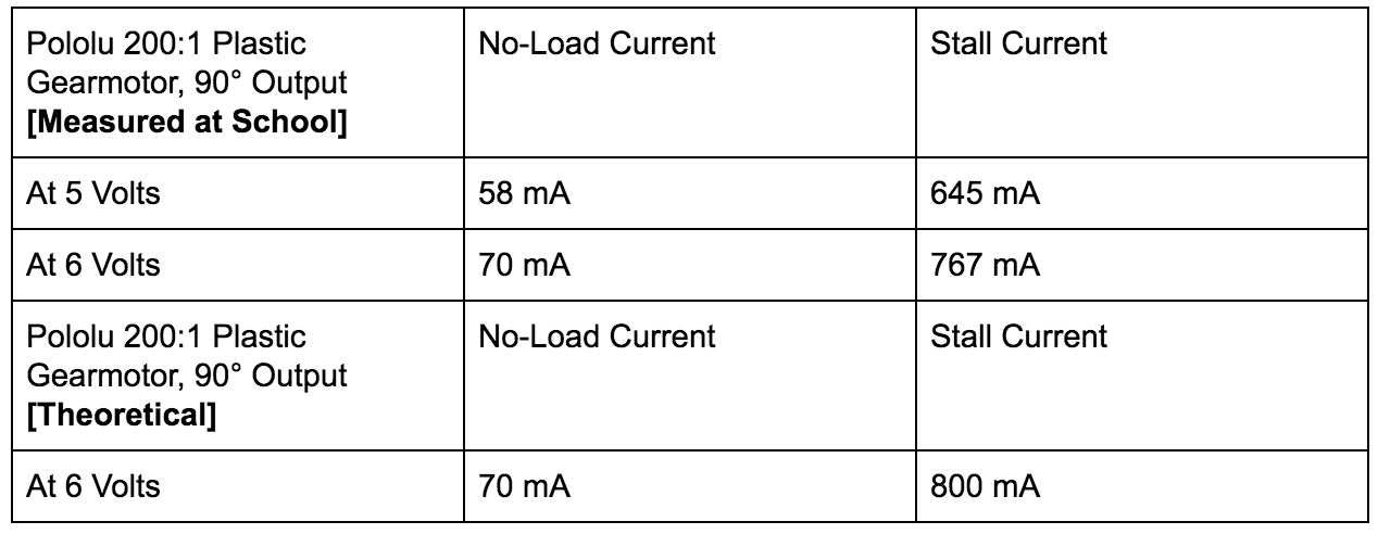
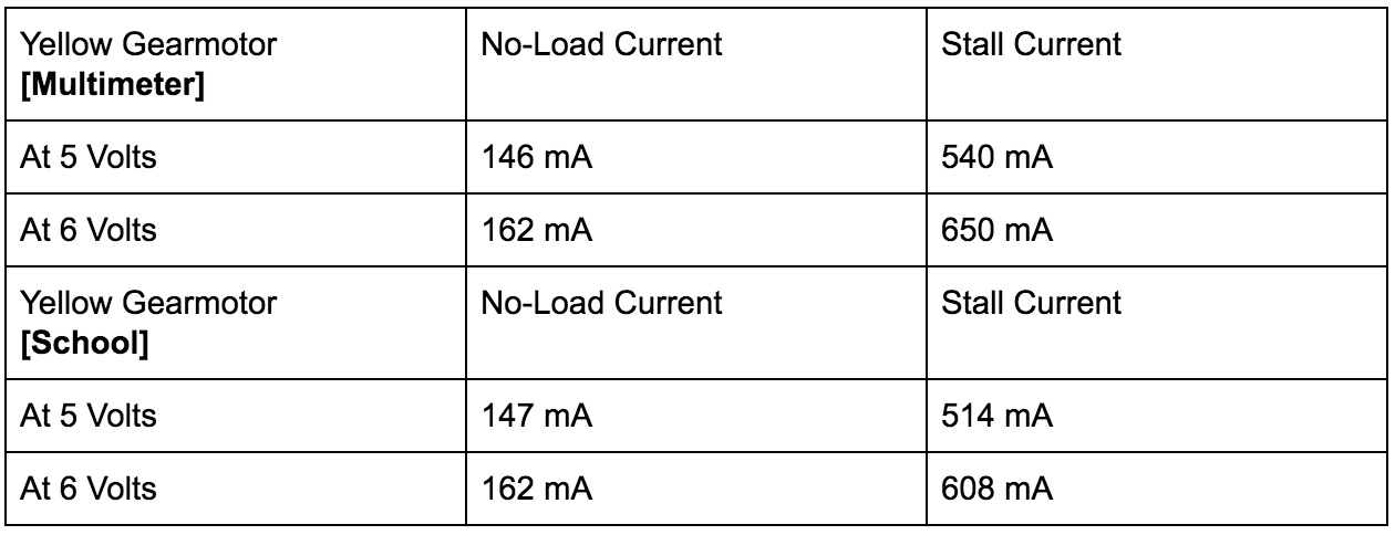
m = 22kg; g = 9.8 m/s2 ; u = 0.725 (rubber on concrete); uo = 1 to 4 or 2 (rubber on concrete); M = 0.339 N*m, I = 1.96 A, Pout = 9.3 W ,  at max efficiency; M = 1.13 when stalled.

F = m*g = 22kg *9.8 m/s2 = 215.6 Newtons (N), Fpw = F/6 = 35.93 N;

For the wheels to be balanced, static friction force must fulfill this inequations:

Fstatic  ≤ uo * Fpw =  (2) *35.933 N = 71.866 N;

If the static friction is unable to balance the system, then the static friction becomes dynamic friction and that’s when the wheel slips. The dynamic friction equation is:


Fdynamic  = u * Fpw = 0.725 * 35.933 = 26.05 N;

For the wheel to avoid any slip, the friction force which is dependent upon the motor torque (M) should satisfy the equation below:


Ff = M/R  ≤ uo * Fpw

Ff = 0.339 (N*m)/0.0762(m) = 4.45 N


So the  force acting on the wheels must not be greater or equal to the friction force of the motor.


Sources

http://e-collection.library.ethz.ch/eserv/eth:8200/eth-8200-01.pdf

http://hypertextbook.com/facts/2006/MatthewMichaels.shtml

http://simplemotor.com/calculations/

http://www.ebay.com/itm/24V-50rpm-Metal-Gear-DC-Geared-Motor-Reduction-Turbo-Worm-Gear-Motor-/321731427255

http://www.tsinymotor.com/cn/Products/wolunjiansudianji/2014/0619/118.html


Solar Current Sensor Experiment

(Written By: Edgardo Villalobos – Manufacturing/Solar Panel)

Using INA3221 current sensor breakout boards to measure current and voltage of a battery. INA3221 current sensors will be implemented in project to isolate voltage of each solar cells.

Table of Contents

Overview

This project requires current sensors in order to measure the current running through the solar cells. We are having 36 solar cells on the solar panel. We are using 12 INA3221 current sensor breakout boards to do this because they each contain 3-channels, support high-side current and bus voltage monitors with an I2C interface. These sensors are able to connect to the Arduino we will be using.


Circuit with Solar Cell

In the photo below, there is only one channel being used. The voltage is only measured because to measure the current, the circuit requires a load.

Arduino Code

The Arduino code for the current sensors is shown below for one channel. It defines the channels and names, sets all values to zero, reads the input values, and finally gives out the outputs for each of the channels being used.

Circuit with Battery

For practice, a battery and a resistor were used to find the voltage and current. The battery is the voltage source and the resistor acts as the load. The current sensor was able to record both current and voltage.

Pick and Place – Camera Test

By: Kevin Ruelas (Electronics)

Using the interface definitions defined in the camera document. I was able to test the camera to make sure it worked and was taking a photo correctly. The microSD board was a big part of this test as it was required to test the image before figuring out how to send it to Processing and if it was receiving the correct data. In terms of edge detection, I used an open source library called OpenCV. Upon looking at all their libraries I found the Canny edge detection to be the best for defining an edge. The photo is sent 64 bytes at a time and it may take up to 10 seconds for it to completely transfer the photo. From here, calibration code can be written to analyze the photo taken pixel by pixel and reference it to a calibrated photo in order to determine how much the X and Y axis needs to move so it can be at the origin.


Pick and Place – Z-Axis and Nozzle Test

By: Tiler Jones (Manufacturing) and Chastin Realubit (MST)

Z-Axis Motor: We did an experiment to see the load that the Z-Axis can handle and we found that it will still carry up to 2000 g. This experiment was done so that we can see if the motor can still move up and down even with more load. This was needed because we are adding a camera on the Z-Axis and we needed the system to still function with extra weight.

As seen on the pictures below, the Nozzle was completely removed due to its instability, the rods were replaced, and wires routed differently to reconnect and replace the nozzle to be stable so it does not move while the Pick and Place is running.


Spring 2017 Velociraptor: First SolidWorks Model

Authors

By: Andrea Lamore (Manufacturing)
Approved By: Jesus Enriquez (Project Manager)

Table of Contents

Introduction

During the early stages of the design process, leading up to PDR, the Velociraptor’s frame was similar to what was presented at CDR but had a few distinct differences in terms of specific part modification and part sizes. The purpose of this post is to present one of the first iterative designs for the Spring 2017 Velociraptor.

3D Modeling on SolidWorks

When first designing the hardware model for the Velociraptor, a design change was made so the Velociraptor could be made to walk with 2 DC motors. The Theo Jansen Linkage allows for walking with continuous rotation around a jingle joint, making it an ideal choice for the Velociraptor leg design.

The Velociraptor requires a turning mechanism. This could be done most obviously by having one leg take steps while pivoting around the other leg (much like how an RC car turns), or my adding an axis of rotation around one of the joints in the leg (either the hip or the ankle in our cases). Two universal joints at the hip was chosen to provide rotation at the top of the leg mechanism. This allows the continuos rotation of the leg  while the hip is at an angle.


The DC motor will be placed on the outside of the leg as to help with balance of the robot by moving mass away from the center axis so that shifting the center of mass (done by shifting the head and the tail) may be accomplished more easily. This also allows the motors to stay in parallel with the leg when the hip rotates.

When the velociraptor turns, the center of mass will move away from over the fulcrum point, for that reason two servos will control the head and tail independently. This was decided so that when the velociraptor turns, the head can be adjusted separate from the tail so that the center of mass stays over the fulcrum pint (over the standing foot). The following figure demonstrated how the center of mass changes with rotation of the hip.

Conclusion

As the iterative design process was pushed forward, through prototyping and trial & error, it led to further design changes leading up to our CDR design model. Realizing as oppose to modeling on SolidWorks is much more difficult and that was discovered through experience in assembly the physically manufactured parts for the Velociraptor.

Pick and Place – Solenoid Valve Design and Control

By: Tyler Jones (Manufacturing) and Kevin Ruelas (Electronics)

The above Figure 1 and Figure 2 schematics show the solenoid circuit simulated in LTSpice. The circuit on the left shows that when the arduino pin is set to high the circuit turns on allowing the current to flow through drain and source to the solenoid valve. The circuit on the right shows that when the arduino is set to low, there is no current flowing through the drain and source to the solenoid.

This creates an electronically controlled switch, and can be programmed to turn the pump on when picking a part, and off when placing a part. This is vital to the pick and place control system because it needs to be able to switch on using power from the Me Adapter board of +5V, to control a larger voltage of +11.7V from the Me Uno header pins. The IRF 530 MOSFET switches the gate voltage of +4.7V to the source drain voltage of +11.7V This voltage can is now large enough to drive a current to the solenoid and turn it on and off. The +4.7V control voltage from the arduino is programmed to correspond to the following values.

CODE SENT $9 (GCODE) $10 (GCODE)
ARDUINO PIN +4.7V (HIGH) +0V (LOW)
IRF 530 MOSFET ON OFF
SOLENOID ON OFF
SUCTION PUMP ON OFF
ACTION PICK PLACE

The solenoid was tested using an ammeter in series with the Drain of the MOSFET and wire of the solenoid. The current draw shown in Figure 3 through the MOSFET into the load was about 410mA. The turn on current needed to excite the coil in the solenoid was found to be about 310mA. This means that the solenoids resistance value can be modeled most accurately as an inductive coil load in series with a resistive load. The total resistance of the solenoid based on current draw was an operating range of about 24-35 ohms. The circuit works as designed and tested.

The tested circuit shown above was translated into a custom soldered PCB, in order to have the wires and components secured to a fixed location within the electronics housing. The PCB board will be mounted on standoffs inside the electronics housing.

Spring 2017 Velociraptor: DC Motor Selection

Authors

By: Mohammar Mairena (Electronics & Control)
Approved By: Jesus Enriquez (Project Manager)

Table of Contents

Introduction

Through research on DC Motors, I came across gear motors. Gear motors add mechanical gears (gearbox) to reduce speed/increase torque and vice-versa. The increase in torque is inversely proportional to the reduction in speed. Each gearmotor has a different gear ratio that alters the torque/speed calculations. Through the E&C division manager and Professor Hill, I borrowed what were said to be two GM 7’s and a GM17.

Requirement:
L2EC – 4: The velociraptor shall use DC motor(s) to drive the legs of the Velociraptor

Selecting the DC Motors

After testing what was supposed to be two GM 7’s, I realized the current values did not match up to those on the GM 7 datasheet. Upon further research, one of the GM 7’s turned out to be the pololu 200:1 plastic gearmotor with a 90° Output. The other motor was also not a GM 7 as it drew much more current than a GM 7. For both motors, I measured two things: stall current and the free running current at no-load. The stall current is the current at which the shaft of the motor is no longer rotating (under max torque conditions).
Comparing both motors, it is clear that the Pololu is much more ideal for our robot due to the low current draw it will have in comparison to the other yellow motor. In addition, it is important to note that the current draw from the Servo motors has not been taken into account. The Pololu gear motor is a great alternative to the GM 7 for 2 reasons: low current draw and high torque output.

Table 1: Pololu 200 Results

Table 2: Yellow Gear Motor Results

Resources

1) https://www.pololu.com/product/1120/specs
2) http://www.robotshop.com/en/solarbotics-gm7-gear-motor-7.html


Spring 2017 Velociraptor: Fritzing Diagram

Authors

By: Mohammar Mairena (Electronics & Control Engineer)
Approved By: Jesus Enriquez (Project Manager)

Table of Contents

Introduction

Before one can create a custom printed circuit board (PCB), one has to create a Fritzing diagram. A Fritzing diagram is a virtual electronic circuit that is modeled after a circuit tested on the breadboard. Fritzing is used to provide the layout of the breadboard given the tools needed for a future PCB design.

Fritzing Diagram

The diagram shown is the Fritzing diagram our group used for the Preliminary Design Review (PDR). The diagram is a very rough idea of the parts we are using for the final schematic. This diagram is meant to provide a general idea of the parts needed for the final PCB design. Each part shown serves a purpose.

The breadboard consists of the 3Dot board, three servo motors, two DC motors, an external battery, an A/D converter with rotary/shaft encoders, an additional low-dropout voltage regulator for the extra servo motor and a GPIO expander. Two DC motors are used to control the legs of the raptor, one servo motor to control the head and another to control the tail. The extra servo motor will be used to control the turning motion of the Velociraptor. Since the 3Dot board is only capable of utilizing two servo motors and two DC motors, a PWM expander is necessary for our additional servo motor. The PWM/Servo driver is not shown and should replace the GPIO expander in the design. The PWM/ Servo driver with i2C interface has the capacity to add extra servos through two pins, SDA & SCL (Data and Clock).


Note: The 3Dot board was taken from Fall 2016 Velociraptor’s fritzing diagram.

Resources

  1. http://web.csulb.edu/~hill/ee400d/Technical%20Training%20Series/07%20FritzingDocumentation.pdf        
  2. https://www.arxterra.com/fall-2016-velociraptor-w-fritzing-diagram/ 

Spring 2017 Velociraptor: RGB Color Sensor

Authors

By: Mohammar Mairena
Approved By: Jesus Enriquez

Table of Contents

Introduction

The Velociraptor will compete in a game similar to Pacman. One of the requirements is that the Velociraptor shall attempt to collect as many red dots as possible while navigating the maze utilizing either a static or dynamic walk. As a result, we will be using an IR sensor to detect the dots in the maze. My choice for the color sensor is the Sparkfun RGB Color Sensor. The reason I chose this specific sensor (APDS-9960) is because of the detection range and the operating voltage at 3.3 volts. In comparison to other sensors, this one has a lengthy detection range of 4-8 inches.

Analysis

The SparkFun sensor includes examples of Arduino library code for color sensing and proximity detection. I tested the color sensor and proximity sensor with the library code. After hooking up the sensor to the breadboard and uploading the code, I placed different colors up to the sensor. I had a hard time distinguishing colors using the serial monitor on the Arduino interface.

Conclusion

In retrospect, the SparkFun RGB Color Sensor is an ideal infrared sensor for the Pacman game however, detecting the different colors (red, blue, green) proved to be very difficult. Another disadvantage of this sensor is that it is very miniscule and would only detect the red dots if they were large in size. Completing this experiment helped me realize how minute the sensor was and how important it is going to be to correctly place the sensor on the robot.

Resources

  1. https://www.sparkfun.com/products/12787

Spring 2017 Velociraptor: SolidWorks Hardware Design Model

Authors

By: Andrea Lamore (Manufacturing)
Approved By: Jesus Enriquez (Project Manager)

Table of Contents

Introduction

Throughout the engineering design process, the SolidWorks model for the Velociraptor went through a series of changes as our team went through trial and error with the different components for the robot. This post includes some of the thinking that went behind the hardware design of the robot.

Hardware Design

Servo Holder

Previously we planned on 3D printing and ordering all the parts necessary to build out first prototype. I modified and added a few parts to the velociraptor skeleton in anticipation of some problems that might occur during the build phase.

Mounts for the server were added to the bottom of the velociraptor for hip movement. Two or one servos could be placed here to accomplish hip rotation.

Head & Tail

Horizontal ball bearing will be used to facilitate rotation of the head and tail and the hip. The weight of the velociraptor is being supported by the legs, meaning that the body will resting on the hip mechanism which is attach to the legs – bearing will be added along the shaft of the hip that attaches to the leg. In order for the horizontal bearings to turn properly the outer and the inner radius of the bearing must not both be resting on the same surface. Circular extrusions for the parts resting on the bearing will be used to allow for proper slipping. The same horizontal bearing mechanism will be used to facilitate head and tail rotation.

Leg Mechanism

An issue with the Theo Jansen mechanism is the inability to keep the foot parallel to the floor is. Instead the foot moves in parallel with the legs circular motion. This means that that the whole body will shift back and forward with the foot motion when the velociraptor takes steps. With our first prototype, where we intended to use servos, a mechanical mechanism to keep the foot parallel to the floor could easily be incorporated into our design. A rounded out sole and a pair of springs attached to a pivoting joint at the angle was incorporated into the design in order to keep the foot parallel while  it is carrying the weight of the velociraptor(when it is the supporting foot being used to stand). The rubber sole will give the velociraptor height in order to prevent the toe from hitting the floor on steps and to keep the foot from slipping.


Conclusion

After going through the design process, there was still consistent changes throughout the semester in terms of Hardware design as our team consistently went through prototyping. As a result, we ended up deciding to do most of the manufacturing through laser cutting instead of 3D printing according to our original plan.