Spring 2017 End of Semester Game “Pacman”

By: Alexander Clavel

Apporved By: Game Committee

Table of Contents

Game Committee Members:

Amber Scardina – TRC President

Alexander Clavel – BiPed Project Manager

Nicholas Jacobs – Spiderbot Project Manager

Jesus Enriquez – Velociraptor Project Manager

Overview:

The BiPed and Velociraptor will participate in a game of PacMan. Both robots will start on opposite ends of a maze with the BiPed initially acting as PacMan and trying to avoid the other robot. The BiPed and the Velociraptor will attempt to collect as many “dots” or points as possible within the allotted time limit. The Velociraptor will initially act as the “ghost” and try to catch Pacman before the end of the game while also collecting points. The game will start once the Spiderbot has reached its position and begins video feed. The game will last a maximum of 30 minutes.

Rules:

–   Spiderbot will walk into the maze and then place itself above the maze for video set up

   Biped will start off as “Pacman” while the velociraptor starts as the “ghost”

  Both robots will start in different ends of the maze

   There will be red dots on the ground which will be “counted” and displayed on both robots as they pass over a dot.

–   If the Velociraptor reaches and “eats” the BiPed before the 30 minutes then the raptor wins

   If the Velociraptor does not “eat” the BiPed then the winner will be determined by who has the most dots counted.

   There will be special grid squares to make the velociraptor vulnerable to being “eaten” and will reverse the rolls

–   If the BiPed can reach the velociraptor within the time limit then the velociraptor loses.

   Live aerial video feed will be provided by the Spiderbot

   Time limit of 30 minutes OR when the ghost catches Pacman OR when one group reaches 5 dots first.

–   If a robot falls over, that will count as a deducted point and they will start again at their starting area.

–   Points will be deducted at the end of the game by subtracting the endgame amount from the number of times the robot has fallen

View and Control:

      BiPed and Velociraptor will view the gaming field through video feed provided by the Spiderbot

      Both Robots will be controlled through the arxterra control panel
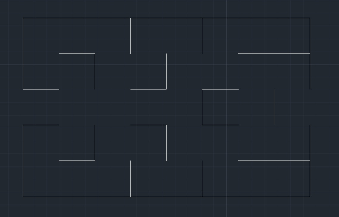
Terrain:

      35 in x 56 in area

–       Flat paper taped across the tiled floor of the classroom

      No physical walls

–       The Maze will be printed on paper

      7 inch width for walkways for the robots

      Roof with steel area for magnet and supports made of wood for the spiderbot height TBD


Game map to be updated , Dots to be added***

SpiderBot and Velociraptor Starting Point – Left Opening

BiPed Starting Point – Right Opening

Spring 2017 BiPed – Servo Ankle Stress Experiment

By: Abraham Falcon (Electronics and Control)

Approved by: Alexander Clavel (Project Manager)

Table of Contents

Introduction:

Electronics and Control engineer job is to do an experiment on the servo motor to see if it can the handle the weight needed to perform the funtion of turning at the ankle. The following experiment is to know if the chosen servo motor can handle the Biped’s weight. The stress weight of the Biped was chosen to be at 500 grams as to be the maximum weight, but our actual weight should be lower than this. The experiment is also to see if the power consumption of the servo will exceed our maximum of 500 mA.

Experiment:

Table of results:

Servo Motor Servo Location Stress Weight Operating Voltage (Volts) Stress Current

(Amps)

HXT900 Micro Servo Ankles 500 grams 3.3 volts 270 mA

This experiment was done by hooking up the servo motor to the arduino and the digital multimeter in series. The weight of 500 grams was attached to a servo plastic gear with a radius of 1cm.


Here is an example of the servo connection without the weight and you can see that with no load the servo runs at the highest 71.961 ma.

The setup from above picture was used but added the weight of 500 grams. To simulate the weight of the ankle from Biped weight the servo was put upside down and observed if the full rotation of the gear on the servo with the weight performs well. By observing the weight on this servo, it can handle the stress weight of the biped and the current was around 270 mA.

Conclusion:

The experiment was preformed and showed that this HXT900 Micro Servo will make Biped be able to turn on the ankles and the current shows that the power consumption is under 500 mA. This experiment concluded that this servo will be effective for the ankles to turn. In the references section shows a video of the servo torque test of this type of servo chosen and this was a guide to perform this experiment.

Referrences:

  1. https://www.youtube.com/watch?v=dCgiE0xpToI&index=11&list=FLoSP5pt7W0bsWc1xuJASmww&t=168s

Encapsulation Trade Off Study

By Edgardo Villalobos

Study on types of solar cell encapsulation.

Table of Contents


PLEXIGLASS

Plexiglass provides a lightweight, about 3 lbs per 8 sq. ft. with a 0.065 thickness, anti-reflective surface and is classified as a scratch resistant surface. Although plexiglass is virtually impossible to break and scratch resistant, it can scratch much easier than glass. If this material is used to encapsulate solar cells, we’d be able to acquire it from Home Depot or other similar store. This glass would then be used to cover the entire panel. To get the right shape out of the glass, we could use a dremel grinder to cut to size. The size of the glass would be the same size as the panels, which still need to be measured. The downside to using plexiglass is that each solar cell needs to be sandwiched using other materials, such as resin, which costs more.


Source:

[1]Plexiglass

http://www.plexiglas.com/export/sites/plexiglas/.content/medias/downloads/sheet-docs/plexiglas-optical-and-transmission-characteristics.pdf

[2]Materials

http://sinovoltaics.com/learning-center/materials/ethylene-vinyl-acetate-eva-film-composition-and-application/

[3]Materials

http://www.dunmore.com/products/solar-back-sheet.html


EPOXY COVERED SOLAR CELLS

Solar cells could be bought already encapsulated with a UV resistant epoxy and are usually meant to charge phones. Each cell is independently encapsulated making it easier to remove and add new cells. These cells are also polarity based, which could require wires instead of tabbing wires, also making it easier to switch cells. Using these cells would cost about the same as buying all the materials, using the plexiglass sandwich method.


Source:

[1]Array

http://www.samlexsolar.com/learning-center/solar-cell-module-array.aspx

Chassis Fritzing Diagram

By Renpeng Zhang

Fritzing Diagram for Chassis.

Diagram

Description

Based on the interface definition, I created the fritzing diagram for the chassis part of the pathfinder. It consists of the Arduino Leonardo with two HC-SR04 ultrasonic sensors. It has the HC-05 bluetooth module connected to the Arduino through the TX and RX pins for the communication through a phone using the Arxterra app. Two servos is connected to the Arduino for the control of the pan and tilt of the rover. Two PCA9685 I2C expander were used for extra digital PWM and analog input pins. The VNH2SP30 motor driver is connected to the I2C expander and it’s used to control the speed of the motors. The built in current sensor of the motor driver is connected to the analog input of the Arduino for the monitoring of the current going through each motor. Battery was connected to power the motor drivers.

Spring 2017 BiPed – PCB Schematic

By: Abraham Falcon (Electronics and Control)

Approved by: Alexander Clavel (Project Manager)

Table of Contents

Introduction:

Electronics and Control engineer is to create a custom PCB and to layout the components to be used. The PCB components are a PCA9685 PWM expander, pin headers for the LEDs and a pin header for the color sensor.


Eagle Cad Schematic:

The Biped PCB schematic below shows what the main components are to be use with the 3Dot board, which is the color sensor and a LED counter.

This PCB schematic is the third version and to be used on the Biped mainly for the game. Previous PCB schematics had two extra servos from the main design of the biped. As we moved forward with the design of the Biped, the customer stated that the power was the be supplied without an external battery. Power should soley be provided by the 3Dot board battery. The servos were eliminated to reduce the power consumption and therefore the PCB schematic above is the final version to be used with the 3Dot Board.

The PCB needs to communicate with the 3Dot board and the PCA9685 PWM expander will handle this. The PCA9685 PWM expander handles multiple PWM pins as the 3Dot board does not provide. Connecting multiple devices to the PCA9685 PWM expander will communicate to the 3Dot board through the I2C bus.

There will be two LEDs for the Biped to represent the eyes that are colored red and signify that the robot is indeed on. The other LED which is green is to represent a counter for collecting colored dots from the “end of semester” Pacman Game. All the LEDs connect with a 1k Ω to PWM expander, which these resistors are to limit the amount of current going through the PWM expander for protection. The LEDs are not physically connected to PCB board therefore it will use pin headers so the LEDs can freely be placed anywhere around the Biped.

For the Biped to sense the color dots from the game it will be using a Adafruit RGB Color Sensor and this sensor will also not be physically connected. The colored dots are placed on the floor therefore the color sensor must be placed on the foot to sense the color dots. The pin headers have the connection needed to connect to the 3Dot board and be powered by it. The pin headers connect to the I2C bus from the 3Dot board, which are SDA and SCL. Also from the 3dot board the power and ground can be connected to the sensor provide from 3Dot board connection. The pin headers are placed so that the color sensor can freely be placed anywhere on the biped and for this design we chose it to be on the foot.

The other components on the PCB schematic were provide from the product website, where they also provided Eagle Cad files. All the components are surface-mount devices. These components were left alone as the product works with it.

Conclusion:

The completed PCB schematic is simple but pushed our design to have less power consumption and to participate in the “end of semester” Pacman Game. The completed PCB Schematic is sent to the manufacturing engineer to layout the PCB and to be completely assembled.

Referrences:

  1. http://www.mouser.com/ProductDetail/NXP- Semiconductors/PCA9685PW118/?qs=sGAEpiMZZMvKM5ialpXrmnWDpPMxsdrM
  1. http://www.mouser.com/ProductDetail/Broadcom-Avago/HLMP-3301/?qs=sGAEpiMZZMsx4%2fFVpd5sGeS9q14uN1KF
  1. http://www.mouser.com/ProductDetail/Broadcom-Avago/HLMP-3507/?qs=sGAEpiMZZMsx4%2fFVpd5sGbU8v9L8Znih
  1. https://www.adafruit.com/products/1334

Solar Cell Current Sensing

By Edgardo Villalobos

Custom PCB created by combining two INA3221 into one board.

Table of Contents


INA3221


Original Eagle CAD


Custom PCB with 2 INA3221


Three INA219 = One INA3221


Description

The INA3221 is a three-channel, high-side current and bus voltage monitor. It contains the setup of 3 INA219 single-channel, high-side current and bus voltage monitor.


Setup

The solar panel on the pathfinder rover contains 6 different panels with 6 solar cells on each panel that are setup in a certain way in series and parallel to get an output of 18 volts and 200 milliAmp from each of the panels to get a total of 18 volts and 1 amps. To test the current flowing through each of the 36 cells, we are going to use the INA3221 current sensor. As described in the INA3221 datasheet, this sensor senses current on buses that can vary from 0V to 26V. Because the INA3221 is three channels, it only measures the current running through 3 inputs, meaning we’ll need 2 per panel. The original Eagle CAD PCB layout was modified in order to get a total of six inputs that will match up perfectly with the 6 cells on each panel, meaning we will only need 6 boards as opposed to 12.

Since the these sensors can only have 4 addresses, I2C multiplexers are required.

Parameters


References

http://www.ti.com/product/INA3221/description

http://www.ti.com/lit/ds/symlink/ina3221.pdf

http://www.ti.com/lit/ds/symlink/ina219.pdf

http://www.switchdoc.com/wp-content/uploads/2015/04/INA3221BOB-042015-V1.0.pdf


Eagle CAD Files

https://drive.google.com/drive/folders/0B4jU8uMDmOoiU1dOM0tzSU1qeHM

  • Custom Eagle CAD Schematic: Current_Sensors.sch
  • Custom Eagle CAD PCB : Current_Sensors.brd
  • Original Eagle CAD Schematic : ina.sch
  • Original Eagle CAD PCB : ina.brd
  • INA3221 Eagle CAD Library : ina.lbr


Pick and Place – Updated Requirements and Mass Reports

By: Chastin Realubit (Missions Systems and Testing)

Level 2 Requirements:

  • L2-1: Attached compartments shall not interfere with the functionality of the machine.
    • L2-1a: Wires shall be shielded or incorporate heat shrinks in all areas of the pick and place machine.
    • L2-1b: The RJ-25 cables shall be able to reach every operable part of the aluminum picking surface, while maintaining a standard of bend radii of 2 inches to prevent fatigue while running.
    • L2-1c: All microcontrollers, shields, electronics, and precision sensitive running gear shall be isolated from vibrational or other outside disturbances.
    • L2-1d: Compartments to house, wires, electronics, pumps, tape, and accessories will not occupy more space than half a foldable table.
    • L2-1e: The legs of the machine will be raised so that the cabinet can be placed.
    • L2-1f: The cabinet shall be used to hide the hardware (i.e. vacuum, Arduino, etc).
    • L2-1g: The cabinet should be formed using vacuform to make the machine look neat and professional.
    • L2-1h: The legs of the machine will enclosed with a material that can reduce the vibration of the machine to make it more accurate.
  • L2-2: The camera of the pick and place shall be used to incorporate edge detection technology (used as an alignment camera, the same as the Madell Pick and Place).
    • L2-2a: Pick and place shall incorporate edge detection to determine origins
    • L2-2b: Pick and place will have dedicated Arduino for camera system
  • L2-3: The Pick and Place will include video tutorial, written manual, sample test files.
    • L2-3a: Pick and place shall have detailed instructions on how to operate the machine through the software
    • L2-3b: Pick and place will incorporate LCD to make machine more user-friendly (Display status, component being placed etc.)
    • L2-3c: The user will be able to interface with the machine, and control the machine with an emergency power button.
    • L2-3d: The user manual should include a video to guide users on how to use it. (The video will show step by step how the user will interface with the GUI, where to download all software, and how to turn gerber file into cnc file.)
    • L2-3e: The manual will include a troubleshooting section that will help users fix the machine in case hardware was accidentally disconnected.
  • L2-4: The case should enclose the machine, and hold its weight in a manner of minimal movement when carrying.
    • L2-4a: The pick and place should be remained locked and secure to it location of setup.
  • L2-5: The machine shall be faster than human production time of 4 Hours.
    • L2-5a: Pick and place will incorporate the addition of eight additional servos
    • L2-5b: All part tape shall be managed and hassle free throughout the entire operational procedure of the machine.
    • L2-5c: All parts needed to create a 3DoT board shall be able to be picked and placed within tolerances of + or – 0.2mm.

Mass Report

Vacuum System Components Preliminary Mass (g) Uncertainty (%) Margin (±g) Expected Mass (g) Actual Mass (g)
Stepper Motor (A-Axis) 245.00 5% 12.25 245.00 247
Stepper Motor (Z-Axis) 245.00 5% 12.25 245.00 246
Vacuum Nozzle 2 5% .1 2 TBA
Z-Axis Actuator 292.00 5% 14.6 300 244.12
Detection Camera 3 5% .15 3 TBA
Project Allocation Experiment: The Z-Axis motor can still function after attaching 2000g as a load.

The vacuum will still need to be experimented on to see how much load can be placed on it.

So our preliminary allocation is 2000g

Total Expected Mass 795 g
Total Margin 39.35 g
Total Actual Mass TBA
Contingency  1165.65 g


Experiment:

Z-Axis Motor: We did an experiment to see the load that the Z-Axis can handle and we found that it will still carry up to 2000 g. This experiment was done so that we can see if the motor can still move up and down even with more load. This was needed because we are adding a camera on the Z-Axis and we needed the system to still function with extra weight.

Next steps:

We will now need to test the suction of the pump to check if it can carry the ICs that the 3Dot will require of us.

Power Report

Components Expected Current Draw (A) Uncertainty (%) Margin (±A) Measured Current Draw(A)
Stepper Motor (X-Axis) 1.35 5% .0675
Stepper Motor (Y-Axis) 1.35 5% .0675
Stepper Motor (Z-Axis) 1.35 5% .0675
Stepper Motor (A-Axis) 1.35 5% .0675  
Detection Camera .75 5% .0375
Display Screen .75 5% .0375  
Servo fs90r (12) .3 .05 .015  
Project Allocation 6 A (Calculated knowing that we will be using two Arduinos with separate power supplies)
Total Expected Current 3.15 A (The motors and servos will not run simultaneously)
Total Margin .36 A
Contingency 2.49 A

Pick and Place – Servo Driver

By: Kevin Ruelas (Electronics)

The system block diagram presented in the PDR is undergoing changes, especially regarding the additional servos. The system block diagram that was made currently has two micro controllers connected via I2C. Both utilize the Me UNO shield and one port could generally house two servos.

Using a 12-bit PWM/Servo Driver we can hook up all twelve of our servos utilizing just one Ethernet port on the existing Me UNO shield. It would still require an RJ25 adapter in order to make all the right connections.

Figure 1. PWM Servo Driver via adafruit

Figure 2. Makeblock RJ25 Adapter via Makeblock

 A general Ethernet port for the Me UNO shield consists of two digital/analog pins, 5V, GND, SDA and SCL for I2C. For the driver, the 5V (Vcc), GND, SDA, and SCL pins will be used. The 5V (Vcc) from the Arduino is power for the driver, not the servos. So in order to make sure that there is enough power for the servos, an additional battery pack shown in Figure 3 will be required.

Figure 3. 4 AA Battery Pack via adafruit

Figure 4. Block Diagram for the servos

Using this driver would get rid of the Master-Slave micro controller combo and will also enable us to dedicate the second Arduino for an independent camera system. The main Arduino would house all the motors, limit switches, servos, solenoid valve, as well as the new LCD.

References

https://www.adafruit.com/product/815 (Servo Driver)

https://www.adafruit.com/products/830 (Battery Holder)

http://www.makeblock.com/me-rj25-adapter (RJ25 Adapter)

Pick and Place – Trade Off Study – Camera System

By: Kevin Ruelas (Electronics and Control)

Due to the use of a servo driver to control the existing and additional servos, a separate Arduino can be used to house an independent camera system. This Arduino will have its own code as well as utilize visual software for edge detection.


It was important to choose a camera that is lightweight, and small enough to be mountable on the current Z-Axis. The following are the cameras that I looked at that could possibly work.


  Price Size Weight Resolution Operating Voltage
Miniature TTL Serial JPEG Camera with NTSC Video 35.95 20mm x 28 mm 3g 640 x 480 3-5 V
TTL Serial JPEG Camera with NTSC Video 39.95 32 mm x 32 mm   640 x 480 5 V
Weatherproof TTL Serial JPEG Camera with NTSC video and IR LEDs 54.95 2 in x 2 in x 2.5 in 150g 640 x 480 5 V


The Miniature TTL Serial JPEG camera fits the needs of the project the best, as it is the smallest, lightweight and still maintains a decent resolution.


The Arduino UNO by itself does not have the capability for image processing so once the picture is taken, it will need to be stored externally and then sent back to the computer to a software called Processing.


https://processing.org/


Processing is an integrated development environment (IDE) written in Java. It is here where edge detection code will be written to detect the edge of the PCB, or whatever the camera is looking at. From there the coordinates of the edge will be extracted and fed back to Gremote.

Figure 1 – Miniature TTL Serial JPEG Camera with NTSC Video


Figure 2 – SD Card Breakout board


Figure 3 – Diagram


SD CARD PINS ARDUINO UNO PINS
CS (SS) Digital Pin 10
DI (MOSI) Digital Pin 11
DO (MISO) Digital Pin 12
CLK (SCK) Digital Pin 13
3V 3.3 V
GND GND


CAMERA PINS ARDUINO UNO PINS
5 V 5 V
GND GND
TX Digital Pin 1
RX Digital Pin 0


References


http://web.csulb.edu/~hill/ee400d/Project%20Folder/Camera/Camera%20Document.pdf


https://processing.org/


https://www.adafruit.com/products/1386


https://www.adafruit.com/products/254

Spring 2017 Velociraptor: Range of Motion Prototype

By: Andrea Lamore (Manufacturing)
Approved By: Jesus Enriquez (Project Manager)

Table of Contents

Introduction

The range of motion of the leg determines the type of step the robot will take. A static walk requires a different stride from a dynamic walk and it is important to pick the linkages in the leg according to the type of walk that the robot will be using. The robot is to fulfill the following requirement:

L1-7: The Velociraptor shall be able to perform a static walk


Prototype

The velociraptor we are building shall have a static walk which uses two DC motors, so the Theo Jansen linkage was chosen as the optimal leg design for the robot. The following is the 3D printed model of the Theo Jansen Linkage. Before choosing the Theo Jansen Linkage [1] a series of other leg designs were cutout from cardboard and pinned together at the joints to simulate range of motion on a 2D plane.

Figure 1: Theo-Jansen Leg Mechanism Prototype

Conclusion

The 3D printed model of the Theo Jansen Linkage was scaled up for this prototype just to get an early idea of whether or not to implement this idea into our design. This leg mechanism will be rotating upon a single axis of rotation using a DC motor to over all drive the load of the robot.

References

[1]: https://en.wikipedia.org/wiki/Jansen%27s_linkage