Spring 2017- Arxterra ArxRobot Camera Experiment

Table of Contents

By Nicholas Jacobs – PM

By Jefferson Fuentes – MST

Requirements:

Spring 2017 SpiderBot is required to provide live aerial video feed capable of covering the entire arena, as defined by end-of-semester-game, to other participating robots.  


Introduction:

The ArxRobot phone app works in conjunction with the Arxterra mission control panel.  The app utilizes the phone’s built-in camera, and transmits data wirelessly via internet connection to the control panel.  From the control panel the user is able to see what the phone sees.  For the specific purpose of the Spiderbot, it is required to provide a live video feed of the game arena to the other participating robots.  The camera test is used to determine the minimum distance the phone camera must be to provide coverage of the entire arena.

Procedure:

The camera test was conducted using the Arxterra control panel, the Arxrobot app, an android phone, a wall, a tape measure, and tape to mark off varying lengths along the wall.  The android phone used is a Huawei Nexus 6P.  On the wall, a square of known length and width is marked off, setting up a mock arena.  Once set up, the phone is incrementally set further away from wall, until the entire mock arena is encompassed on the ArxRobot and Arxterra Screen shown in figures below.

Phone Camera Specifications:

Model: Huawei Nexus 6P

Megapixels: 12.3
Pixel size: 1.55 μm pixels
Aperature size: F2.0
Hardware: IR laser-assisted autofocus
Video(max): 4K resolution
Flash: Broad-spectrum CRI-90 dual flash

Features: 240fps slow motion video capture

Results:

3×3 Square Arena

Fig 1. Arxterra Visualation(3×3)


Fig 2.  Arxrobot Visualization (3×3)


Fig 3.  Arxterra Visualization (5×5)


Fig 4. ArxRobot Visualization (5×5)


Tables

Arena(ft) Distance(in)
3×3 53
5×5 73


Conclusion:


The Nexus 6P, in conjunction with the ArxRobot app and Arxterra mission control panel are more than capable of delivering live video feed.  The field of view delivered is dependent on the distance the phone camera is from the arena, at least 53 inches for a 3×3 arena.  Looking at figures 1 and 2, an important observation can be concluded.  The onboard camera is not optimized for a square arena, instead a rectangular arena, would much more effectively use the camera’s full field of view. My recommendation would be to implement a 3’X5′ game arena, this will require less materials to construct a suitable anchor point and provide the best possible view of the arena for game participants. SpiderBot out….  


Resources:

  1. http://www.androidcentral.com/nexus-6p-specs
  2. http://www.gsmarena.com/huawei_nexus_6p-7588.php


Spring 2017-Arxterra Control Panel Update!!!!

Written By Jefferson Fuentes

Table of Contents

Introduction:

The Arxterra mission control panel is to work in conjunction with the Arxterra phone app, transmitting and receiving information to and from the robot.   It serves an extended/secondary means of control with more capability than the Arxterra app.  The control panels main purpose is to increase the capable range for controlling the robot, theoretically to anywhere in the world, as opposed to the limit of the Bluetooth range.  It is also capable of providing more telemetry to user than the app, i.e. video feed, pitch, roll, speed, robot location, and any other as needed information.  


Requirements:

The Spring ’17 SpiderBot is required utilize the Arxterra phone app to control the robot remotely via bluetooth.  SpiderBot is also required to provide aerial live video feed capable of covering the entire arena of the end-of-the-semester game to other participating robots.  The video feed will be accomplished by SpiderBot’s ability to hoist itself up in the air through use of a grappling system.


Set Up:

To utilize the Arxterra mission control panel a quick setup is required.  The following is a walkthrough of the process.  


Part 1:  Arxterra App Initialization

The first step is to attain permission from the administrator to access and download Arxterra app.  The Arxterra app uses a Bluetooth link to connect to SpiderBot to facilitate movement control. 

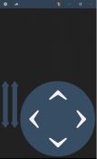
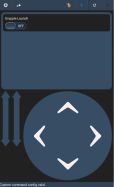
Fig 1. Arxterra App initial launch screen


On boot up, the Arxterra app begins in the remote control function(fig 1) by default.  This function allows us to control the robot with a phone via a Bluetooth connection.  To control the robot using the control panel, the next step is to switch over to community mode.  This can be achieved by pressing the function icon on the app (fig 2), which allows us to toggle between robot and community mode.   

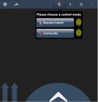
Fig 2. Toggle Function


Toggling community mode launches a sign in window (fig 3), with two required fields Robot name and Pilot name or names.  These two fields are used to define which robot is to be used, and who has access to controlling it through the Arxterra mission control panel.  Confirmation of success is given by a message at the bottom left corner of screen, “Live cast published” (fig 4)

At this point, all necessary steps have been achieved concerning the Arxterra app.  As an added method of determining whether the Arxterra app and arxterra control panel are working properly.  A simply check on the app will verify functionality.  Clicking the camera icon after the login procedure will display basic camera feed status as well as a display window showing what the phone is streaming(fig 5).


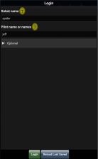
Fig 3.  Arxterra login window     Fig 4. Login Success


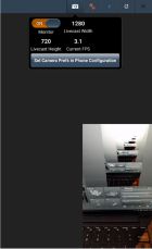
Fig 5. Connection Test


Part 2: Arxterra Mission Control Panel Initialization


Procedure:

Next is the Arxterra Mission Control Panel interface setup.  The control panel is used as an extended/secondary mode of control over the robot.  Its main function is an increased range for controlling the robot, as well as providing more telemetry of the robot.  In the case of SpiderBot, it will serve as a method of providing video feed in the end of semester games.  


To access the control panel, the following link is provided: Arxterra Mission Conrol Panel.  Accessing the control panel brings up the window seen in fig 5.  This is the main window where login is accessible.

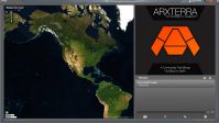
Fig 6. Main Arxterra Control Panel Window

To login, simply click on the Guest# icon, which opens a drop-down login widget (fig 7).  Currently the control panel is in the alpha stage.  The control panel itself is fully functional, but other functions, such as username and password, are not.  At this time, no password is necessary.  To login, the name parameter will simply be the pilot name from the Arxterra App (fig 3).

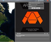
Fig 7. Control Panel Login

Successful login is verified by a marker on the map.  When the marker is selected (fig 8), the robot to be commandeered pops up.  Displaying the name of the robot to be controlled, the status of the robot as the user, and an icon which once selected teleports user to control panel.


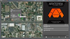
Fig 8. Commandeering of robot


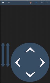
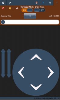
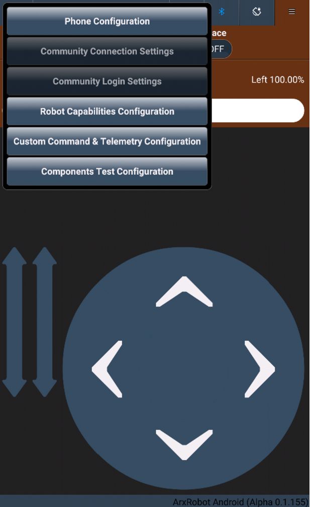
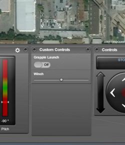
Taking command of the robot shows the GUI of the control panel (fig 9).  The control panel is capable of displaying several telemetry options. For SpiderBot, the video feed component is an important factor, as well as the movement control segment.  Arxterra is capable of more telemetry options such as phone readings, and any custom commands defined by user.  The Arxterra mission control panel could optimize SpiderBot’s aerial video feed by implementing a full screen mode. 

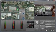
Fig 9.  Arxterra mission control panel


Conclusion:

The Arxterra phone applet and Arxterra mission control panel are seamlessly interfaced.  The ability to control a robot from one or the other is a nice feature to have.  In the case of the Spring 2017 SpiderBot, the requirements are to provide live streaming video for the end of semester games.  This is easily achieved using both the app and control panel.  The Arxterra control panel has the added features of multiple pilots capable of being onboard the robot, as well as a chat feature which will allow for trash talking amongst the robots during the game.


Resources:

  1. http://web.csulb.edu/~hill/ee400d/Technical%20Training%20Series/3DoT/_3DoTTrainingDocumentation.pdf


S17 Prosthetic Hand: Force Sensor Test

The Prosthetic Hand needs feedback in order to control the force of the grasp, therefore we are testing the force sensors to see if they can detect the force difference of the most minuscule item we have to grasp.

Spring 2017 – ArxRobot Custom Commands Update!!

Written By Jefferson Fuentes

Introduction:

The Arxterra app has the option of creating custom commands.  These custom commands allow for a user defined function, to control the robot, not already preloaded onto the app by default. These commands consists of functions such as a simple switch to incremental sliders.  


Requirements:

Spring ’17 SpiderBot is required utilize the Arxterra phone app to control the robot remotely via bluetooth.  SpiderBot is also required to provide aerial live video feed capable of covering the entire arena, as defined by end of semester games to other participating robots.  The video feed will be accomplished by the bots ability to hoist itself up in the air through use of a grappling system.


Procedure:

Creating custom commands on the Arxterra phone app consists of a few finger taps, navigating through the menus, and selecting the appropriate options.  Upon launch of the Arxterra app, the familiar control screen will appear (fig 1).  From here, developer mode must be turned on to create the custom commands required.  By selecting the menu option, on the top right corner, we come to the toggle option for “Developer Mode” (fig 2).


Fig 1. Arxterra initial launch screen           Fig 2. Developer Mode Toggle


After toggling, under the same menu, selecting the gear icon will open another menu.   Selecting the “Custom Command &  Telemetry Configuration” will navigate to the appropriate window to create the custom commands (fig 3). Once selected, a new window appears (fig 4).  This window allows us to add, change order, or edit any custom commands created.

Fig. 3 Custom Command & Telemetry Navigation


Fig 4. Command & Telemetry Options


To create a new command, clicking on the “+” icon will open a menu (fig 5).  Here the required type of command can be selected.  For SpiderBot, one of the custom commands required is the ability to release a grappling hook upon command.  This function would be incorporated using the Boolean command option, single input dual outcome output. When selected,  the app automatically generates a default command (fig 6).


  Fig 5.  Command Selection        Fig 6. Default Custom Command


This default command serves no purpose to the robot and must be edited for proper function.  To edit, the function to be modified is selected, then the pen icon is clicked, prompting a new window (fig 7), where all parameters will be defined.  In this case, SpiderBot requires a command to enable release/launching of a grappling hook, this can be accomplished by implementing a simple switch. The first set of parameters, or properties, consists of the Entity ID is the command ID in HEX, the label, is the name associated with the function, and the default value serves to determine the state of the command upon startup of control panel.  The second set determine where the custom command appears/operates in.  Both are on as this function is needed on both the app and control panel.  

Fig 7.  Command Parameters

The app and control panel determine successful custom command implementation.  The app will show a new icon, the custom command with all defined parameters (fig 8), and a message “Custom command config valid”.  On the control panel, the custom commands will appear in a designated “Custom Controls” box (fig 9).


Fig 8. Arxterra Custom Command         Fig 9. Arxterra Mission Control Panel


Resources:

  1. http://web.csulb.edu/~hill/ee400d/Technical%20Training%20Series/3DoT/19%20Arxterra%20Custom%20Commands.pptx
  2. http://web.csulb.edu/~hill/ee400d/Technical%20Training%20Series/3DoT/20%20Arxterra%20Videos.pdf
  3. http://web.csulb.edu/~hill/ee400d/Technical%20Training%20Series/3DoT/_3DoTTrainingDocumentation.pdf

S17 Prosthetic Hand: Flex Sensor Test

This experiment was done to test the Flex Sensors that we planned to use to control the grasp of the prosthetic hand. In order to make sure they are a viable option, they need to detect a definite difference between different flexion positions of the customers toes. This test helps us determine that viability.

Spring 2017 SpiderBot Material Trade Off Study

Material Trade of Study

By Daniel Matias – Manufacturing Engineer

Table of Contents


Requirements:

A level 1 requirement states that SpiderBot shall lift itself off the ground. To achieve this, and still maintain a stable, mobile robotic platform, SpiderBot will be made of an inexpensive, lightweight material with a high tensile strength.


Introduction

Traditionally walking robots have proven to be a challenge. Proper walking mechanism selection can either means success or failure. Walking robots experience large amounts of shock and vibration that can cause stress fractures and material deformations. The study aims to present all materials considered for SpiderBot’s use.

Materials:

The materials considered in this trade-off are aluminum, acrylic, and plywood. A fixed volume of 1/8’’ thickness, 6’’ wide, and 12’’ long sheets are being used when comparing the materials. Also considered is the strength of the material to ensure our robot will not break under the weight of the components.

Calculations:


The following table shows the cost and mass of the set volume

Material

Cost

Mass

Aluminum

$17.14

398 g

Acrylic

$5.07

174.5 g

Plywood

$2.50

98.8 g

The following is a table of the tensile and compressive strength of the three materials.

Material Tensile Strength Compression Strength
Aluminum 310 MPa 20 GPa
Acrylic 69 MPa 124 MPa
Plywood 31 Mpa 36 MPa

Conclusion:

Although plywood is the cheapest and the lightest, acrylic is more suited for our robot due to the inexpensive, toy requirement. Aluminum could be reduced in size since it is stronger, but the material and machine shop costs would exceed our budget when all the qualities of acrylic can satisfy requirements.

Resources:


https://www.mcmaster.com/#acrylic-sheets/=16uqxrr

https://www.mcmaster.com/#standard-aluminum-sheets/=16uqxy0

http://www.woodworkerssource.com/shop/product/18balpack3.html

http://www2.glemco.com/pdf/NEW_MARTERIAL_LIST/Alumina%206061-T6.pdf

http://www.engineeringtoolbox.com/wood-density-d_40.html

https://www.metalsdepot.com/catalog_search.php?search=s318T6

http://edge.rit.edu/edge/P14418/public/4-Subsystems%20Design/Plywood%20Materials.pdf

http://www.builditsolar.com/References/Glazing/physicalpropertiesAcrylic.pdf

Spring 2017 SpiderBot – DC Motor Trade Off Study

Motor Trade Off Study

By Shaun Pasoz – Electronics & Control Engineer


Table of Contents


Requirements:

Based on the level 1 requirement that all power shall be supplied via the 3DoT board, the motor choices have certain limitations including: must draw 450mA or less, and have an operating voltage of 5V or less.  

UPDATE

Following the Preliminary Design Review the customer requests that SpiderBot’s overall size needs to be reduced. Our initial build had a mass of 858 grams. The SpiderBot team has decided to reduce the overall mass to 500 grams or less. Since our mass has changed, so has the motor torque requirement to make SpiderBot walk. In a future post we will present a systematic process used to determine the torque requirement.


Introduction:

Due to the delicate nature of servos, SpiderBot’s walking mechanism will be driven by two DC motors. DC motors are basic electromechanical devices. They consist of two wires, one for V+ and one for V. The speed, or power level, of the motor is controlled via pulse width modulation (PWM). PWM controls the motor by allowing, for example, full voltage for 50% of a duty cycle to create 50% of the rated RPM. Since the DC motor only has two wires, it provides no feedback. When compared to a servo motor, the servo has: a DC motor, a position sensing unit, and feedback control. However, servos are prone to gear degradation under heavy loads, and size is proportional to cost. This post attempts to deliberate the factors in choosing the correct dc motor for SpiderBot. 


Types of DC Motors:


  • Stepper Motor: A type of DC motors that moves in a predefined step size. They are much more precise, and allow for more control than say a brushless motor. This will not be used in the robot as they are much too bulky for our desired size and weight.
  • Brushless Motor: A motor that utilizes electronic communication to control the current flow through the motor. This will not be used in our robot as it is more complicated to control.
  • Brushed Motor: These are the most common motors and are useful for many applications. They can be used in geared motors which will provide more torque. The increased torque and price are what makes the brushed motor ideal for our robot.


Discussion:

The three main factors in choosing the correct motor comes down to: cost, size, and operating parameters. Out of the three types of DC motors, brushed motors became the immediate choice for the reasons listed under types of DC motors. After the PDR review, it became evident that we needed to shrink the robot and cut as much weight as possible, therefore we will be trying to choose motors that weigh less than 20g. However, smaller motors tend to have less power. Our operating parameters require that the motor operate at 6V or less and have an operating current of under 450mA as this is what the 3DoT can power. After conducting research this is the list of motors that most closely suit what we are looking for:


Motor: Rated Voltage Speed @Rated Voltage Free-run Current   @Rated Voltage Stall Current @Rated Voltage Stall Torque @Rated Voltage Weight: Size  (mm)
Pololu 298:1 Micro Metal Gearmotor MP 6V 75 RPM 40 mA 700 mA 125 oz-in 10.5 g 10x12x26
SparkFun Micro Gearmotor 6V 45 RPM 30 mA 360 mA 40 oz-in 17 g 26x12x10
Solarbotics GM3 224:1 Gear Motor 90 deg. Output 3V-6V 46 RPM 50 mA 733 mA 57 oz-in 31 g 69.4×22.2×18.6
Hobby Motor 3V 6600 RPM 110 mA 800 mA Not Specified 26 g 27x27x33

Table 1: Motor Trade Off Study Data


Conclusion:

In conclusion, the most suitable type of DC motor for our robot is the brushed DC motors. From there the guiding factors for deciding which motors to look at were decided from the limitations of the 3DoT board. For the time being, the motors that are going to be the most viable are the SparkFun Micro Gearmotor, or the Pololu 298:1 Micro Metal Gearmotor. To conduct our initial testing of the miniaturized SpiderBot we will be using the SparkFun Micro Gearmotors as it meets the correct parameters even with a load large enough to stall. Some of the testing will include average current draw under load, and max power test.


Motor 1: https://www.pololu.com/product/2371

Motor 2: https://www.sparkfun.com/products/12285

Motor 3: https://solarbotics.com/product/gm3/

Motor 4: https://www.sparkfun.com/products/11696

Preliminary Project Plan

By Martin Diaz (Project Manager)

Adan Rodriguez (Mission System and Test)

Moses Holley ( Electronics and Control)

John Her (Manufacturing)

Edgardo Villalobos (Solar Manufacturing)

Table of Contents


WBS

By Martin Diaz (PM),

Adan Rodriguez(Mission,Systems)


The work breakdown structure organizes the work needed to complete the project by putting task under each engineer. For our WBS the work of the system engineer was organized into 3 blocks, System Design, Software, and system tests. The work of the ENC engineer was organized into 4 blocks, Electronic Design, Research/Experiments, Microcontroller and PCB, and finally MCU Subsystem and control. The work of the Manufacturing engineer was broken down into  5 blocks, Mechanical Design, Research, 3D simulations, and manufacturing parts and assemblies, and assemble Mini-Pathfinder.


Schedule

By Martin Diaz (PM)

The project schedule was created by using Project Libre. Each Task in the WBS was put as task into Project Libre and then the start and end dates were assigned. When a task depended on a other task to be finished first dependencies were assigned. This can be done by clicking and dragging arrows to other boxes. The program will automatically adjust the task.

Burndown

By Martin Diaz (PM)

The Burndown is a chart that shows how much work is left to complete the project vs time.  The Burndown was calculated by moving the task in the schedule to columns in excel and then assigning the percent completion for each task. The ideal percent completion and real percent completion were then plotted vs time.

Power Allocation

By Adan Rodriguez (Mission and Systems)

John Her (Manufacturing)

Moses Holley (ENC)

Edgardo Villalobos (Solar-Manufacturing)


The power rating for all of the components on the Power Allocation Report list were calculated using specification sheets of corresponding components. We approximated our mission duration to be 1 hour (one fourth the duration of the Pathfinder’s mission due to our rover being one fourth scale in size). Using the specification sheets to find current ratings of the components, we multiplied the current ratings by one hour to calculate power ratings in milliamp-hours. For the motor drivers, we looked at the power consumption of the IC and divided the operating voltage to get the current draw (0.78W/6V=130mA). The I2C I/O Expander is rated for output of 25 milliamps per pin and we will be utilizing 6 pins implying a total power consumption of 150 milliamp-hours. The Project Power Allocation was set to be slightly higher than the total Expected Power. Note that the Project’s Power Allocation value was used to aid in determining which battery to choose for our mission.

Mass Allocation

By Adan Rodriguez (Mission and Systems)

John Her (Manufacturing)

Moses Holley (ENC)

Edgardo Villalobos (Solar-Manufacturing)


Estimates of the 3Dot Board and Custom SMD Board were based off the fact that they are similar in size to the Raspberry-Pi Board (31 millimeters x 66 millimeters). The chassis, solar panel and suspension system were weighed with a scale. Corresponding Sources of expected weights is provided under the Source column. The Project Mass Allocation was set to be slightly higher than the total Expected Weight.

Cost Allocation

By Adan Rodriguez (Mission and Systems)

John Her (Manufacturing)

Moses Holley (ENC)

Edgardo Villalobos (Solar-Manufacturing)


The current battery that we intend to buy may be switched out for a different battery after the Mini Pathfinder is built and tested for its power efficiency. About one third of the products that will make up the Mini Pathfinder will be free of charge due to our team members already possessing certain products. Corresponding sources of expected pricing is provided under the Source column. Because the Mini Pathfinder didn’t have a cost requirement the Project Cost Allocation was set to be slightly higher than the total Expected Cost.

S17 Preliminary Project Plan: Prosthetic Arm

Preliminary Project Plan, with initial work breakdown structure information, system and subsystem level tasks, and system resource reports and cost reports.