
By: Brandon Perez (Missions, Systems, and Test)
Approved By: Ijya Karki (Project Manager)
Table of Contents
This report will cover the interface definition and cable tree.

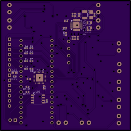
Figure 1. 3DOT Interface Matrix.
On the top, here, we have our interface definition presented at CDR that has been updated to match our final Biped design. On the left, you can see the interface definition of the 3Dot board while on the right, you can see the interface definition for the 16-port GPIO expander that was included onto out custom-built PCB.
One of the changes that we made to the 3Dot interface was removing the second DC motor from the design. We worked with one DC motor to make design work. We attached both legs 180 degrees out of phase to the shaft output of our DC Motor gearbox.
On the GPIO expander, we removed the “body servo” which was supposed to helped shift the center-of-mass either in front of the Biped or behind the Biped when it would walk on inclines or declined, respectively. We omitted that servo because it was causing our Biped to weight up to 1kg with all the mass attached the servo.
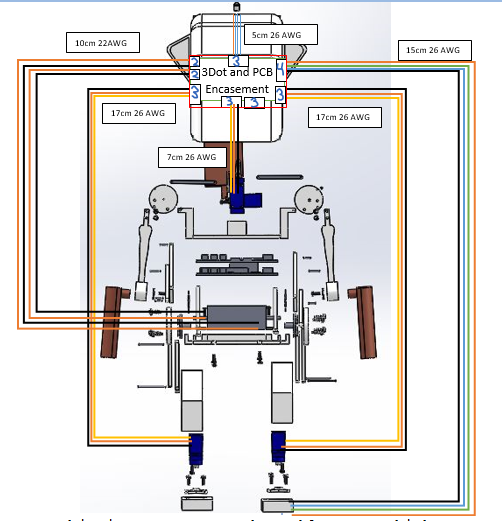
Figure 2. Biped Cable.
Here on this image, we see the Cable tree which corresponds to the final design we have for the Biped. Since the “body servo” was removed, we have removed on set of cabling leading to one of the servos in the center of the figure right below the head. Our wire lengths and type for the servos correspond to the wires that our already on the servos. The cables for the servos are routed out of the head encasement and directly to the servos through a path between the legs. The wires for the color sensor that leads to the foot was the only set that was hand soldered and routed.
The interface definition and cable criteria are described above according to the design for the final Biped.

By: Alan Valles (Electronics and Control)
Approved by: Ijya Karki (Project Manager)
Introduction
The purpose of this document is to show all the updated schematic and hardware changes since CDR.
The Final Hardware design of our robot was slightly different than what we had spec’d for CDR. The Motor stayed the same, it was a pololu 1117 size 130 motor. However, the gearbox that it went into was different. The final motor selected was the Tamiya 907710.[1] This motor was selected based on its gear ratio which was able to provide the Biped with even more torque than the previous model. Our Motor had an output RPM of m 11500 RPM at its shaft. We needed more torque due to the fact that our latest linkage design was larger/ longer than the previous design. The Tamiya 70110 4-speed Crank Axle Gearbox Kit had 4 ratio option, 5402:1, 126:1,441:1 and 1543:1.
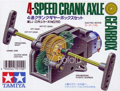
Figure 1. Speed Crank Axle.
These ratios dropped the output RPM to 2.2, 7.45, 27, and 16RPM respectively.
The only observed issue with this gearbox was that the gears internally seemed to be rubbing together when under large amounts of mechanical load. I noticed that there was an unsettling amount of play in the gears when it was put together.

Figure 2. Gearbox.
I suspect that once the load past a certain limit, the gears shifted to the left touched the high RPM green gear. This caused a clicking sound during random intervals of the walking motion.
Figure 3. Battery.
The battery was changed to a hobby people 7.4v 800mA Battery.[2] This battery was chosen over our previous battery because, we did not have to wait for shipping. Lithium batteries have a risk of catching fire which means that they are not shipped by air, only on trucks. Thus, it was much easier to go to the physical location of hobby people and purchase the needed battery and connector right on the spot. The form factor of the battery was absolutely perfect for our design as well. It had the dimensions of 12x35x68 mmm and weighted around 50g. Thus it was the perfect size for a RC Biped. Also, the pololu 117 motor had around 550mA operational current when attached to the 70110 gearbox. This was done by measuring it with a Digital Multimeter. Therefore, a rough calculation of power would be 650mA*5V = 3.25 W and the battery has a capacity of 7.4* 800mAH = 5.92 Wh. Thus, the battery still appears to meet our requirements that state we should play the game for an hour.
Conclusion
In Conclusion, The Battery and motor were changed to the hobby people 2S Lip and the Tamiya 70110 gearbox, respectively. This was done to increase the realized torque demand of the linkage assembly which was updated in order to meet customer request.
References
[1] https://www.pololu.com/product/68
[2] http://www.hobbypeople.net/index.php/hobby-people-7-4v-800mah-2s-30c-lipo-battery-bec-plug.html
[3] http://arxterra.com/fall-2016-biped-updated-motor-study/

By: Alan Valles (Electronics and Control)
Approved By: Ijya Karki (Project Manager)
Table of Contents
The purpose of this document is to demonstrate software logic behind the Biped.
The Fall 2016 Biped had a requirement which stated that the Biped had to be controlled using RC mode in the Arxterra App. The main feature of the app is a directional pad which is controlled by the Move Command. There is also a capability of adding Custom Commands. Electronics and System Engineers had several ideas and thought about the best way to utilize these. However, the backbone of our software and electronics subsystem design is a rotary position sensor. The selected rotary position sensor is the Bourns 3382. The rotary position sensor is a potentiometer that can spin forward up to 100000 cycles.[1]This means the inner rotor can be spinning freely.[1] All of the logic to be implemented is dependent on the readings of this value. As shown in the diagram below. The unsigned integer values between 0 and 1642. This value can be changed by setting the gain of the ADS1015 A2D converter in the set up loop. Therefore, logic can be implemented to control the robot in 330/360 of its walking motion.
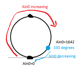
Figure 1. Encoder Value
Thus, as the encoder value increases or decreases we continue to check to position and move the arms to the side of the foot that is planted. Ain0 shown in the picture above correlate to the variable adc0.
Poll a2d converter after every loop.
![]()
Based on position of walking motion i.e. shaft position, adjust arms accordingly.

Essentially when the user presses forward on rc mode in the move command, the robot will move and if the robot is on its left foot, the arms will move to left side and if on right foot, the arms will move to right side.
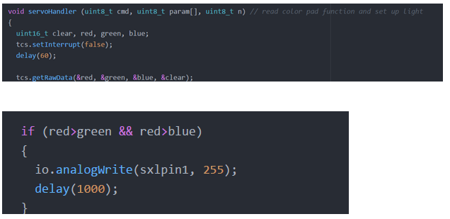
Also, the servohandler custom command was overridden to read color sensor and display LED using sx1509 gpio library. The final design was meant to use millis function inside loop as shown in reference [2]. It was commented out in the code that is uploaded to the zip file.
In conclusion, these are some of the code snippets for the Biped Group Design. Please see the Zip file for more information or our previous software blog post for library information.[3]
[1] http://www.bourns.com/pdfs/3382.pdf
[2] https://www.arduino.cc/en/Tutorial/BlinkWithoutDelay
[3] https://www.arxterra.com/fall-2016-biped-codesoftware-update/
[1] Biped Code


By Ridwan Maassarani (Design and Manufacturing)
Approved by Inna Echual (Project Manager)
As a requirement, solar panels had to be manufactured that is of the same form factor as the spirit and opportunity mars rovers that were designed by NASA. To accomplish this, my team and I visited JPL and was able to find model at their museum. In addition, a small scale model was purchased from the gift shop for taking measurements later on if needed.

Figure 1: Small-Scale Model from JPL

Figure 2: High-Quality Rendering Photo (top view)
Figure 3: Spirit Rover Dimensionas
I was also able to obtain a schematic picture by contacting the same individual who made the high quality rendering pictures. Here’s is the website for more information: http://v5.nicksotiriadis.gr/mars-rover-project/
From all this information, I took measurements and a ratio of 10 was used based on the requirement that the panels needed to fit a 19-inch-wide cabinet and to the panels were scaled accordingly in SolidWorks using the scale feature.
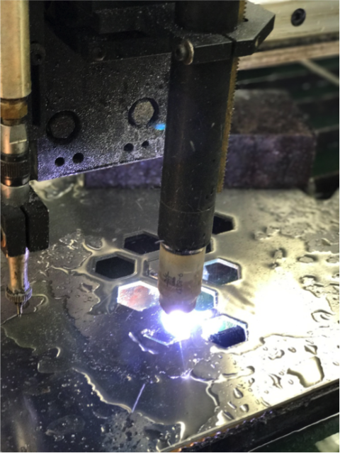
After the dimensions of the panels was established, a folding mechanism had to be devised to fulfill the cocooning state requirement. From my earlier blog post, I go over the various type of gears and types of mechanism that could perform a folding motion but utilizing worm gears for their high torque and self-locking feature was the best choice. First, torque needed to be transferred to the panels from the gears. The best option was to schedule an appointment with the mechanical design center and weld the rod to one leaf of the hinge. I tried to do this many times but failed since Electrical Engineering students do not normally get help from the mechanical center so there was no fluid was to get help. This forced the use of an epoxy called JB weld, used as a welding alternative for metals which by the end of the semester failed. In future 400D project, I hope the mechanical center will become a place where students can get their designs manufactured with ease. I have stablished some kind of relationship with Joe, the person who runs all the equipment such as welding, drilling, and plasma cutting. Here’s are my panels cut using their plasma cutter:

After making a connection from rod to panel, the gear needed to be attached firmly to the rod so that when the worm rod spins, torque is delivered to the gear, rod, and finally the panel. Ideally, metal gears need to have a press fit such as stepper motors in a printer. Press fitting gears is a science and there was no time nor the budget to get custom sized gears. So, a hollow rod was purchased from home depot and fitted in the gears bore to get a better fit from gear to rod as well as from worm rod to stepper shaft. The gears came with a set screw; this was used to secure the gears further. Since this is not the best method of connecting these gears, epoxy was used again for safe measure. For the next semester, I would recommend researching how to securely connect the gear to the shaft, rod to hinge, and worm rod to stepper shaft. Another improvement would be to make a gear box for these gears, this will serve as an encasement as well as a place to fill grease so that they are always lubed. Having lubed gears will prevent any friction between the teeth, it is crucial for metal gears.
In conclusion, another improvement would be to limit the amount of freedom the hinge has when unfolded. This can be done by welding some metal between the main panel and the right panel, this will help when the rover is being operated at the same time the panels are installed. It will remove the additional torque generated when the rover is being operated.
By Ridwan Maassarani (Design and Manufacturing)
Approved by Inna Echual (Project Manager)
A custom PCB that can drive five stepper motors was needed to reduce the footprint on the rover. The custom PCB would also cut down on cost since stepper motor drivers that can run 3 or more motors can gen expensive. It was also difficult to find a motor driver than can run five motors. So, a custom PCB was made based on the A4988 stepper motor drivers capable of driving two coils.