Coverage Angle Test

By: Victoria Osaji, Manufacturing and Development Engineer

Table of Contents

Design Analysis:

Introduction:

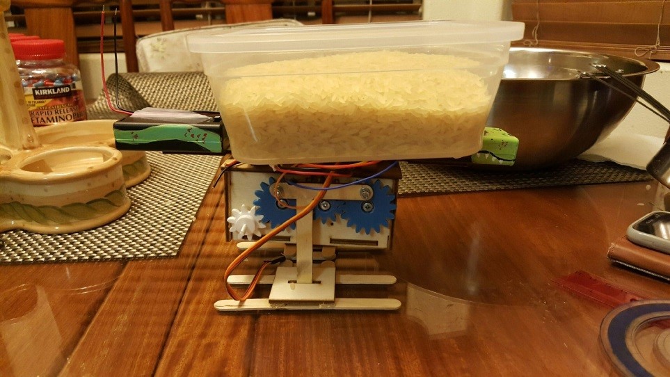
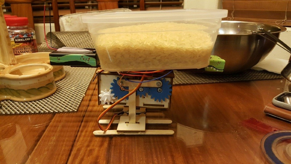
This was one of the four tests we conducted to demonstrate the mechanical capabilities of our robot dinosaur. In this test we are looking to determine the radius our robot head can cover essentially measuring what areas our robot can see as it moves its head around. This way we know the limitations on the robot head so as not to damage any of the linkages or the internal components which are tied together

Process:

 coveangle

Parts needed:

  • Flat surface area
  • Protractor to measure out the radius angle
  • Ruler


In order to measure the coverage angle the steps and measures we took are show below:

1. Set your robot head to the middle of your robot and mark that distance
2. Move your robot head as far to the left as possible without moving the body. Mark that spot.
3. Move your robot head as far right as possible without moving the body. Mark that spot.
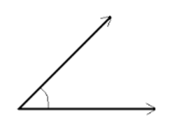
4. With a protractor measure the angle covered from the left to the right.
5. This is the range that your robot can visually cover.

We repeat this exercise a few more times to validate the range we are getting on the robot


Results:

What we noticed is our robot moved 160 degrees to the right when turned and in the reverse direction 20 degrees to the left when turned. On average the consistent rotational angle we saw was 140 degrees. We repeated the exercise and had several numbers in ranges of 138degrees all the way to 142 degrees (we had about 8 different tests conducted). Therefore our 140 degree was an average of the all the samples we attained.

Conclusion:

All in all, there are several important factors for why we want to know what our coverage angle. We do not want damage linkages or any parts of our robots by awkwardly turning it in directions it is not able to go. Therefore understanding what our limitations are with regards to knowing what our coverage angle is will help to protect our robot.

Load Capacity Test

By Victoria Osaji, Manufacturing and Development Engineer

Table of Contents

Introduction:

This was another one of the four tests we conducted to demonstrate the mechanical capabilities of our robot dinosaur. In this test we are looking to determine the load the robot can sustain without any significant damage or falling apart. This way we know the limitations on the robot support so as not to damage any of the linkages or the internal components which are tied together or put unnecessary strain on the legs.

Process:

load1

Figure 1: One of the load tests conducted on our robot.

Parts needed:

  • A bowl to hold the load
  • A system of weighted measure (in our case we used cups of rice)
  • A scale to measure the weights
  • A flat surface to balance your robot


load2

Figure 2: Another one of the tests conducted. Using a heavier weighted sample

In order to determine what the load capacity of our robot was, the steps we took were:

1. Get pieces of wood with varying weights. (Always better to use a flat piece of wood but you can also use a flat piece of metal or any weighted substance – we used a bowl of rice)
2. Weigh the piece first and then place on top of robot.
3. Ensure that your robot maintains its balance and doesn’t tip over.
4. If it doesn’t lose the support, move on to another piece of wood. One that is preferably heavier than the last one used.
5. Continue this until your robot shows fatigue or an inability to maintain support.

Results:

Our tests results showed the following:

Weight 1 200g
Weight 2 383g
Weight 3 570g
Weight 4 761g
Weight 5 950g
Weight 6 1.25kg
Weight 7 1.54kg
Weight 8 1.745kg


At about weight 8 we started to see a significant dip in the legs of our robot where it started to diminish.  This is where we noticed our first major pressure point. As a result of not wanting to have to put our entire robot all over again from scratch we decided that this would be the load capacity for our robot.


Conclusion:

The load capacity is extremely important to the overall weight and support of the entire robot. It is important to note the limitations on what your robot is capable of and what your robot is able to lift and support that way we don’t compromise the entire structure of the robot.


Design for Feet Trade-Off Study:

By: Victoria Osaji, Manufacturing and Development Engineer

Introduction:

The foot of the raptor is probably the most important piece to the animal. This determines the most support for the center of mass and gravity for the raptor. Based on this ideology, we thought about three different types of design for the foot of our raptor.

Level 1 System below:

S1. The 3rd generation velociraptor shall statically walk on a flat surface of linoleum

S2. The 3rd generation velociraptor shall statically walk on a flat surface of cardboard.

S3. The 3rd generation velociraptor shall statically walk on an incline and decline surface of 6.5 degree maximum

S4. The 3rd generation velociraptor shall perform static walking while on a step of .5cm.

D1. The 3rd generation velociraptor should statically walk on a flat surface of linoleum

D2. The 3rd generation velociraptor should statically walk on a flat surface of cardboard.

D3. The 3rd generation velociraptor should statically walk on an incline and decline surface of 6.5 degree maximum

D4. The 3rd generation velociraptor should perform static walking while on a step of .5cm.

For one design we thought of a splined/sloped design. We decided that a curvature at the bottom of the feet may allow the best stability for our raptor. We tried to simulate the feet of humans in this scenario. Most human feet are actually not flat and are more or less splined or curvy and we figured we would duplicate this idea in creating our raptor. The advantages to this idea were minimal at best, while it was the most similar to humans it didn’t offer as much support or foundation for the center of mass for our raptor and when looking at it mechanically it actually would not be easiest design to translate mechanically.

For another design, we thought of a flat surface as the base of the foot of the raptor. In order to support the weight of the raptor we decided that we would need a square base foundation that would support that weight. Also we felt that we would be able to ensure that our raptor would be able to balance better in case of a battle with another dinosaur. However we notice that there would be discrepancies with this design. In the event of a battle, as much a flat base may not provide the best balance, while it would provide some balance it may not be the best. Also when it comes to navigation, a flat surface base as the foot may not provide the best grip for unlevelled surfaces, this may cause the raptor to tilt and fall in areas as such. So then we thought why not a flat surface with spiked feet. This would still give us the strong square- base foundation to which our raptor would be supported which is based off the weight of our raptor as well as the benefits of having spiked feet. With the spiked feet, we would allow the dinosaur to have enough grips as it navigates through different locations. It would also allow for the raptor to use as a weapon in case of a battle. Ideally, this would make the most sense and would satisfy all the components we are looking for our raptor to have.

References:

https://www.arxterra.com/spring-2016-velociraptor-hardware-simulation/

http://sites.uci.edu/markplecnik/projects/leg_mechanisms/leg_designs/

Materials Trade-Off Study:

By: Victoria Osaji, Manufacturing and Development

Introduction:

The previous semester, spring 2016, did a very detailed material trade-off study that we liked based on Aluminum and PLA Filament (3D printing material). We found this very useful because we have ideas that we can now build off of.

Although, our design may differ in some places and our requirements have changed a bit these are still information we can use because the basics requirements are covered such as walking statically and dynamically and being able to walk up and down uneven surfaces. What I really liked most is that they used the two different materials depending on their needs. They used the aluminum for their bottom piece because they wanted to maximize the weight on the head and tail. Then they used the PLA filament for the foot that way the robot could walk statically and dynamically without slipping on different surfaces.

References:

Leg Design:

By: Victoria Osaji, Manufacturing and Development Engineer

Table of Contents

Introduction:

The legs are one of the most important and complicated parts of this project. I mean without legs or not being able to control the robot the project would not meet a lot of requirements and it would not work. So we took this very seriously.

Level 2 Subsystem below:

14. 3rd Generation Velociraptor (Th) shall have a leg design that can support the mass at 505.5g at different positions for standing, bent, and crouching.

Design 1:

legdesign1

Figure 1: This design was modeled after the UCI linkages.

These legs were the image in Figure 1. At first I was having trouble designing these legs because I didn’t understand completely how they worked. But as I did more research, I realized the UCI linkages were all about the circular motion Click Here.


legmechanism

Figure: The model for design 1.

Understanding that, I found a design to reference online. The reason we did not use these legs is because I was having issues simulating the walking pattern on solidworks, I am not sure if there was too much or too little traction. So I decided to 3D print it just to see if I can fix the issue manually. I think the problems stem from the dimensions and the sizing of the legs. I didn’t have any exact measurement, I just eyeballed it and you cannot do that with these robots because they are very sensitive in that sense.  Fabian, the President of the Wednesday class, tried to improve this design by making his own. The appearance was better when I simulated it on solidworks the walking pattern was inversed. To conclude, we were unable to use this design.

Design 2:

The next design I modeled on solidworks also was the Theo Jensen model.

Design 3:

This design was also modeled after a model I found on youtube, the Stephenson. For this model I printed out screenshots of the legs from online and measured out every part so I could recreate them on solidworks. The legs consisted of different size triangles, 4 links and 1 one oddly shaped piece plus the foot . The holes for all the connections were 3mm. These legs actually moved on solidworks however they were not doing the complete walking motion so I 3D printed them to manually play with them and I noticed the same thing.


References:

http://sites.uci.edu/markplecnik/projects/leg_mechanisms/

Gear Train:

By: Victoria Osaji, Manufacturing and Development Engineer

Introduction:

The mechanical system we implemented was the gear train and it was designed to move the legs, head and tail. For the legs, the small gears have 10 teethes and big gears have 16 teethes. One of the small gears is actually a motor coupler as well that connects to the GM9 motor that will then drive the other gears to move.

Level 2 Subsystem below:

8. 3rd Generation Velociraptor (Th) shall control the head and tail movement with a single servo using gear trains.

11. 3rd Generation Velociraptor (Th) should control the body platform movement with a single servo using gear trains.

Motor Calculations:

gearcalcimage

To conclude, we will use 56 RPM at 3.7 Volts to drive the small gears to big gears. Since we have 35 RPM, (35RPM/60sec) =0.583 cycle per second for the big gears.

References:

http://www.engr.ncsu.edu/mes/media/pdf/gears