By: Lam Nguyen (Project Manager)
Hal Vongsahom (System Engineer)
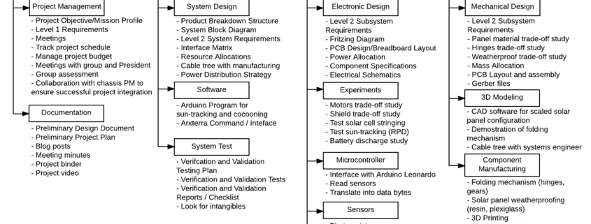
Work Breakdown Structure (WBS)
By: Lam Nguyen (Project Manager)
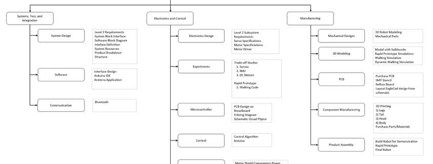
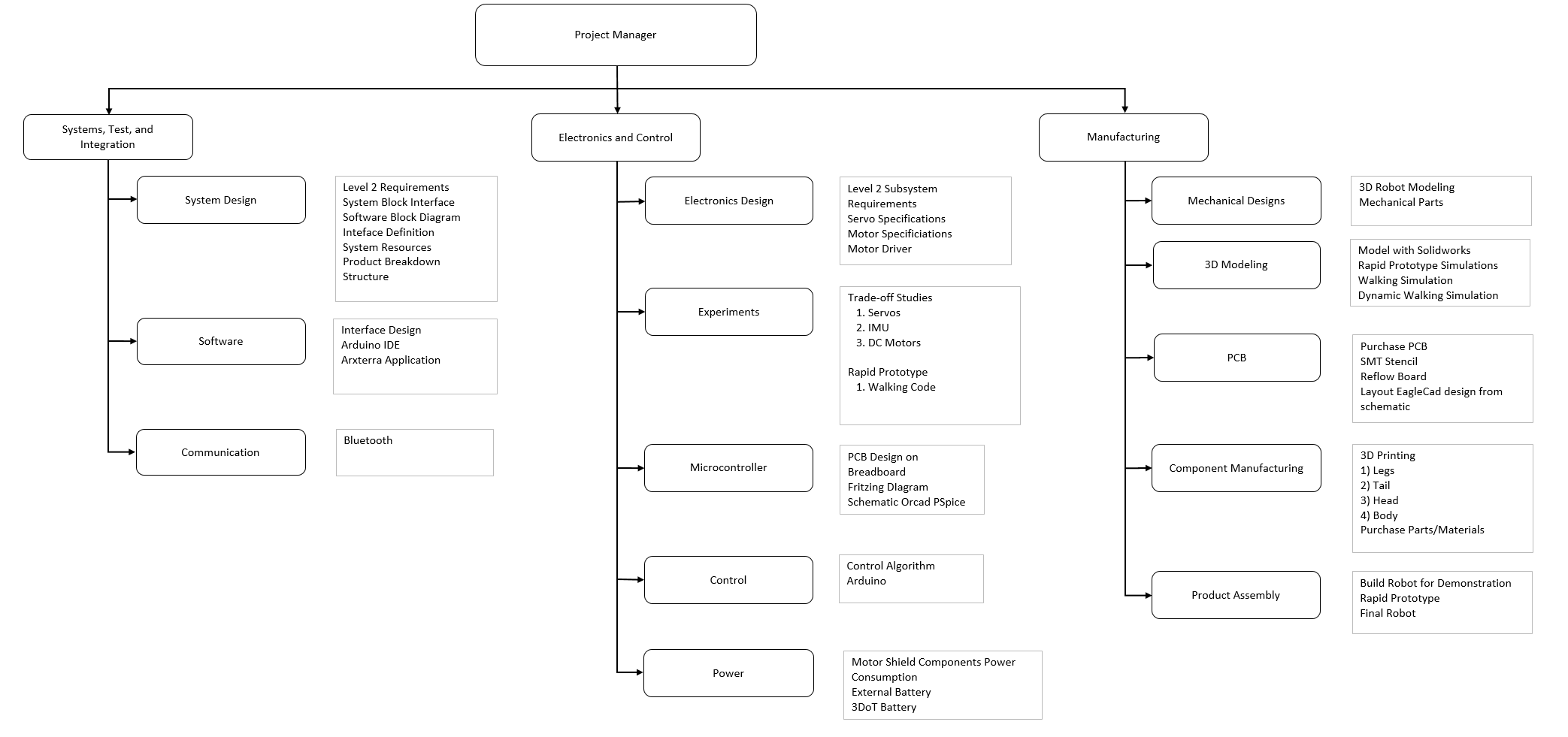
The Work Breakdown Structure in Figure 1 organize specific tasks to three section for the Velociraptor project. These three sections are assigned to division members in Mission, System, and Test, Electronics and Control, and Manufacturer. The overall diagrgam is overseen by the Velociraptor’s Project Manager to delegate these task to each division member. Each branch lists the responsiblity of the division member to meet the overall objective in completing the project.
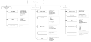
Figure 1
Project Schedule
By: Lam Nguyen (Project Manager)
In order to meet deadlines for the Velociraptor Project, a project schedule was made to keep track of completed tasks. This schedule will not only benefit both the project manager and the division members but will also help move the project forward to build the robot.
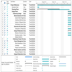
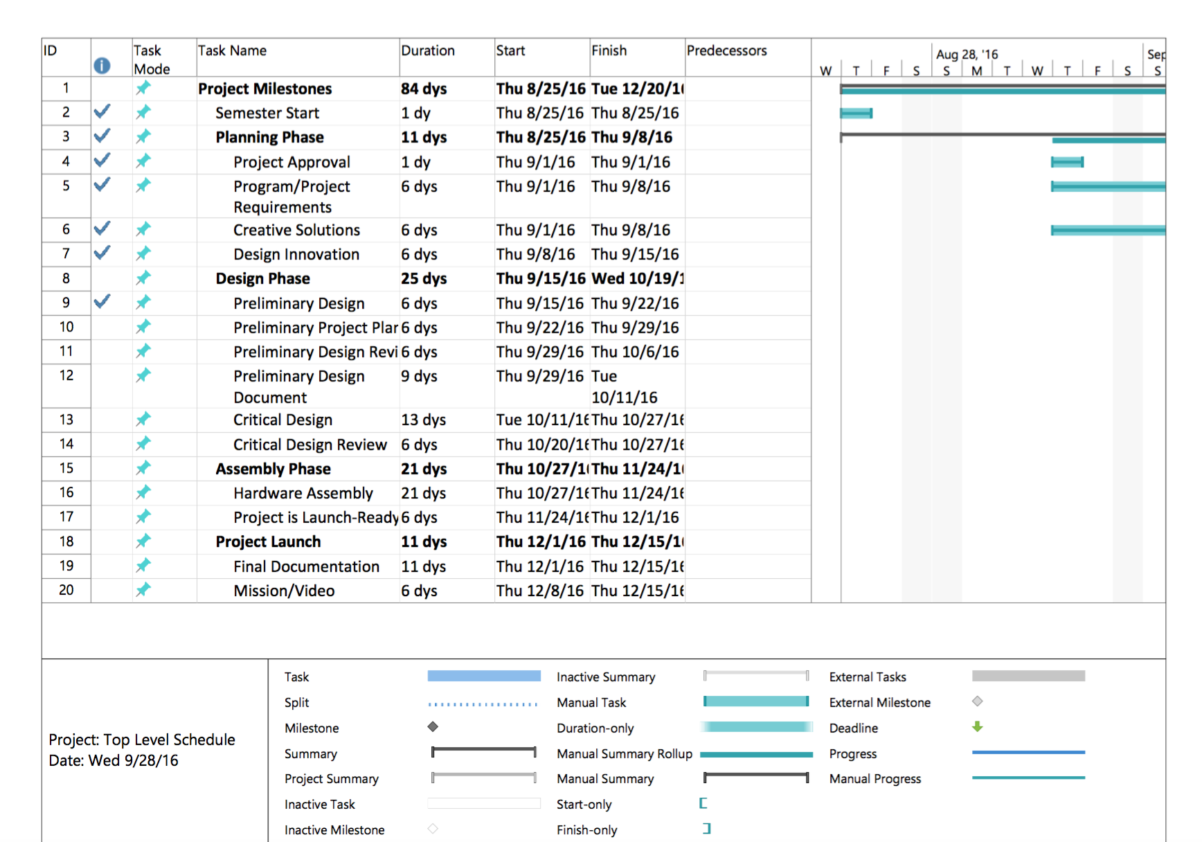
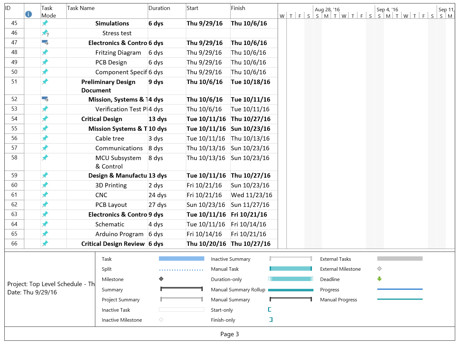
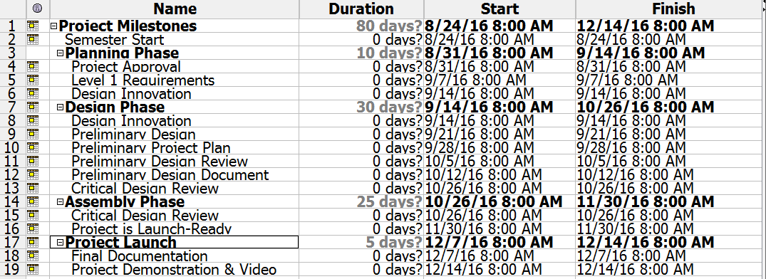
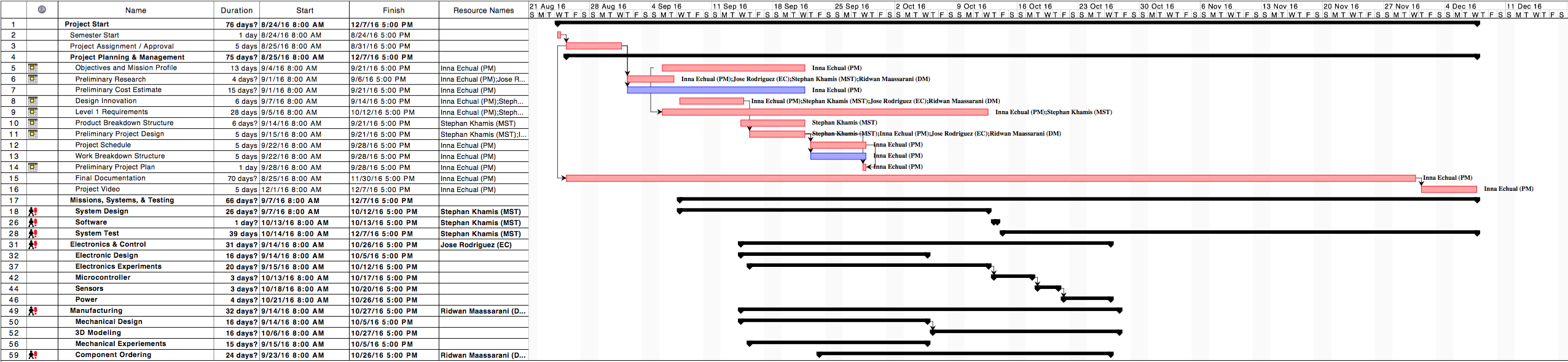
Top Level Schedule
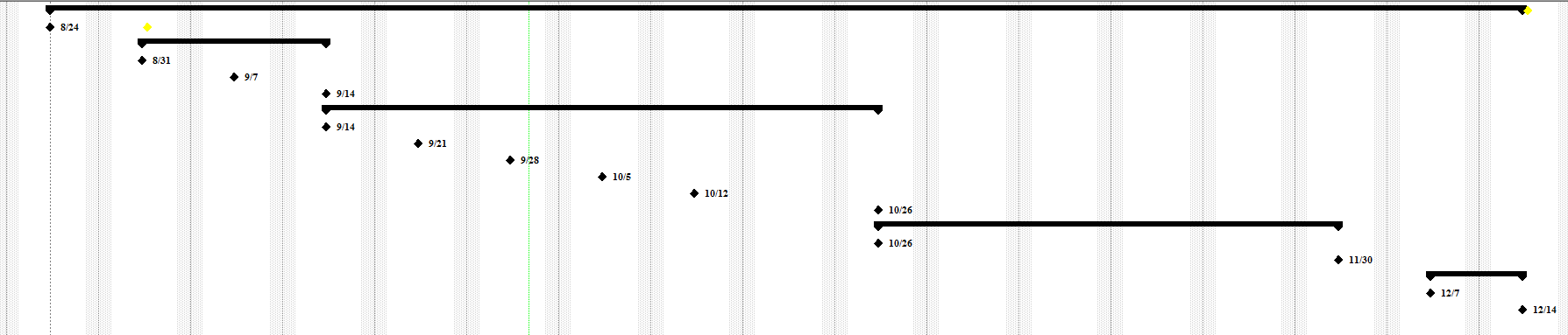
Top Level Schedule was created to keep track of tasks the project manager assigns each team member in Figure 2. Each task has a projected deadline assigned to each division member. Each deadline that is completed will help guide the team to focus on tasks unattended. The overview timeline of project in Figure 3 shows

Figure 2
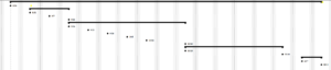
Figure 3
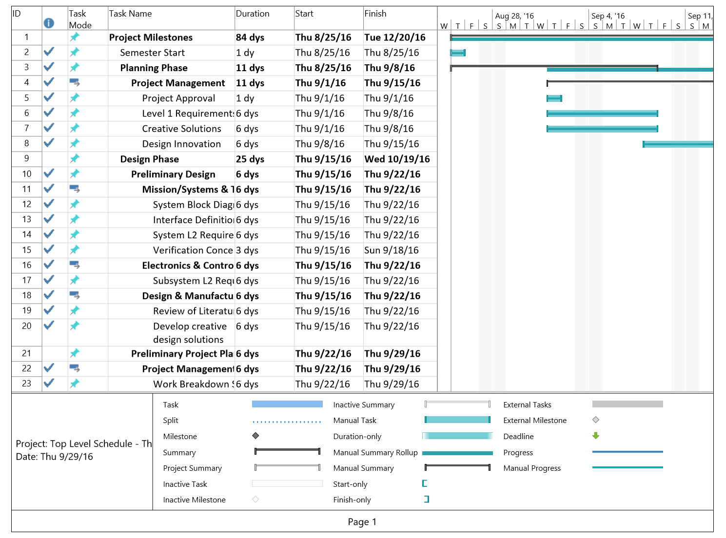
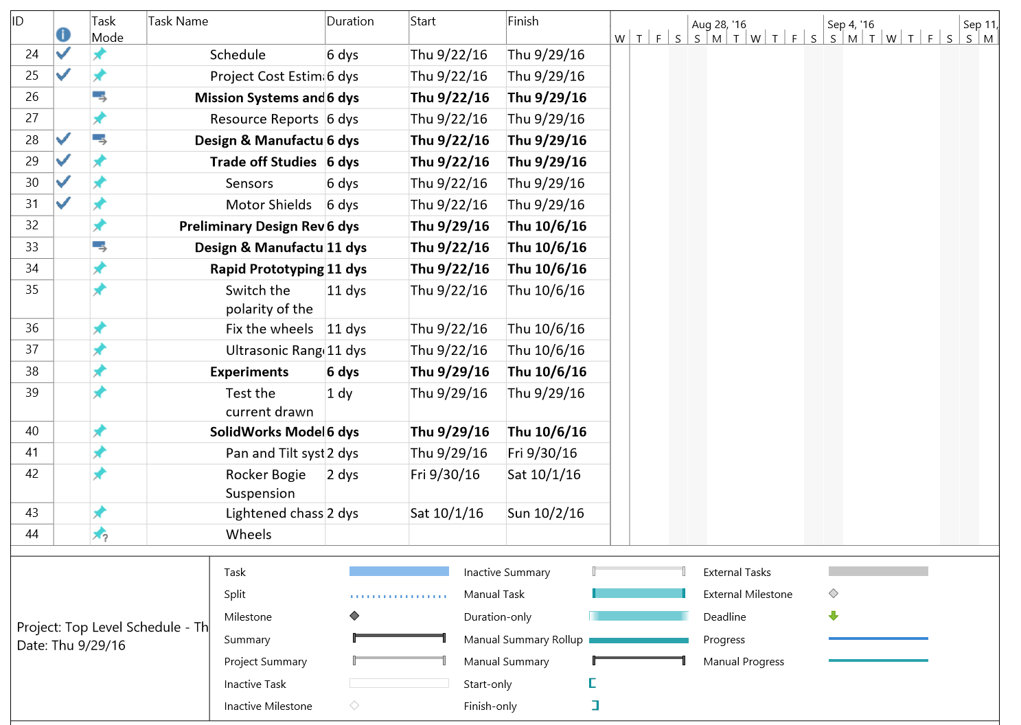
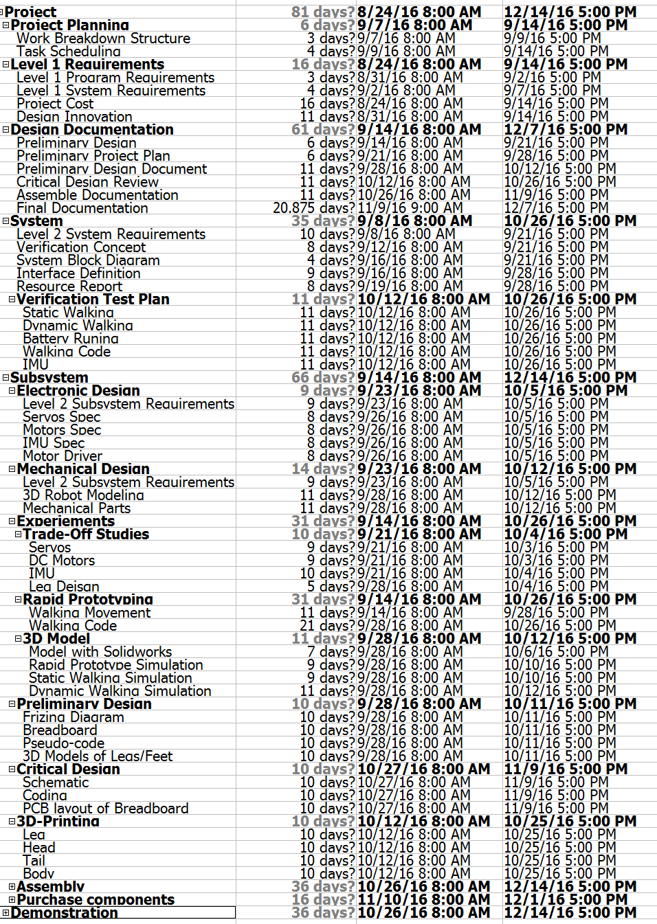
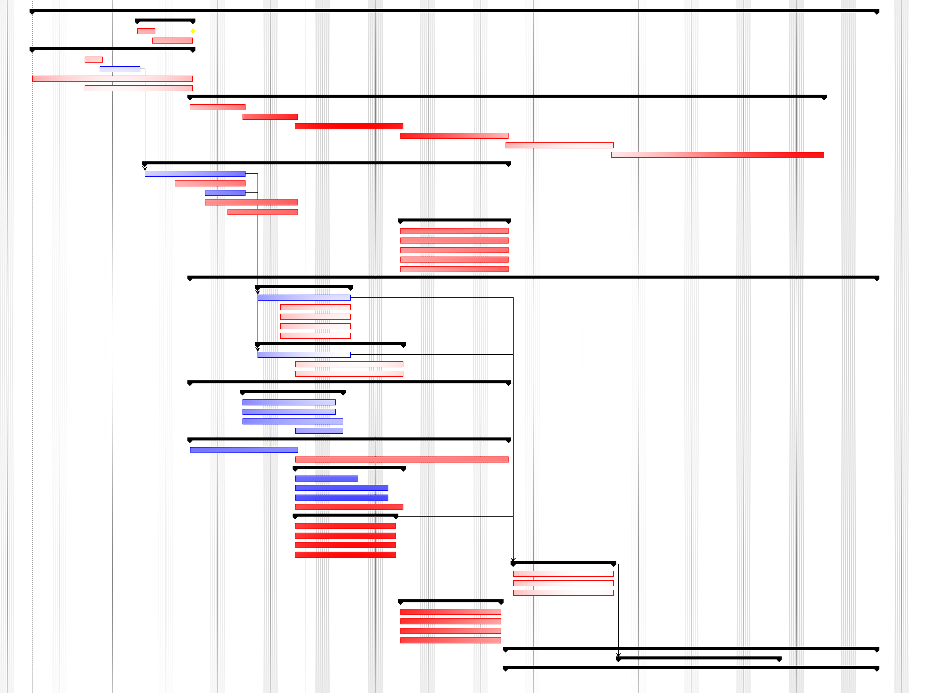
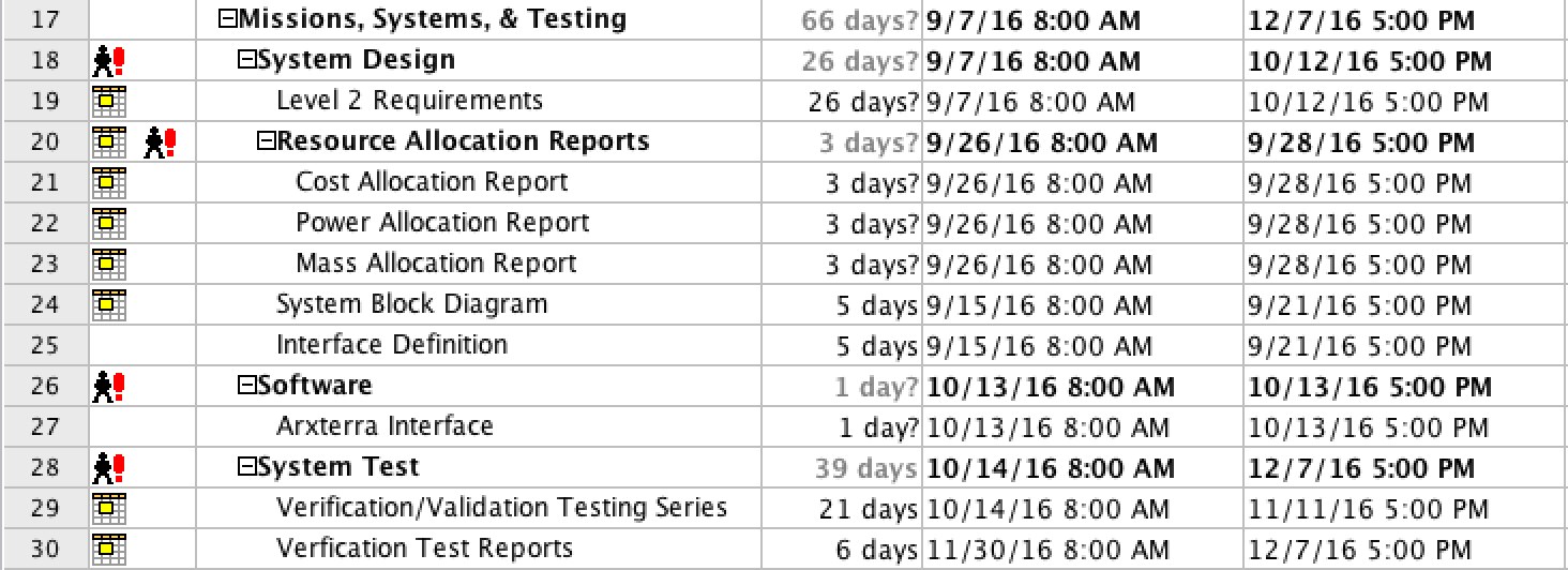
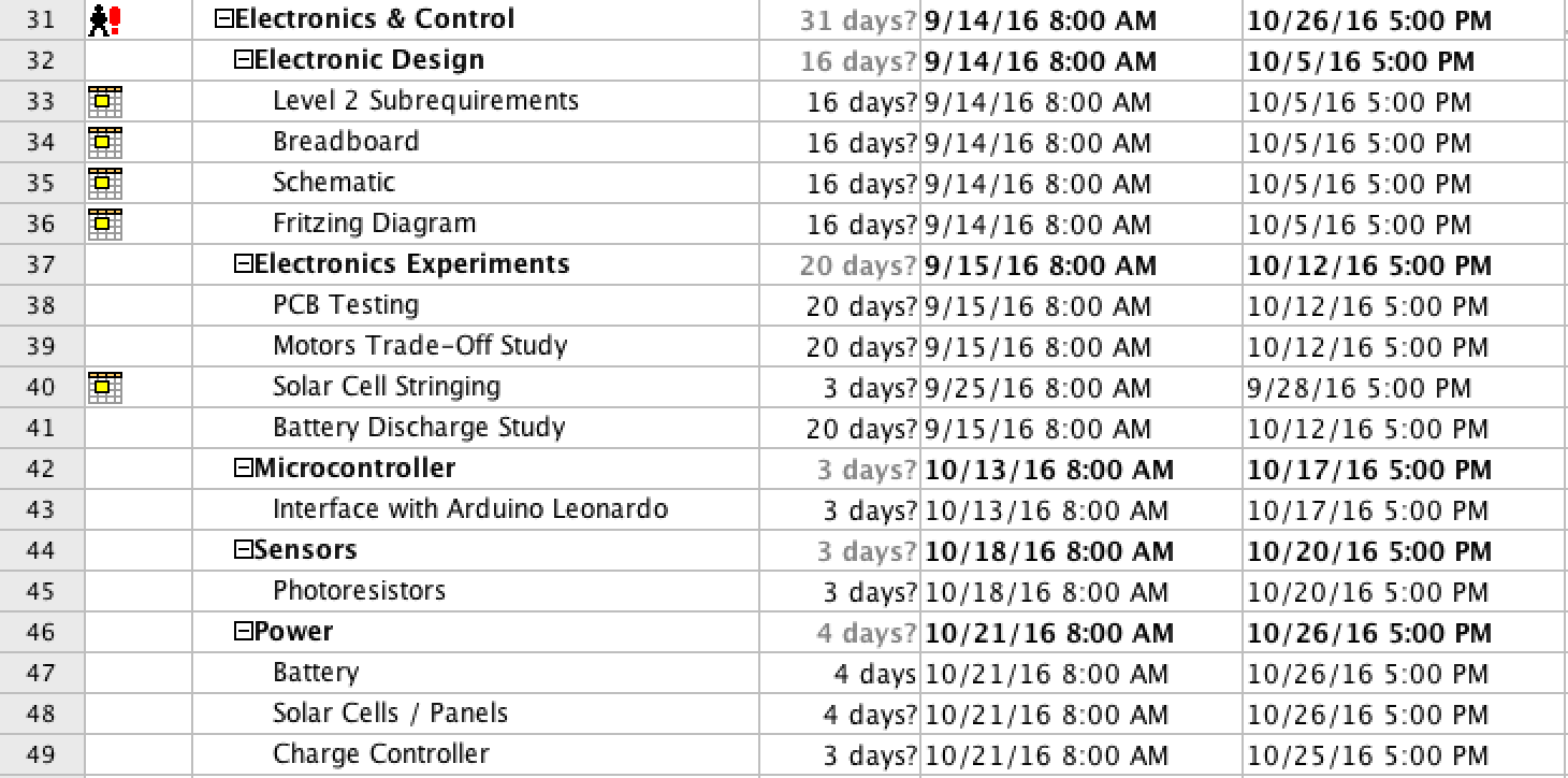
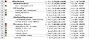
System/Subsystem Level Tasks
The System/Subsystem Level Tasks outlines the tasks for each division member and provides a projected time for each division members.
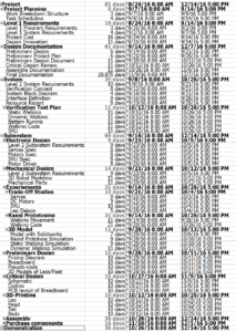
Figure 3
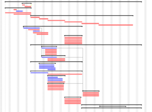
Figure 4
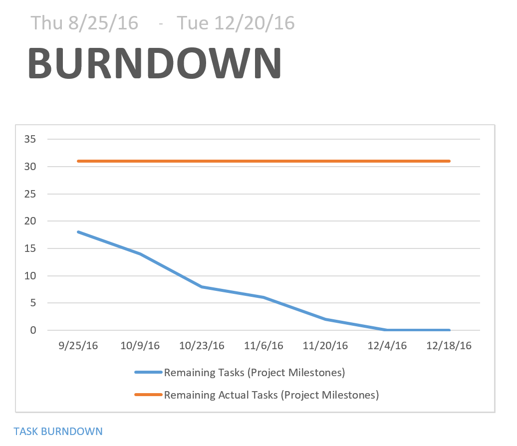
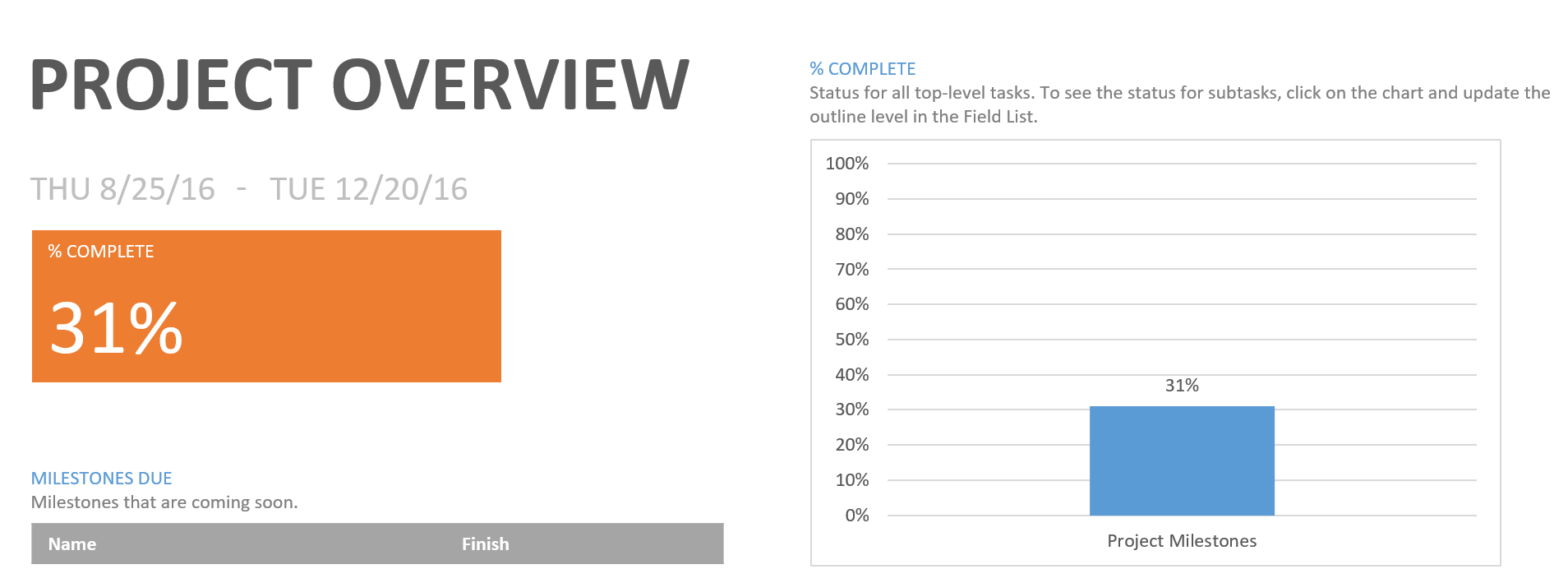
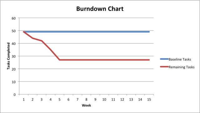
Burn Down and Project Percent Completion
(TBA)
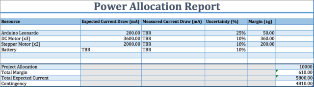
System Resource Reports
By: Hal Vongsahom (System Engineer)
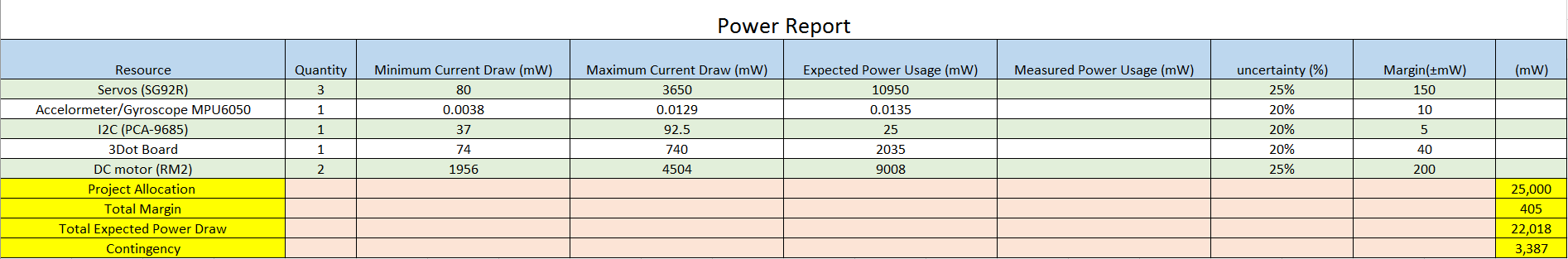
Power Report
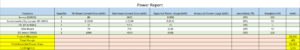
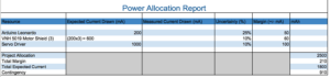
Figure 5
The power report is an overview of the initial power draw of the system. However, an important note is that the manufacture website or data sheet only listed power draw in current for all the components. Therefore, the power draw was calculated using Ohm’s law. The power report has a minimum and maximum power draw. A minimum power draw is when the velociraptor is not walking. A maximum power draw is when the velociraptor is walking. The measured power column is left blank at this moment. The group have not obtained any of the hardware to physical measure the current draw. However, the expected margin can give a rough estimate of the actually current.
The servos power draw was collected from the manufacture web site [1]. A total of three servos will be used. One servo to control the head, the second to control the tail, and the third is to control the threaded rod that will shift the center of mass accordingly. The total power draw for the three servos use the most power of the entire system.
The two DC motor comes second in drawing the most power for the system. The data was collected from the hardware website [2]. One DC motor will use for the right leg, and the other DC motor for the left leg.
The I2C and the MPU-6050 data was collected from the manufacture data sheet [3, 4]. The power draw for the I2C and MPU-6050 are not significant.
The 3Dot board data was collected from last semester Spider bot [5]. The Spider bot also use a 3Dot board last semester and measured actually values to verify that the ranges are correct. As a result, the velociraptor may use Spider bot data to factor into our initial power estimate.
Overall, the power is sufficient to operate the system. In addition, a 3,387 mW contingency is available for the system for other uncertainty.
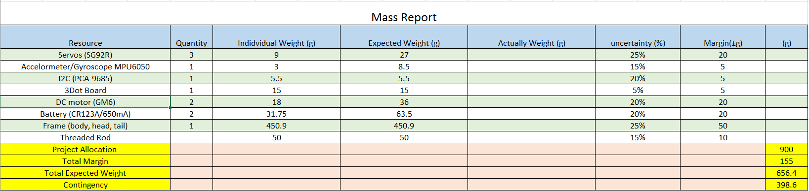
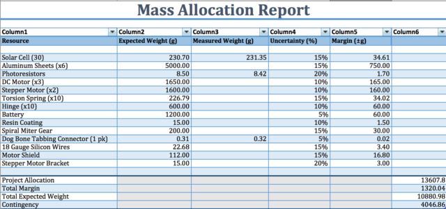
Mass Report
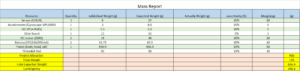
Figure 6
The goal of this semester velociraptor is to weigh less than 900 grams. The mass of the MPU-6050 was gathered from the manufactured data sheet [3]. The mass of the MPU-6050 is very small and does not factor heavily in the project. The mass of the I2C is collected from the website [4]. The mass of the I2C also plays a small part. The mass of the 3Dot board was collected from the Spider bot last semester. Again, they were able to accurately measure the mass of the 3Dot board which justify it in this report.
The mass of the servo is collected from the manufactured website [1]. Since the quantity is in three, and it is acting as the velociraptor muscle. This add a decent amount of weight to the project. The DC motor mass was also collected from the website [2]. The quantity of the DC motor is two and adds 36 grams to the project. The battery mass of the battery is found online data sheet [6]. There will be two battery use in this project which ass 63.5 grams which is the second highest mass in the project.
The largest mass comes from the frame of the velociraptor. The frame of the mass was calculated using the total mass of the previous semester project minus the components mass of this semester [7]. The justification for using last semester mass is because their project was successful, therefore, this semester can factor that into this mass report for a good estimation.
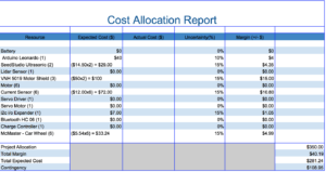
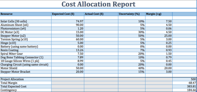
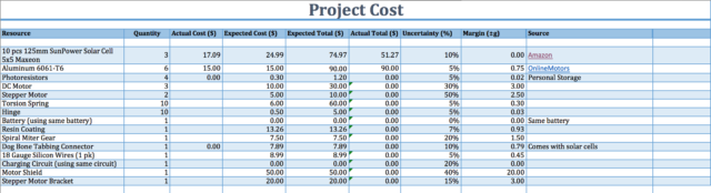
Project Cost Estimate
By: Hal Vongsahom (System Engineer)
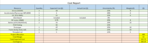
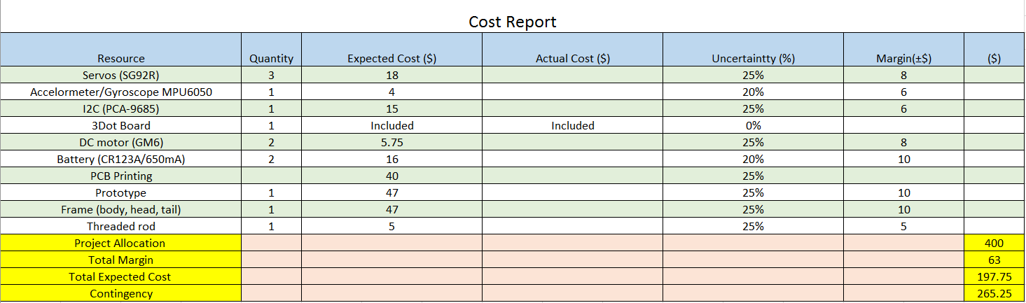
Figure 7
The total project budget for this velociraptor project is 400 dollars. The PCB, Frame, and prototype cost for this semester velociraptor cost report was borrowed from last semester velociraptor [7]. Last semester project actually spent the funds approved by the customer. Therefore, a good estimation can be calculated in this cost report. Also to note, these parts are the most expensive resources of the project.
The MPU-6050, I2C, Battery, servo, threaded rod, and DC motor cost was collected from the retailer’s website [3,4,6,2,3,1]. The DC motor and servo are the second most expensive component for this project. The data for the system resource reports link mass and cost together. The more mass the component has, the more cost that component shall have as well.
Last note, the 3Dot board is provided by the customer, therefore, it is not factor in the cost.
Overall the initial cost is well within the project budget with enough budget to cover addition cost for uncertainty.
Resources
[1] Addicore SG90 9g Mini Servo. (n.d.). Retrieved September 28, 2016, from http://www.addicore.com/Addicore-SG90-Mini-Servo-p/113.htm
[2] https://www.pololu.com/product/182/specs
[3] https://www.cdiweb.com/datasheets/invensense/PS-MPU-6000A.pdf
[4] https://cdn-shop.adafruit.com/datasheets/PCA9685.pdf
[5] https://www.arxterra.com/spring-2016-3dot-spider-bot-preliminary-design-document/
[6] https://www.bhphotovideo.com/bnh/controller/home?O=&sku=1018868&gclid=Cj0KEQjw1K2_BRC0s6jtgJzB-aMBEiQA-WzDMZ4G93fpLNmiUX-CGjONHm0czidWkbbSiUMk3B_luoAaAqM68P8HAQ&Q=&ap=y&m=Y&c3api=1876%2C92051678402%2C&is=REG&A=details
[7] https://www.arxterra.com/spring-2016-velociraptor-project-summary/#Size_Weight
[8] https://www.grainger.com/category/threaded-rods/bolts/fasteners/ecatalog/N-8k5