Pin Change Interrupts
By: Jordan Smallwood (Project Manager and Electronics & Control)
Approved by: Miguel Garcia (Quality Assurance)
Table of Contents
Introduction
If you think back to your days of EE 346 you’ll remember the daunting feeling of dealing with interrupts. While we barely skimmed the surface, they’re really not that troublesome. The thing to note is that there are two types of interrupts, hardware & software. Hardware interrupts take place externally from the chip such as a physical button being pressed or any kind of input changing state. Software interrupts occur internally and most likely will be the result of a timer. Hardware interrupts can be further broken down into two more categories: external interrupts and pin change interrupts. Although pin change interrupts are technically external the difference with these is that they are not pin specific, the ISR corresponding to that pin will be called any time the condition is met from any pin on that port tied to the ISR. This can be more difficult to work with than the regular external interrupts which are pin specific but the advantage of using this type is that for most AVR boards any pin can be configured as a PCINT.
For our purposes we needed six interrupts, one for each of the motors encoders and although the ATMega 2560 has 6 external interrupts two of them were on the same pin as the I2C pins SCL and SDA which meant we needed to learn something new. Which leads us to a brief discussion of PCINT.
STEP 1: Turn on Pin Change Interrupts
To turn on PCINT’s you need to configure the PCICR (Pin Change Interrupt Control Register) according to your specific purposes. This can be done the following way:

Figure 1: Pin Change Control Register and description
Since we will be routing all of our encoders to PCINT23:16 it makes sense that we should enable PCIE2. To do so we will include the line of code: [PCICR |= 0x04]. This can be done many ways but the idea is that we set that pin to 1 while keeping the other bits unchanged.
STEP 2: Pin Selection
Although any pin mapped to PCI2 will run that ISR, that is only if we set their masked bits in the Pin Change Mask Register. We only need to use 6 of the 8 pins mapped to PCI2 so we can still use the other analog-in pins if we need to later.
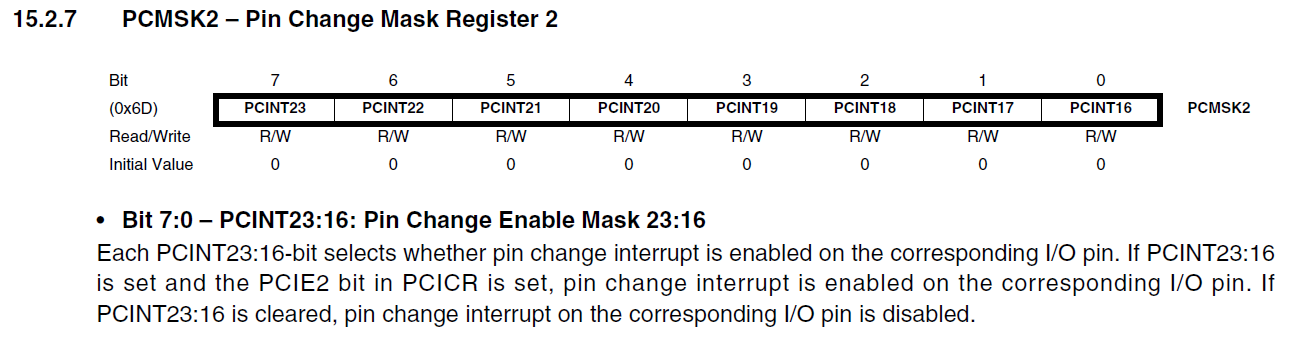
Figure 2: Pin Change Mask Register 2 Description
Again, we only will be wiring encoders to PCINT 16:21 so we will need to include the following line of code: [PCMSK2 |= 0x3F;].
STEP 3: Write the ISR
Now that you have configured your interrupt control registers and decided which pins are going to actively set the ISR all that is left is to tell the computer what to do when it reaches this state. Any time you ever write an ISR you should keep it as short as possible and when declaring variables make sure to make them of type volatile so it is never optimized. To define the ISR just include the following:
ISR(PCINT2_vect){} // Port K, PCINT16-PCINT23.
Finally, you will have something like this:

Figure 3: Pin Change Interrupt Example