Screw-Driver/Spring/2019
Screw-Driver: Evolution of Mechanical Design
Author/s: Christian Pla
Introduction
For the design and build of the rapid prototype, figure 1, we took this opportunity to learn for ourselves how screw propelled vehicles operate under various conditions. After designing the 3D model of the prototype, gathering metal parts, researching for appropriate DC motors, programming its microcontroller, (Arduino Leonardo) and configuring the Arxterra App over the course of roughly 3 weeks, we assembled the initial robot and tested it for the very first time on a smooth tabletop.
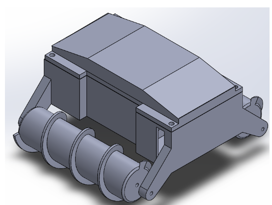
figure 1
Rapid Prototype
The first lesson that we learned immediately upon testing the robot for the first time was the fact that one of the propelling screw was threaded in the wrong direction. We knew this after attempting to drive the robot forward on a course surface, with the robot unfortunately staying in place. For screw propulsion to work, one screw must therefore be threaded clockwise, and the other counter-clockwise as shown in figure 2. The technical matters for this figure are discussed in our “Physics of Screw Propulsion” blog post. For the robot to propel forward, the screws must also rotate in opposite directions. The force vectors in the figure illustrates the physics of this process. In our haste, both screws were threaded clockwise in Solidworks assuming that they can be orientated the correct way during assembly. Another screw therefore had to be redesigned and printed. The physical build of the rapid prototype is shown in figure 3. Dimensions: 9 x 11 x 4 inches.
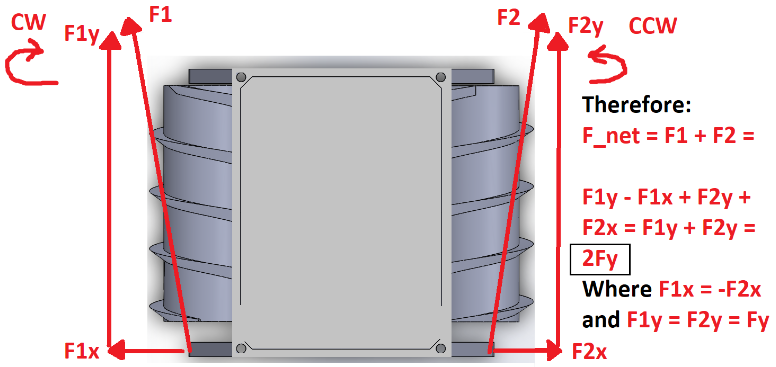
figure 2
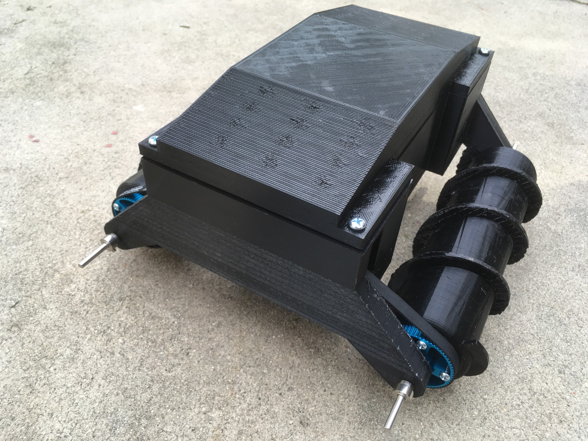
figure 3
Further testing of the rapid prototype suggested to us that the robot was also heavier than necessary, which was an obvious impedance to its motion. The plastic chassis was thicker than necessary and also too large relative to the screws. Furthermore, the threadings on the screws should have had a triangular cross section instead of a rectangular one. Thus the screws on our prototype showed more resemblance to a bolt, rather than a screw. This decision was justified by our observations of the apparent difficulty of the screws driving through the dirt as we controlled the robot. The robot should have had an easier time propelling itself though the substrate than what we saw.
Final Design
For the final design, we were required to have the size of the robot constrained by the size of the 3DOT board. More specifically, we were required to have the electronics housing of the robot to be of roughly the same dimensions as the 3DOT board. This would of course require us to have a final design significantly smaller than the prototype. We however, had to increase the volume of the enclosure slightly more than would be required to enclose the 3DOT board in order to accomodate our two 6V DC motors driving the screws. Thus, we are also using much smaller motors for the final design in proportion to the smaller size of the robot. As for the geometry of the driving screws themselves, improvements were also made. The cross sections for the screw threadings were made triangular, rather than rectangular. This should give the robot better traction in outdoor loosely packed terrain such as dirt or sand than what was observed with our rapid prototype. The Solid Works 3D model of the final design is shown in figure 4. We do not yet have a physical build, but we should have it shortly after the plastic parts are done printing. We sent to the printers two prepared STL files, one for the chassis, and one for the screws as seen in figures 5 and 6. All plastic parts will be printed from ABS, however, the screws and chassis will be of different color. To simplify assembly, all holes were sized to accommodate only M2 nuts and bolts. Furthermore, you may see from figure 5 that a rail was implemented specifically for the 3DOT board to slide into for easy installation.
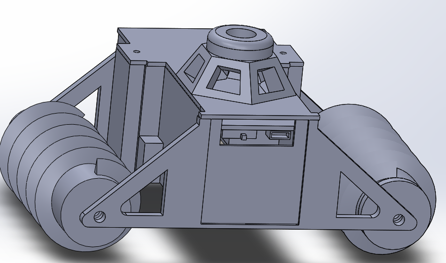
figure 4
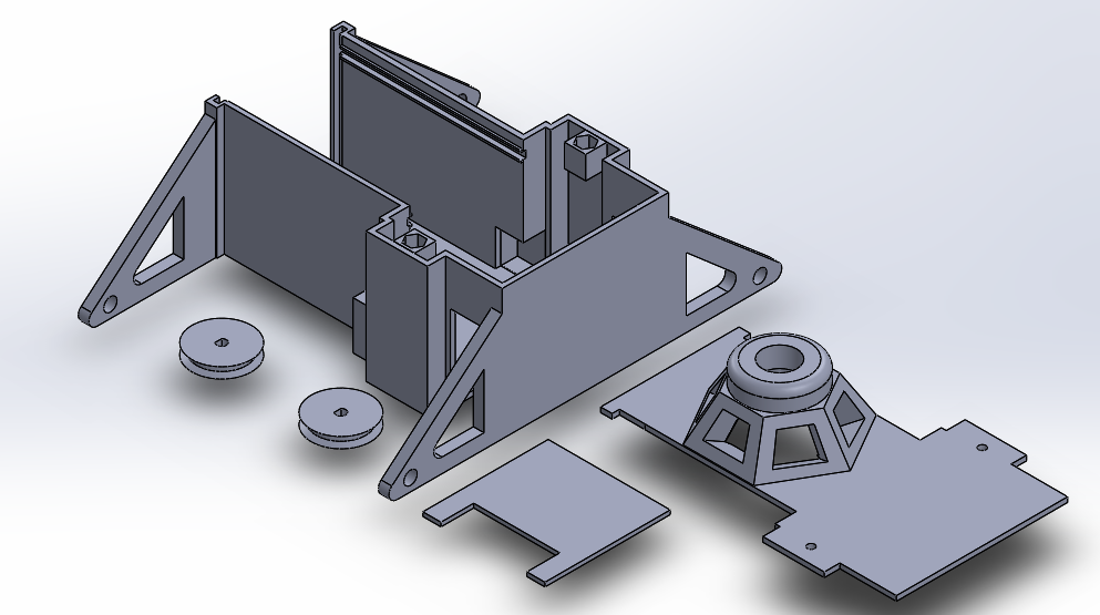
figure 5
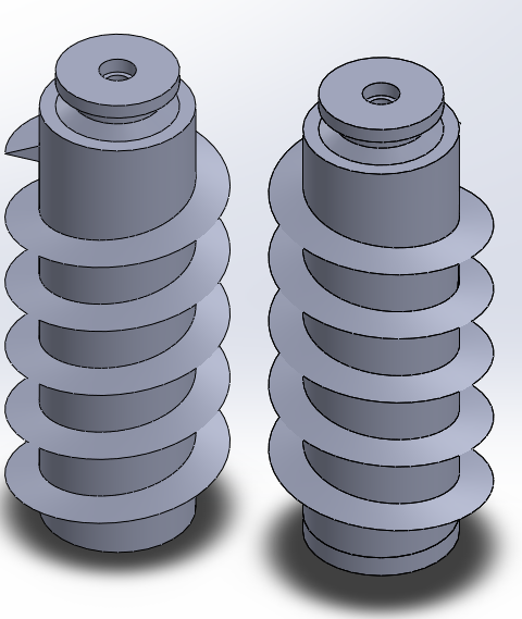
figure 6
Lastly, for the drive system we will use a belt and pulley system with a 1:1 ratio. This was also changed from the rapid prototype, where we used gear pulleys and timing belts. The belts here however will be stretchable rubber round belts. The two pulleys to be mounted on the motor shafts are also seen in figure 5. And as you can see in figure 6, the other two pulleys are directly built into the screws. In figure 4, you can also see a cupola mounted on the top of the robot, added for purely aesthetic purposes at request of the customer. Figures 7 and 8 shown more perspectives of the design. Notice the 3DOT board and motors are modeled as well.
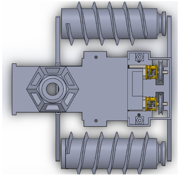
figure 7
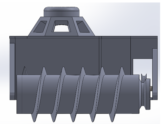
figure 8

Figure 9

Figure 10

Figure 11
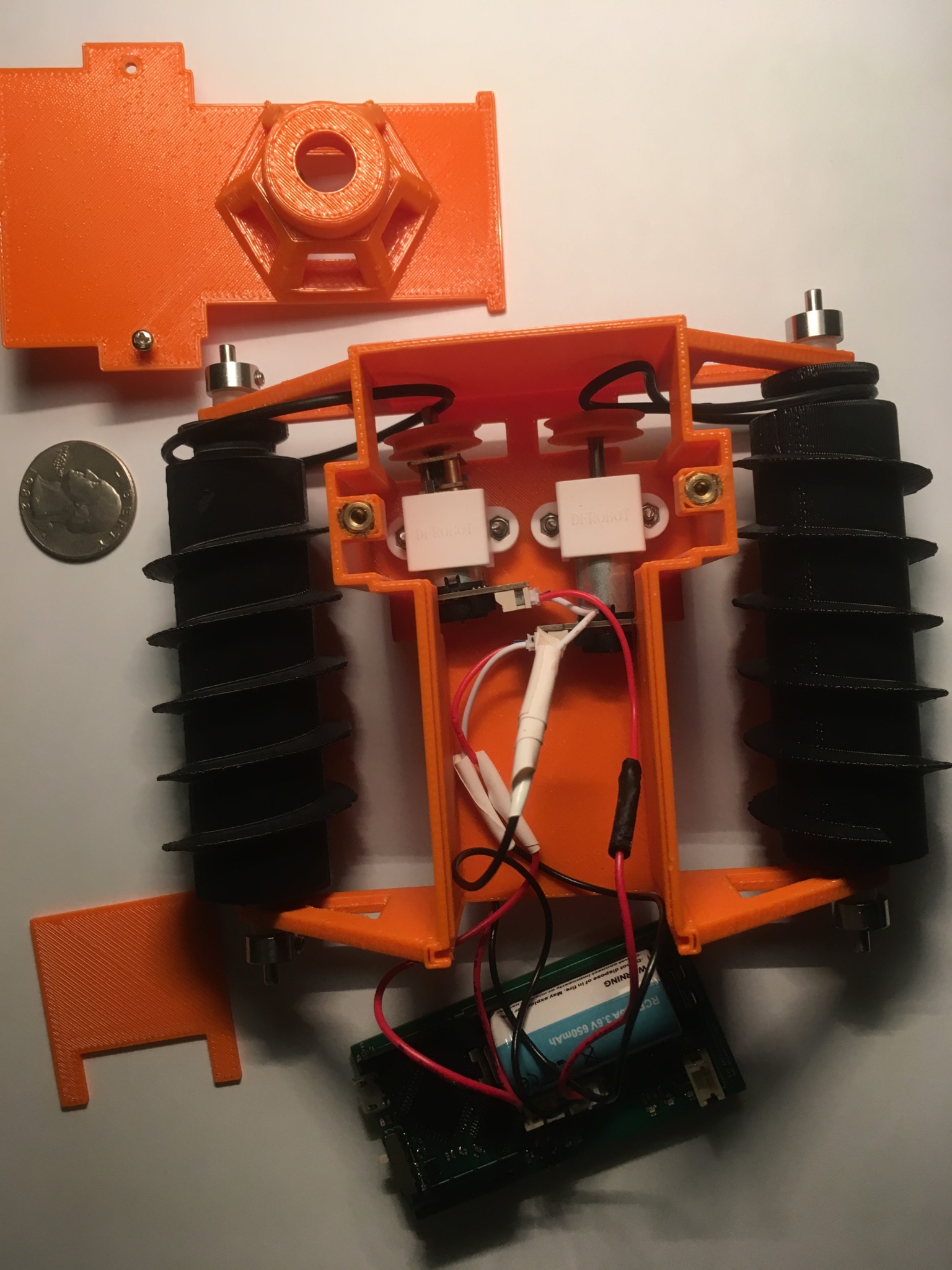
Figure 12
Final Design Estimated Print Cost, Time, and Specifications
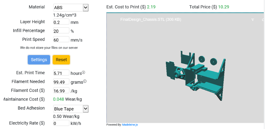

figure 9
Chassis:
Estimated Cost: $10.29
Estimated ABS Filament Needed: 99.49 grams
Screws:
Estimated Cost: $9.77
Estimated ABS Filament Needed: 68.83 grams
Complete Design:
Total Estimated Cost: $20.06
Total Mass: 0.168 kg
Total Estimated Print Time: 10.57 hours
Final Robot Dimensions: 3.79 x 5.72 x 2.97 inches
Mechanical Calculations: Derived Speed and Torque Formulas
Speed Calculations
The speed and torque calculations here assume that we are using a belt-drive system (see fig. 1) to drive the screws consisting of two independent motors with a pulley on each motor shaft, and a pulley mounted on each screw. The diameters of the motor shaft pulleys and the diameters of the screw mounted pulleys can be of different values. For example, a motor shaft pulley that has twice the diameter of the screw mounted pulley will enable the screw to rotate at twice the rate of the motor speed. While for this same situation, the torque on the screw will be halved the amount of the torque on the motor.

Figure 1. Taken from: https://tech.txdi.org/gearsandpulleys
Now lets start with the speed calculations. Assuming we have a driving pulley of diameter dm (mounted on the motor shaft) and a driven pulley of diameter dp (mounted on the screw) we already know from basic physics that the speed relationship is:
wp = (dm /dp)wm
Where wp is the angular speed of the of the screw and wm is the angular speed of the motor. The speed of the motor is given in your datasheet. Now with this relationship we can first deduce the theoretical forward speed of the screw-driven robot. Assuming the length between threads on the screws, the pitch, is equal to p, we can easily picture that with each 360 degree rotation of the screw, the screw may move forward through a substrate by distance p. Therefore we can immediately infer that the forward speed of the robot is simply the product of the pitch of the screw and the angular speed of the screw:
sforward = pwp
Now the sideways rolling speed is also easy to derive from quick visualization. Except this time, the screws will function as wheels. We can therefore infer that this speed also depends on the total diameter D of the screws (distance measured from thread to thread, not just the inner cylinder). Thus with each 360 degree rotation of the screw, the robot moves sideways by distance D, or:
srolling = Dwp
Torque Calculations
As with the speed calculations, we start off with a known basic relation from physics. Thus with the pulley system in question the torque relationship is:
p = (dp/dm)m
Where we used the same subscript naming scheme as in the speed section above. Again the motor torque in the above equation be taken from the datasheet of the motor used. This relationship relates the motor torque to the torque on the screw. For our purposes, no other torque related relationships were required for us.
The Basic Physics of the Screw Drive System
After extensive internet research, we eventually found a promising source that outlined the theoretical framework of dual screw propulsion. This source is given in the references below. From this, we learned everything we needed to know in order to produce forward/backward motion.
Firstly, given a screw propelled vehicle with two independent motors, the motors, and therefore also the screws, must rotate in opposite directions: clockwise or counterclockwise. This will provide forward or backward propulsion, depending on the rotation direction of each motor. And obviously if the motors are rotating the same direction, we will have sideways, rolling motion: like a standard wheeled vehicle. Due however to the geometry of the screws, the path of the sideways motion will be a somewhat noticeable arc, depending on how far it rolls.
Based on the research from our source, we redrew their sketch of the force vector diagram on the screws while the vehicle is driven forward seen in fig. 1. As you can see, the rotation of the screws produces forces at roughly 60 degrees from the horizontal, symmetric about the vertical. From the decomposition of the vector components, you can see that the horizontal force components cancel out yielding a net forward force.
Figure 1
Another feature of the geometry of the screws that you must consider is the way that they are threaded. Screw propulsion may only work if the screws are threaded in opposite directions during 3D modeling. As you can see in fig. 1 the winding directions of the screws are symmetric about the vertical. In Solid Works, to produce the screws, we first produced a cylinder, then sketched an isosceles triangle profile on the cylinder, and lastly swept the profile about a helix. For the rapid prototype, we hastily produced poorly designed rectangular profile that did not fair well driving through dirt and sand. For one screw, the helix is clockwise, and for the other, the helix is counterclockwise. During the design of our rapid prototype, we also mistakenly threaded both screws the same direction assuming they can be orientated as you can see above. A third screw therefore had to be later printed after realizing this.
References
1. https://www.researchgate.net/publication/273769135_Small_Remotely_Operated_Screw-Propelled_Vehicle