Introduction
The space environment is different from that inside Earth’s atmosphere. When we (humanity) send electronics into space — satellites, space stations, whatever the case may be — they are subject to a phenomenon called “charging,” whereby charged particles build up on or inside them. Since spacecraft charging can potentially compromise the integrity of our components (they operate on controlling charge flow, after all … uncontrollable charge buildup might throw a wrench into that operation), it is important that we understand its causes and ultimately how to mitigate its effects.
The CubeSat Club (Club) at California State University, Long Beach (CSULB) intends to tackle this problem by “develop[ing] design requirements for a 3U[-sized] cube satellite capable of measuring the space environment in geosynchronous Earth orbit [(GEO)],” “in correspondence with…Dr. Henry B. Garrett [of JPL].” For several semesters, the SPARCCS project in EE 400D (a class at CSULB) has contributed to this end goal in small steps. In particular, last semester’s group finalized designs for a 3U chassis and began preliminary work on a sensor board.
The primary objective of this project will be continuing last semester’s work and developing an appropriately-sized dosimeter equipped with an electromagnetic interference (EMI) sensor.
Source Material
- Vuono, Nick (Fall 2015). “SPARCCS Project Level 1 Requirements.” Arxterra Blog Post.
- Benton, E. R. and E. V. Benton (Sept. 2001). “Space radiation dosimetry in low-Earth orbit and beyond.” Nuclear Instruments and Methods in Physics Research Section B: Beam Interactions with Materials and Atoms 184, 255-294.
- Vuono, Nick (Fall 2015). “SPARCCS Fall 2015 Summary Blog.” Arxterra Blog Post.
- Macias, Zacharias (Fall 2015). “SPARCCS Electronics Design.” Arxterra Blog Post.
- Vu, Kenneth (Fall 2015). “SPARCCS Mechanical Design.” Arxterra Blog Post.
- Antunes, Sandy. DIY Satellite Platforms: Building a Space-Ready General Base Picosatellite for Any Mission. Maker Press, Project Book, “Space-Ready Systems.” O’Reilly.
- Antunes, Sandy. DIY Instruments for Amateur Space. Maker Press, Project Book, “Put Sensors Into Space.” Maker Media.
Objectives
Unlike many other projects in EE 400D, the SPARCCS project is professionally tied to the Club on campus. All of our funding comes from the Club, as do our Objectives.
This semester, the goal is to develop and ultimately build two instruments on one board: a Geiger-Muller counter, which is a type of dosimeter (measures radiation); and an electromagnetic interference (EMI) monitor. Both must be integrated onto a single printed circuit board (PCB), and this PCB must fit the dimensions of last semester’s (~9 cm by 9 cm). The finished board should weigh no more than ~0.5 kg and consume no more than ~0.5 W of power. The PCB must include a single microcontroller which collects sensor data from both instruments and sends a single packet — in a particular format (to be determined, currently 3.3 V or 5 V logic is expected, along with I2C protocol) — to the satellite’s Command and Data Handling (C&DH) PCB.
Level 1 Requirements
Based on the objectives and informal requirements from the CSULB CubeSat Club (Club), as well as the requirements of last semester’s group, we (the Project Team) propose the following Level 1 Requirements.
- The Project shall by managed by and operated in collaboration with the Club through its Internal Vice President.
- This shall be verified through record of formal correspondence with the Internal Vice President
- The Team shall report on the progress during the Club’s general body meetings through at least one Team representative.
- This shall be verified through formal written record of a Team member’s attendance and reporting.
- The cost of the project shall not exceed $250.00
- This shall be verified through a final, formal budget document at the conclusion of the Project.
- The final product shall fit on a printed circuit board (PCB) of Club-defined size (~9 cm by 9 cm unless changed by Club).
- This shall be verified through physical measurement of the board at the time of formal Project presentation.
- The final product shall implement a Geiger-Muller Counter dosimeter, electromagnetic interference monitor, and microcontroller in a single PCB.
- This shall be verified through final design documentation as well as presentation of the physical product at the time of formal Project presentation.
- The final product shall pass all Club-defined performance tests (to be determined, but including radiation shielding requirements, particular radiation sensitivity, etc.).
- This shall be verified by the Club.
- The above requirements shall be met by Monday, May 09, 2016, the final exam date for EE 400D’s Wednesday section as determined by CSULB.
- This shall be verified by the Instructor of the course.
Further Review and Discussion of Last Semester’s Requirements
The Level 1 Requirements of last semester’s Team (referenced earlier in this post) satisfy all of the criteria in the appropriate rubric explicitly: they are quantifiable, verifiable, and realizable. They include mention of exactly how the requirement is verifiable through a sub-bullet — we also adopt this method. Since our project is different, our technical requirements are different, but the same level of relationship with the Club is maintained throughout.
Since the technical part of the Level 1 requirements is different, the Level 2 requirements of last semester’s Project will not necessarily match up with what ours will be. However, specific requirements such as cable shielding and component shielding requirements will remain the same.
Jeremy Seiden: Systems Engineer Review and Research
- Must consider orbit (geosynchronous Earth orbit) (GEO)
- Considerations for CubeSat
- Cost, Weight, and Power determined by Club
- Bandwidth? Processing? Saturation? Variability?
- Develop dosimeter: sensor for measuring radiation levels
- Consider measurement units
- rad
- Gray (SI unit)
- keV/µm (see Linear Energy Transfer)
- Operational details needed:
- Number of contact passes
- Communications support required
- Approximate required data rate
- Electronics considerations:
- Calibration
- Noise
- Filters/amplifiers?
- Degradation/recalibration
- I2C and Serial Communication Interface
- Cadence/triggering
Linear Energy Transfer (LET)
- Describes action of radiation on matter
- How much energy does a single ion/”piece” of radiation transfer to a material, per unit distance traveled across the material?
- This is dependent on both the radiation and the material
- Typically measured in keV/µm
Sources of Ionizing Radiation
- Galactic cosmic rays
- Earth radiation belts: e- and protons trapped in geomagnetic field
- Solar particle events
- Typical particles include alpha, beta, and gamma
Types of Dosimeters
- Film badge
- Quartz fiber
- Thermoluminescent
- Track detector (nuclear plastic/solid-state)
- Floating gate CMOS (RADFET)
- Sensitivity measured in Hz/rad
- Current converted to frequency
- Very low power
- See Benton and Benton (2001)
- Sensitivity measured in Hz/rad
Proposed Solution
- Multiple RADFET sensors
- This will require independent temperature readings for compensation
- Increase dynamic range
- Allow for detecting radiation due to different particle types
- Storage/packetizing will reduce dependency on a large-bandwidth connection
Chelsea Mediavilla: Electronics Engineer Review and Research
Literature Review
Upon researching previous CubeSat projects, I conclude that the role of Electronics Engineer mainly consists of designing the PCB, sensors, and power source(s) for the satellite. In our case, the Club has provided power supply (a battery connected through USB), so the power source is not an issue.
The Electronics Engineer is also responsible for breadboard simulations and tests. The SPARCCS Spring 2016 Team will focus on the detection of radiation, electromagnetic interference, and, if possible, the inclusion of a timing device.
Sensors
- During previous semesters, SPARCCS teams have implemented accelerometers, pressure sensors, magnetometers, dosimeters, light sensors, etc.
- Dosimeters and electromagnetic interference (EMI) monitors will be necessary for the new design. The others may be irrelevant to the CubeSat’s overall mission and objectives as determined by the Club.
- A light sensor may be used to incorporate a timing device.
- Compact Reconfigurable Environment Assurance Monitor (CREAM) is an all-in-one package which has been used for professional CubeSats.
Printed Circuit Board (PCB)
- PCB design has previously been done via a Fritzing diagram. We will use this diagram to help organize the necessary components and connections on the board.
- PCB layout will be done using LTSpice in Eagle CAD, as it has been done in the past. Practice with these tools has begun.
Power
- Based on the designs of previous projects, CubeSats are traditionally powered with solar cells and batteries. CAMTOA solar panels and high power lithium batteries were used for Fall 2015’s SPARCCS 400D project.
- Since the Spring 2016 Team’s project will be a part of the larger CubeSat design, the Team will not be developing power supply. Instead, the power will come from the Club, and has so far been confirmed to deliver USB power to our board.
Eric Hanna: Manufacturing Engineer Review and Research
Introduction/Background
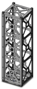
- Based on the previous semesters’ work, the CubeSat will employ a 3U configuration, illustrated below.
- Previous Manufacturing Engineers researched chassis material and manufacturing processes. Because we will be using the same chassis, researching this was not necessary.
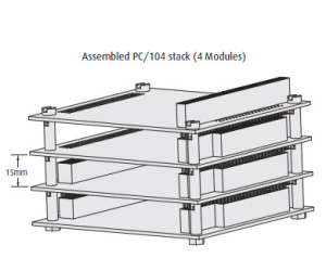
- I instead researched any PCB specifications or requirements for the CubeSat, finding that they typically use a PC/104 form factor, illustrated below.
- Both PCB files and SolidWorks files are available from the previous group. These provide information about the board and chassis dimensions, respectively.
- Tradeoff study still needs to be performed; I will do this to research board houses/suppliers to create our board and verify that it meets any special physical, temporal, or cost-associated requirements.
- I have downloaded Eagle and Solidworks. Training in Solidworks will start first with my Division. Tradeoff study for board house will start with the Division Manager’s supplier recommendation (OSH Park).

Proposed Level 2 Requirements
Based on the operating Level 1 requirements, and on review of last semester’s requirements, I propose the following set of Level 2 requirements.
- The PCB shall be of standardized size according to the direct requirements of the customer (either matching last semester’s board or using a PC/104 specification).
- This shall be verified through physical measurement of the board’s dimensions, as well as design documentation. Note: while at present this is similar to a Level 1 requirement, pending input from the Club will formalize the size and screw-hole placement. This is the natural transition from the existing Level 1 requirement to the Level 2 counterpart.
- The board shall be mounted into a mock-up of the CubeSat with appropriate internal shielding and holes for sensors to take external measurements.
- This shall be verified through physical measurement of the mock-up, as well as visual confirmation by either the Customer or Instructor that the shielding is in place.
Suggestions
- The PCB should be multilayered as needed to accommodate all components in the allotted space. A trade-off study of board houses can be done to determine the best pricing and turnaround for board manufacturing.
- A mock-up should be created as simply as possible, since its purpose is only to aid in the testing of our board and for safer transportation.