Spring 2016 AdBot SolidWorks/3D Model Design
By Muhammad Maqbool (Manufacturing and Design)
Start out with understanding the basic design of AdBot. It consists of a total of eight big wheels, eight tension wheels, four tracks, two gears, one wooden shaft, one wooden pole, one pole holder, and one flat top. The design for the wheels and tracks are from previous semester’s RoSco. I modified them so that they work for AdBot requirements. The tracks are metal in the final design.
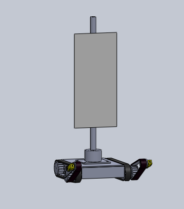
Figure 1. Model front profile.
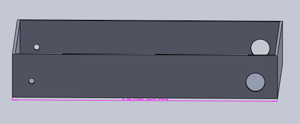
Figure 2. Chassis holes for the motors.
Figure 2 shows the body of AdBot and the dimensions are 12x8x2 inches with a thickness of 0.125 inch. The holes on the back side provide a path for the motor shaft to attach to the wheels directly. The holes have a diameter of 0.160 inch, which was measured using a Vernier caliper.
The diameters of the front side holes are 0.250 inch. They are openings for the shaft, which connects with arms and free-spinning wheels. The shaft has a thickness of 8mm.
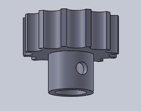
Figure 3. Arm turning gear.
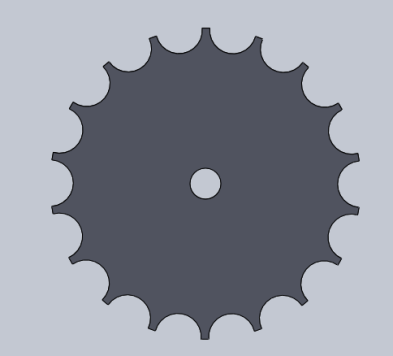
Figure 4. Servo gear.
Figure 3 shows the gear I designed for the shaft. The inner radius is kept to 8.5mm so that it sits on the shaft. I use a setscrew to screw the gear on the shaft to make sure it does not move from its position. Figure 4 shows the gear design for the servo and it is screwed directly on the servo arm. The two gears are kept close to each other so their teeth can overlap. When the gear on the servo moves, it moves the shaft gear with it, hence moving the arms up or down.
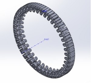
Figure 5. 3D track model.
Tracks are one of the most difficult objects to be printed. The tracks around the arms have a diameter of 4.9 inches. The tracks in the back have a diameter of 9”. To increase the size of the tracks from 4.9” to 9” I increase the circular pattern in the SolidWorks file and then increase the length of the tracks while keeping in mind the gap between each loop, because the gap actually makes the track stretch when it is 3D printed. The problems I faced while printing the tracks was that the 9” tracks has more weight compare to the 4.9” tracks so they hang from the wheel rather than sit tight on the wheels.
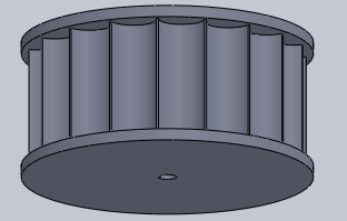
Figure 6. Wheels.
All the wheels on our AdBot have a diameter of 2.5” with a thickness of 0.7”. The two wheels in the back connect directly to the motor shaft with mount couplings. There are four free spinning wheels on the shaft in the front (two wheels on each side) and one wheel on each arm.
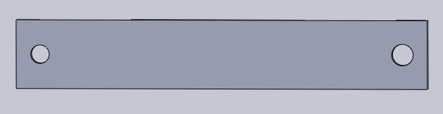
Figure 7. Aluminum arm model.
AdBot comprises two arms, one on each side. The hole in the back is cut so it can fit onto the 8mm shaft and the hole in the front provides path for the motor shaft to connect directly onto the wheel. The arms are made of aluminum. The dimensions I chose are 6×1” with a thickness of 0.125”. I used a drill press to make perfectly aligned holes on the arms.
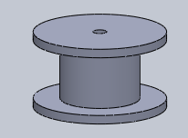
Figure 8. Tension wheels
AdBot has eight total tension wheels. The purpose of tension wheels is to make sure the tracks do not slide off the wheels as experienced by RoSco. The diameter of the wheel is set to 1.5” so it could weigh less and I kept an empty space in between so the tracks can sit on it perfectly.
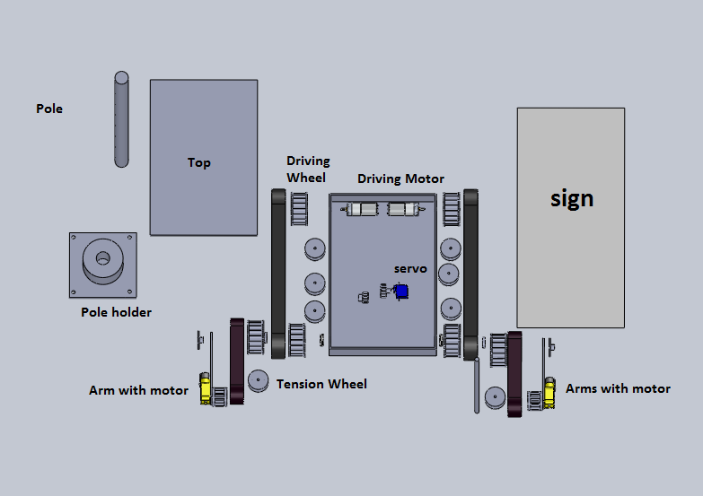
Figure 9. Exploded view of AdBot components.
Conclusion:
The most difficult part for the 3D design in SolidWorks was the tracks. The design was complex and hard to understand. The tracks did not come out as I expected. 3D printing in general is difficult as the parts do not meet your expectations.