Spring 2016 Pathfinder: Project Summary
By:
Peiyuan Xu (Project Manager)
Approved by Peiyuan Xu (Project Manager)
Approved by Xiong Lee (System Engineer)
Table of Contents
Executive Summary
Project Objectives
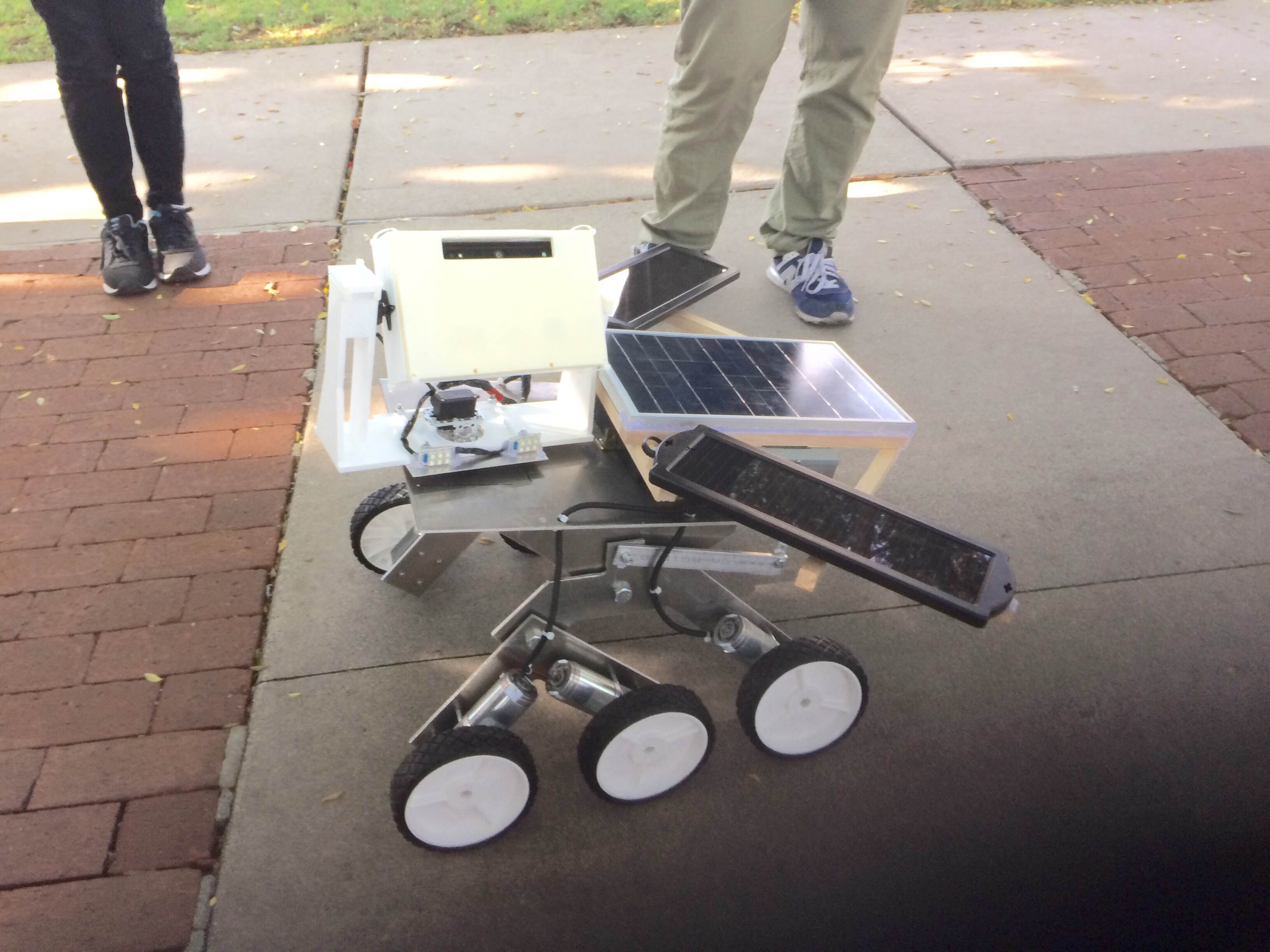
The spring 2016 Pathfinder Rover was inspired by NASA’s MARs Exploration Rover-“Sojourner”. The profile for this semester’s project is to imitate the design of “Sojourner” Rover to prototype a new generation of Pathfinder Rover that implements the Rocker Bogie Suspension System as well as being self-sufficient by using solar panels. The Pathfinder is allowed to have the solar panels charging the battery for up to 8 hours during the day time. Then the customer can spend up to 4 hours at night walking and exploring with the Pathfinder. Ultimately, The customer can use Arxterra control panel on the PC to navigate the Rover by using the cursor to click a point on the map. This generation of Pathfinder Rover is also designed to test and implement SLAM (Simultaneous Localization and Mapping) technology for autonomous vehicles.
Mission Profile:
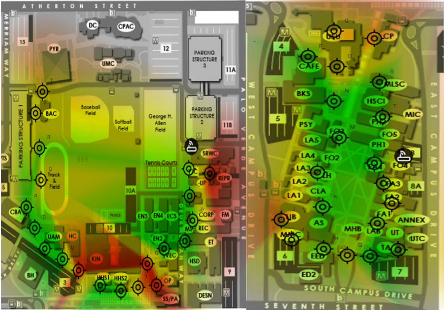
![]() Figure 1 – CSULB WiFi Strength map
Figure 1 – CSULB WiFi Strength map
Since our Pathfinder Rover will be tested at the entire CSULB campus. We need to find out where there is the best Wi-Fi signal in order to gain the stable video stream from the android phone to the Arxterra. The system engineer Xiong Lee was able to use an android App called Wi-Fi Maximiser to map out the Wi-Fi signal strength around CSULB campus. Based on the strength of the Wi-Fi signal, our mission will be narrowed down to the area covered with green on the map. We suggest the customer not to go through the area covered with red because there might be some packet loss and signal lag around the area. We also think this Wi-Fi signal strength map can be useful for other EE 400D project in which case they need to explore the CSULB campus as well.
The changes that made to the Mission Profile and Project Objective can be found here:
Spring 2016 Pathfinder: Mission Profile and Project Objective Update
Design
Figure 2 – 3D Model
The image above is the 3D illustration in SolidWorks that shows the overall design of the pathfinder.
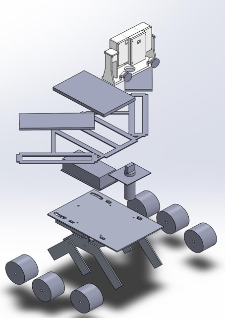
Figure 3 – Exploded Model
This image above gives the exploded view of the Project design. On the top is the Tilt system with the encasement for Google Tango tablet and Android Phone. Below that are the 3 solar panels with resemble the shape of the Arxterra logo. Then there is a metal box to protect all the electronic components. Following that is our new chassis with Rocker Bogie System.
For more details on the structures of this design, refer to:
Spring 2016 Pathfinder Design and Manufacturing – Rocker Bogie Suspension System Design
Spring 2016 Pathfinder Design and Manufacturing – Tilt System Finalized Design
Project Features:
Rocker Bogie Suspension System
- Designed for superior vehicle stability on the uneven surface
- Obstacle-Climbing Capability
- High-clearance chassis
- Slow-speed application
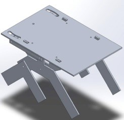
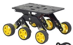 Figure 4 – Rocker Bogie System
New Tilt system for Tango tablet and Android Phone
- Has two servos. One controls Pan system, one controls Tilt system
- Allow stream video from Android Phone correlates with Point Cloud data in Google Tango tablet
- Protect the phone and Tango tablet

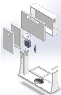 Figure 5 – Tilt System
Solar Panels
- Self-sufficient
- Use three pieces of solar panels to resemble the Arxterra logo
 Figure 6 – Solar Panels
SLAM (Project Tango Modules)
Access to the Point Cloud Data (send data out via Tango Bluetooth API)
Use Depth perception and IMU sensors to navigate Pathfinder go where the user wants to go (Developing)
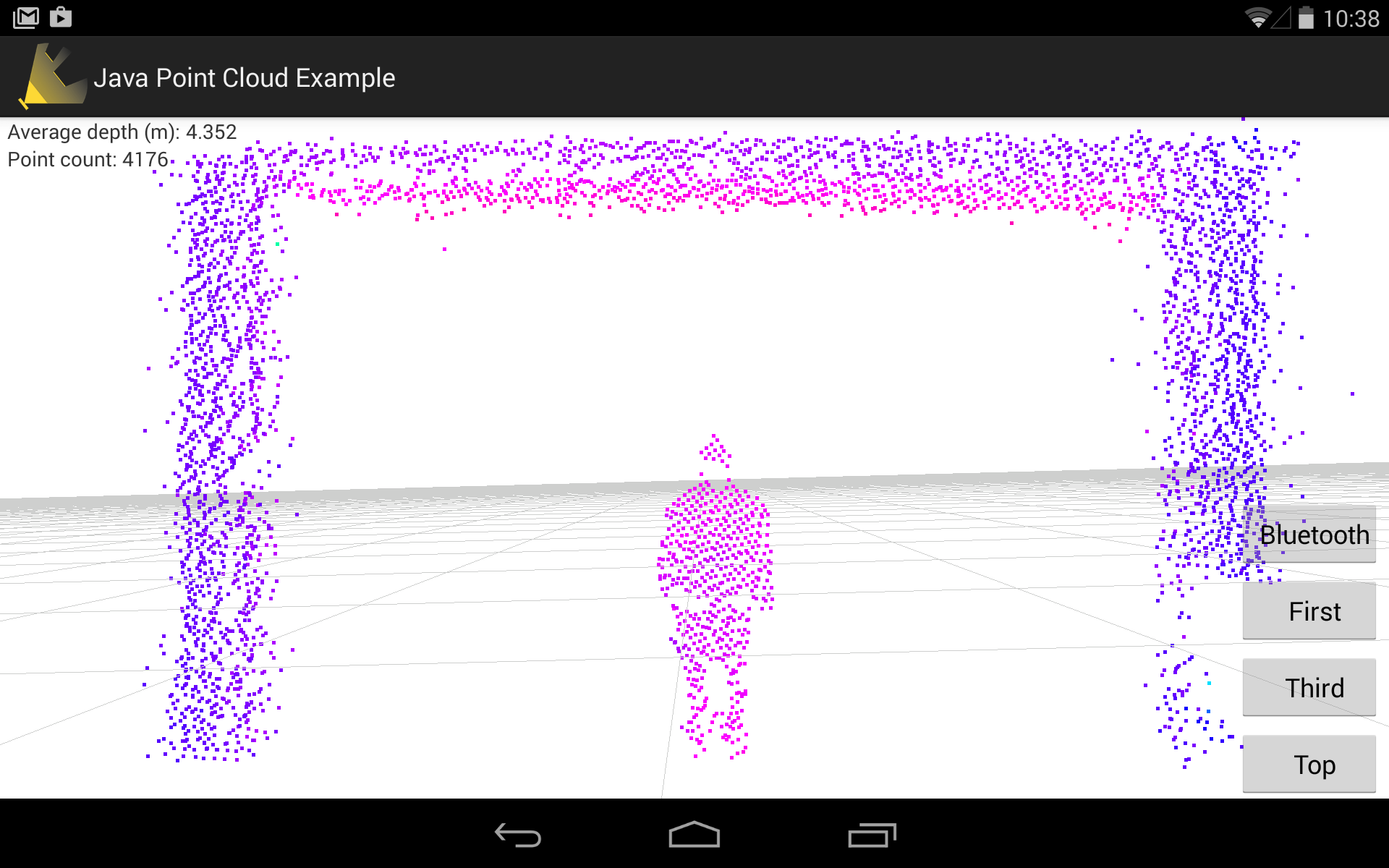 Figure 7 – Point Cloud App
System Design
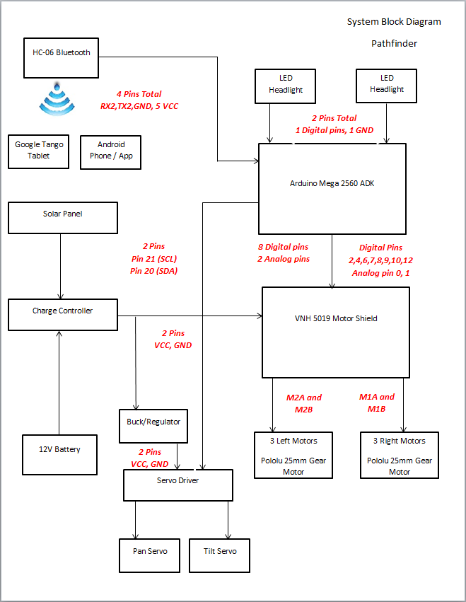 Figure 8 – System Block Diagram
The system block diagram above shows how all of the components interface with each other. First, transmission of data from an android phone or the Arxterra control panel via HC-06 Bluetooth module will tell the Arduino Mega what to do. The Arduino Mega will interpret this data and send it out through the motor shield or servo driver to drive the pathfinders movement. The system block diagram also depicts how the charge controller will interface the power supply and the solar panels to the VHN5019 Motor shield that will drive the pathfinder.
For more information about the system design, refer to:
Spring 2016 Pathfinder: System Block Diagram & Interface Matrix
Experimental Results:
Current Drawn By Motors
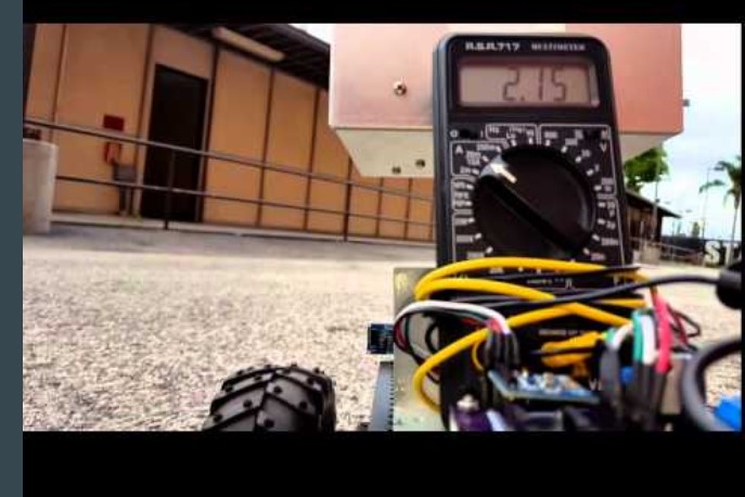 Figure 9 – Current Drawn Test
The purpose of this test is to find the current drawn by the motors on different terrains and in different driving modes (Braking abruptly, Rotating (Under High Stress) and Running forward/backward (Normal Driving) . This test is crucial for us to gain the discharging time of the batteries in order to meet the Level 1 requirement of constantly running for 4 hours.
For Project Level 1 requirements, refer to:
http://arxterra.com/spring-2016-pathfinder-preliminary-project-plan/
Results:
Peak current: 4.8 A (Under highest stress)
-Ex. braking abruptly, rotating, etc
Average current: 1.2 A (Normal driving)
Theoretical discharge time:
20 Ah / 4.8 A = 4.16 hours (high stress)
20 Ah/ 1.5 A = 13.33 hours (normal driving)
Actual Discharge time to 50% : 6.5 hours
This test is conducted for the Wild Thumper chassis
Video Demo
For more information about this current drawn test, refer to:
Spring 2016 Pathfinder: Current Drawn Test
Charging Batteries Using Solar Panels
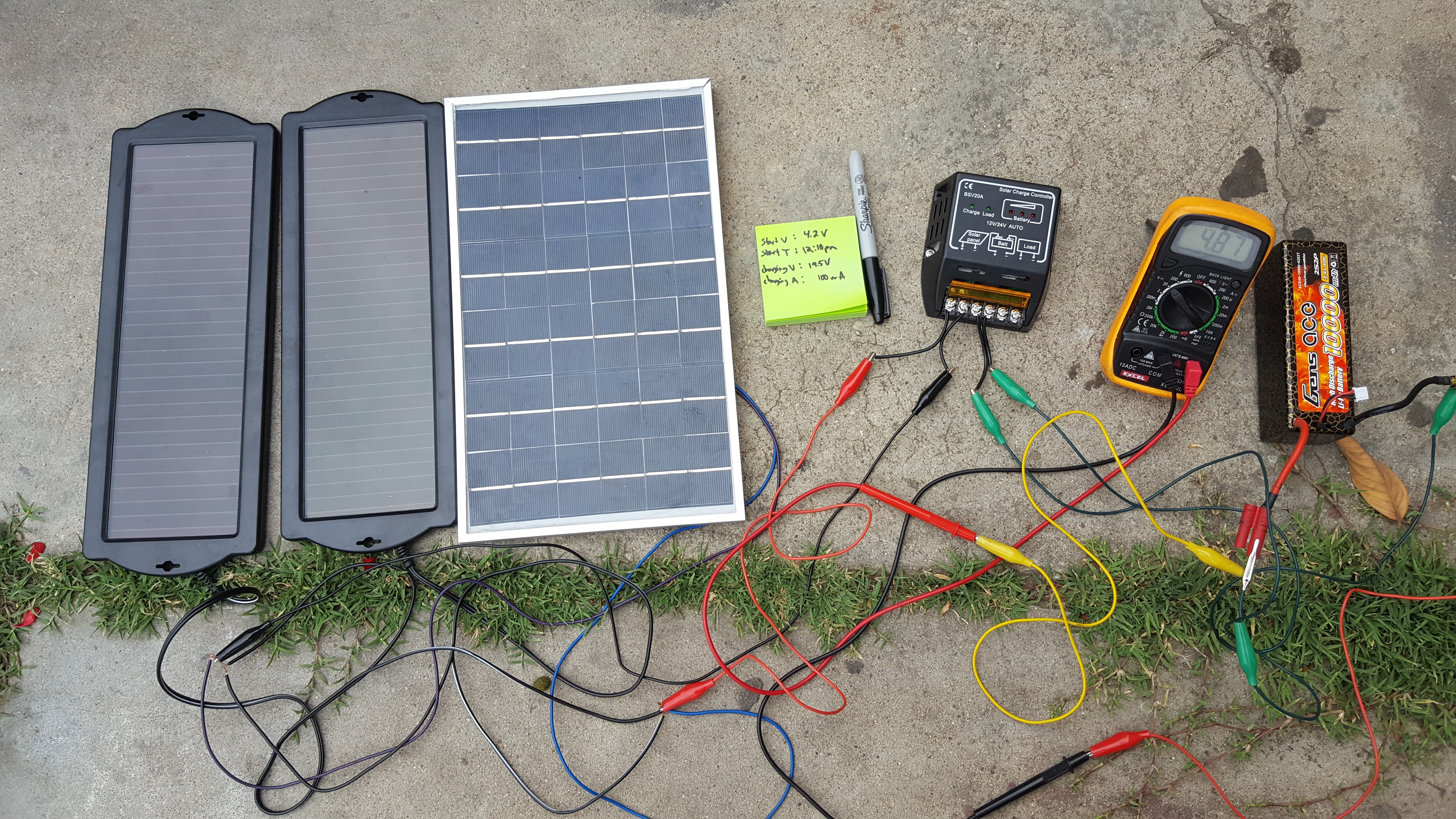 Figure 10 – Solar Panels charging the batteries
The project objective stated that the pathfinder needs to be self-sufficient by using solar panels. This test is to measure the total current the solar panels can supply at direct sunlight. In reality, the charging capability of solar panels will vary depends on the weather condition, therefore, we include some of the other tests for comparison of the worst case scenario.
Results:
-Direct sunlight: 850 – 950 mA
-Shady area: 500 – 750 mA
-Rain or cloudy: 100 – 300 mA
- Important note (current supply by the solar panel determine the time required to charge the battery )
- After charging these batteries in direct sunlight for 8 hours, the voltage level of the batteries increased from 4.0 V to 6.5V which is from 54% to 87%.
- This would meet our Level 1 requirement since it takes around 6 hours of normal conditions run time to deplete our batteries from 7.4 V to 3.4 V.
For more information on how we implement solar panels, refer to:
Spring 2016 Pathfinder Solar Panels Implementation
Project Tango Modules
Figure 11 – Project Tango: Point Cloud
This spring 2016 Pathfinder project used Google’s Project Tango as a platform to test and implement SLAM (Simultaneous Localization and Mapping) technology for autonomous vehicles. Project Tango uses computer vision to give device the ability to know the position in the relative 3D space as well as the distance from the surrounding objects to the device itself.
For more research work of the Project Tango, refer to:
Spring 2016 Pathfinder: Project Tango Preliminary Research
For more details of the project Tango modules our team accomplished or attempted, refer to:
Spring 2016 Pathfinder: Project Tango Bluetooth API
Spring 2016 Pathfinder: Project Tango – Interactive Visualization of data from Tango using Paraview
Spring 2016 Pathfinder: Project Tango Module#5 – Android to Arduino Via Bluetooth
Subsystem Design
Interface Definition
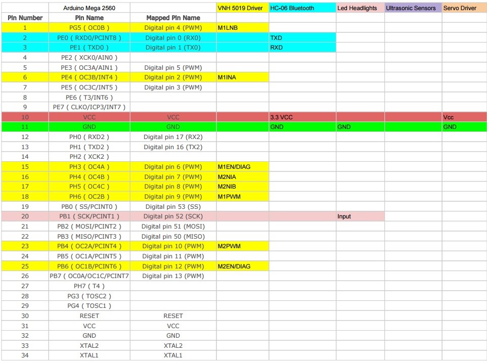
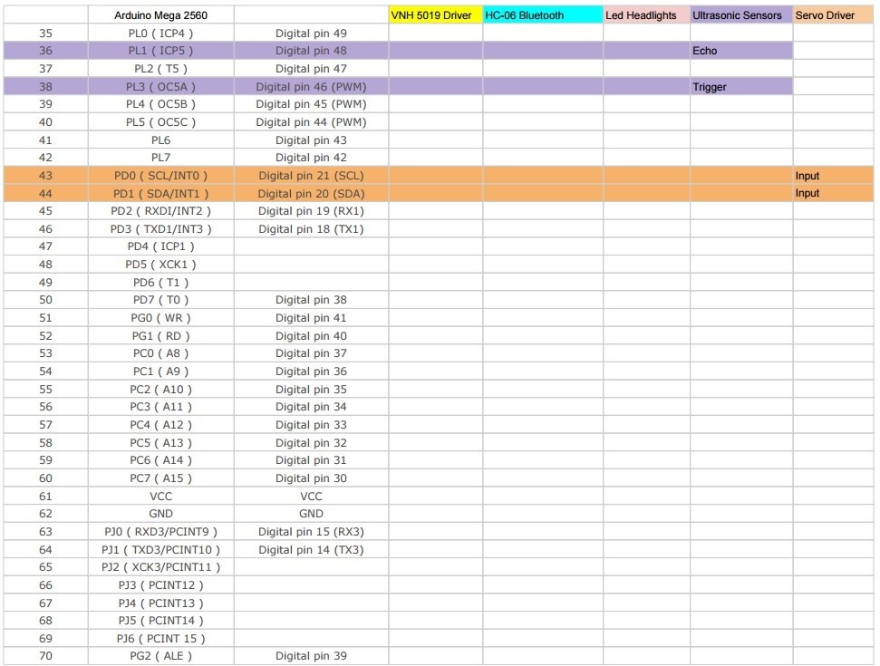
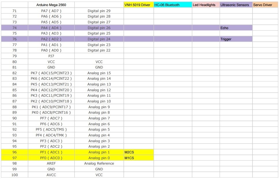 Figure 12 – Interface Matrix
The above interface matrix shows in depth on which pins are used on the Arduino Mega.
For further details on interface matrix, refer to:
Spring 2016 Pathfinder: System Block Diagram & Interface Matrix
One improvement we had after PDR debrief was to highlight the rows and columns with different colors in the interface matrix. Each color represents the corresponding pins used by the component. That makes it a lot easier for us to track the subsystem level pinouts. Also this makes it easy for audience to see during the presentation.
Custom PCB Design
Fritzing Diagram
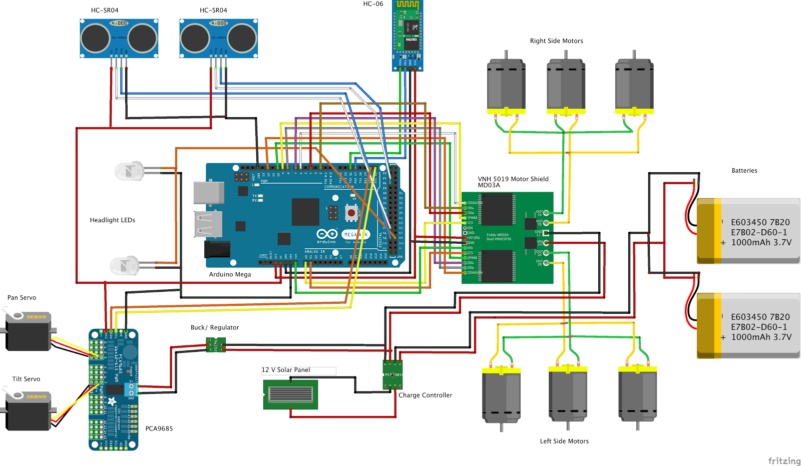 Figure 13 – Fritzing Diagram
Breadboard
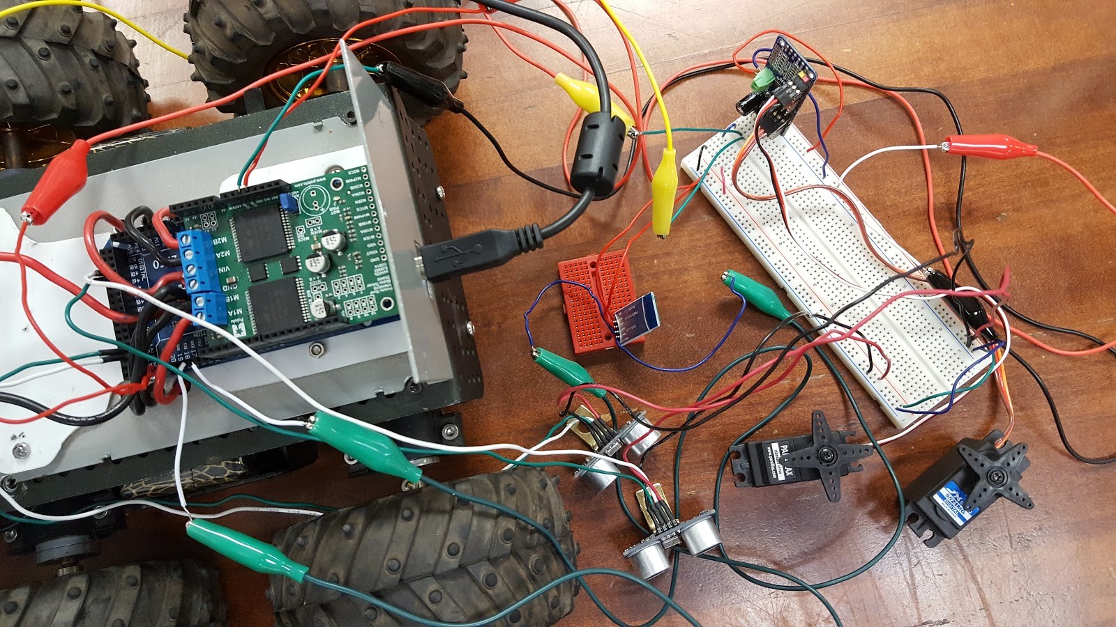 Figure 14 – Breadboard
PCB Schematic
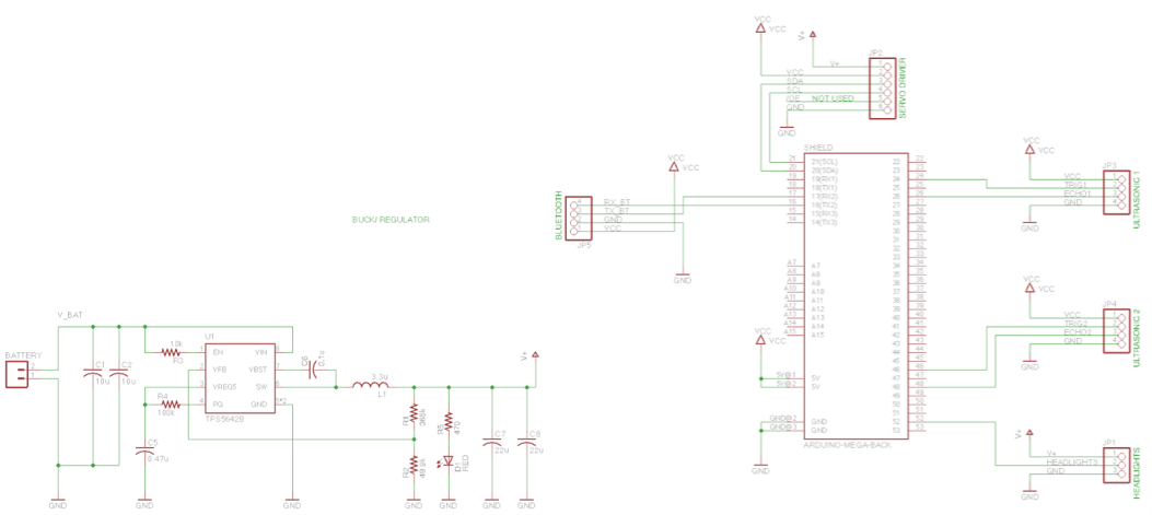 Figure 15 – PCB System Schematic
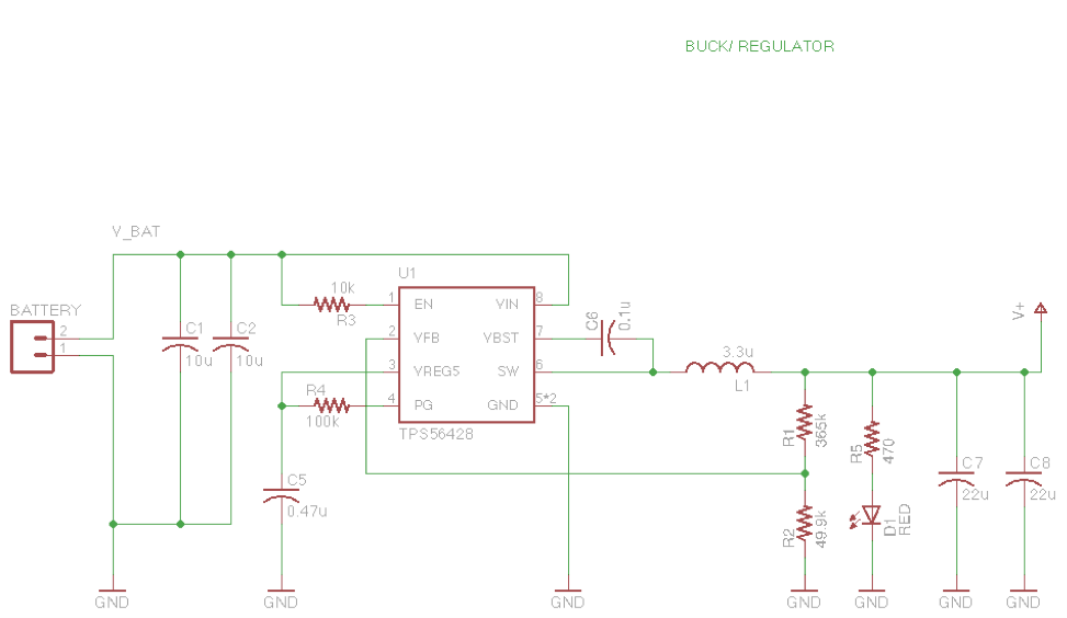 Figure 16 – Buck Regulator
PCB Layout
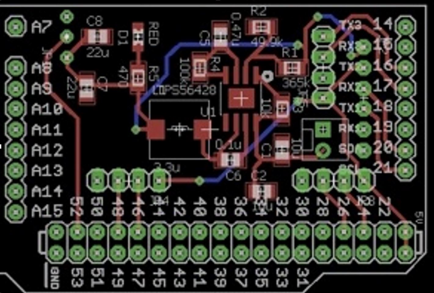 Figure 17 – PCB Layout
The pathfinder project needs a custom PCB to integrate all the electronic components, which included: VNH5019 motor shield, PCA9685 Servo PWM Controller, two servos, six DC motors, HC-06 Bluetooth Module, two HC-SR04 ultrasonic sensors, two LED Headlights. The custom PCB also take advantage of the leftover pins on the Arduino Mega. A buck regulator is required to step down the voltage from 12 V to 5.5 V in order to protect the servo driver. The advantage of using buck regulator over the voltage regulator is to keep a constant current.
For further details about the PCB system schematic design and layout, refer to:
Spring 2016 Pathfinder: PCB System Schematic
Spring 2016 Pathfinder: Design and Manufacturing – PCB Layout
Hardware Design
Overall Design
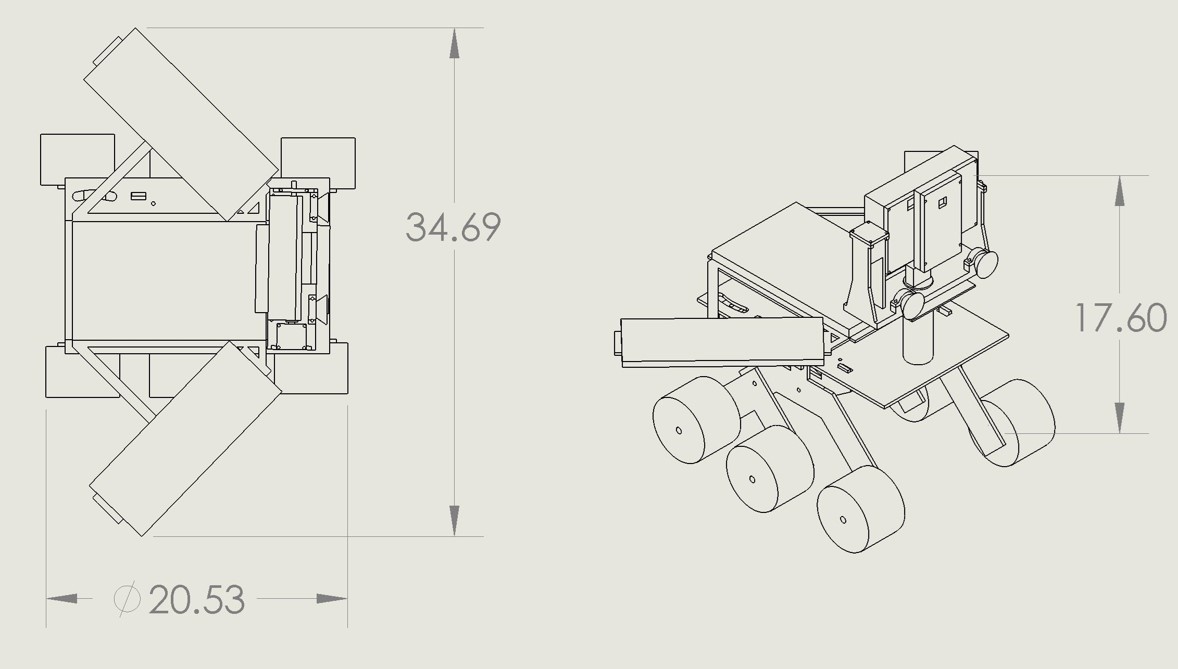 Figure 18 – Pathfinder overall Design
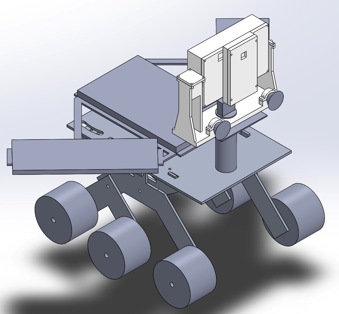 Figure 19 – 3D Illustration
Figure 20 – Exploded View
**Rocker Bogie System**
Figure 21 – Rocker Bogie System
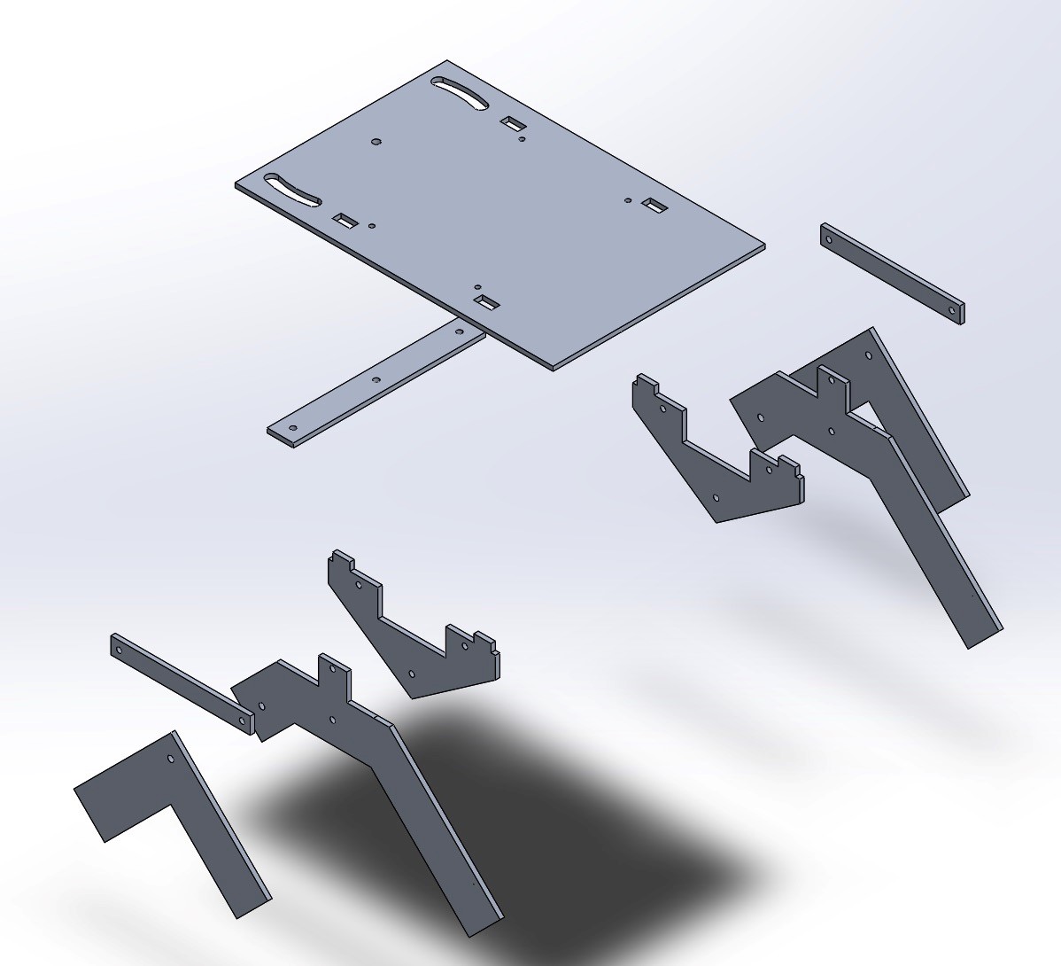 Figure 22 – Exploded View
**Tilt System**
Figure 23 – Tilt System
Figure 24 – Exploded View
These above pictures demonstrate the hardware design from the overall 3D models to breakdowns parts of the pathfinder rover design.
The goal of Spring 2016’s Pathfinder is to hold a Google Tango tablet, phone, solar panels in the shape of the Arxterra logo, a tilt system, and an electronic box. To best traverse obstacles, a rocker bogie suspension system design was chosen, with a top surface area of 12in x 18in. Modeled after ServoCity’s runt rover, the chassis was scaled to meet the surface area required for the above mentioned parts. The tilt system was designed to hold the tablet, phone and tilt servo. Lastly, all parts were modeled on the chassis.
For further details of the hardware design, refer to:
Spring 2016 Pathfinder Design and Manufacturing – Tilt System Design
Spring 2016 Pathfinder Design and Manufacturing – Tilt System Finalized Design
Spring 2016 Pathfinder Design and Manufacturing – Rocker Bogie Suspension System Design
Software Design
Software System Block Diagram
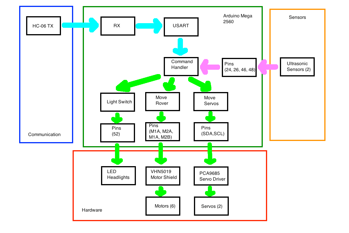 Figure 25 – Software System Block Diagram
The software design follows the system block diagram and focus on the subsystem level software modules development.
For further details on how each software modules works, refer to:
Spring 2016 Pathfinder: Software Design
For reference of Arduino code controlling motors and servos through coolterm, refer to:
Spring 2016 Pathfinder: Software Design
For reference of controlling motors through Arxterra, refer to
Spring 2016 Pathfinder: Bluetooth Communication with the Arxterra App
For reference of controlling servos through Arxterra, refer to
Spring 2016 Pathfinder: Arxterra Servo Control for Pan and Tilt
Verification and Validation Test Plans
Verification and Test Plans are required to prove that the project can meet the L1/L2 requirements.
Since our team received new requirements of building a new pathfinder in a short period of time, many of the verification tests had not yet been done due to the heavy work of manufacturing. The project final demo then was been used for some of the verification and validation tests.
For more details of the verification matrix and Validation Test Plans, refer to the “project resource”
Project Update
Work Breakdown Structure
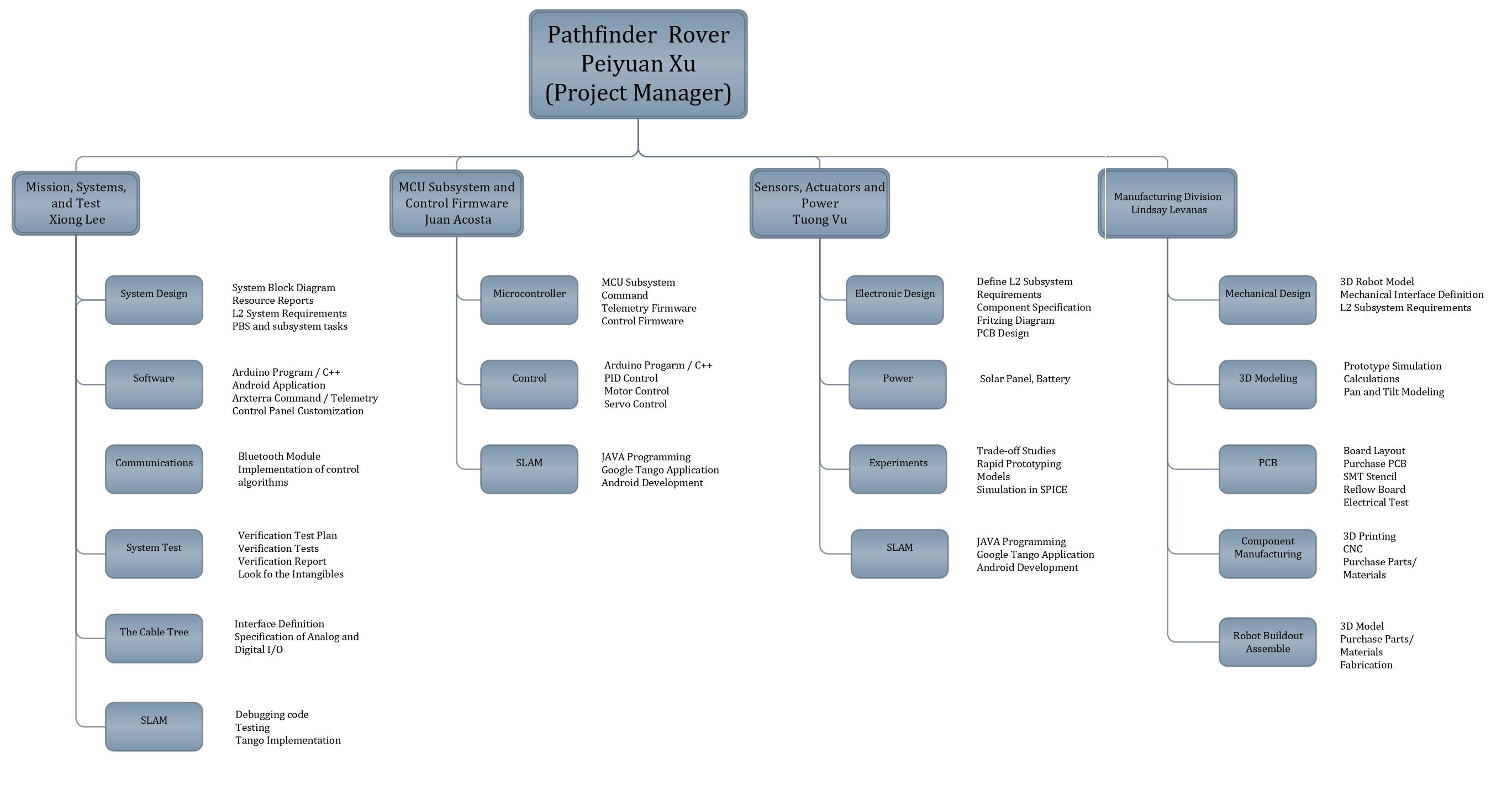 Figure 26 – Work Breakdown Structure
This work breakdown structure demonstrates all the work needed to be done for this project Pathfinder Rover. There are four branches that indicates different job duties and division works assigned to the system and subsystem engineers.
Resource Report
Mass Report & Power report
The mass report and power report are both missing because our team did not have enough time to update the reports for the new pathfinder.
For previous mass report and power report, refer to “CDR presentaion” in Project resource file
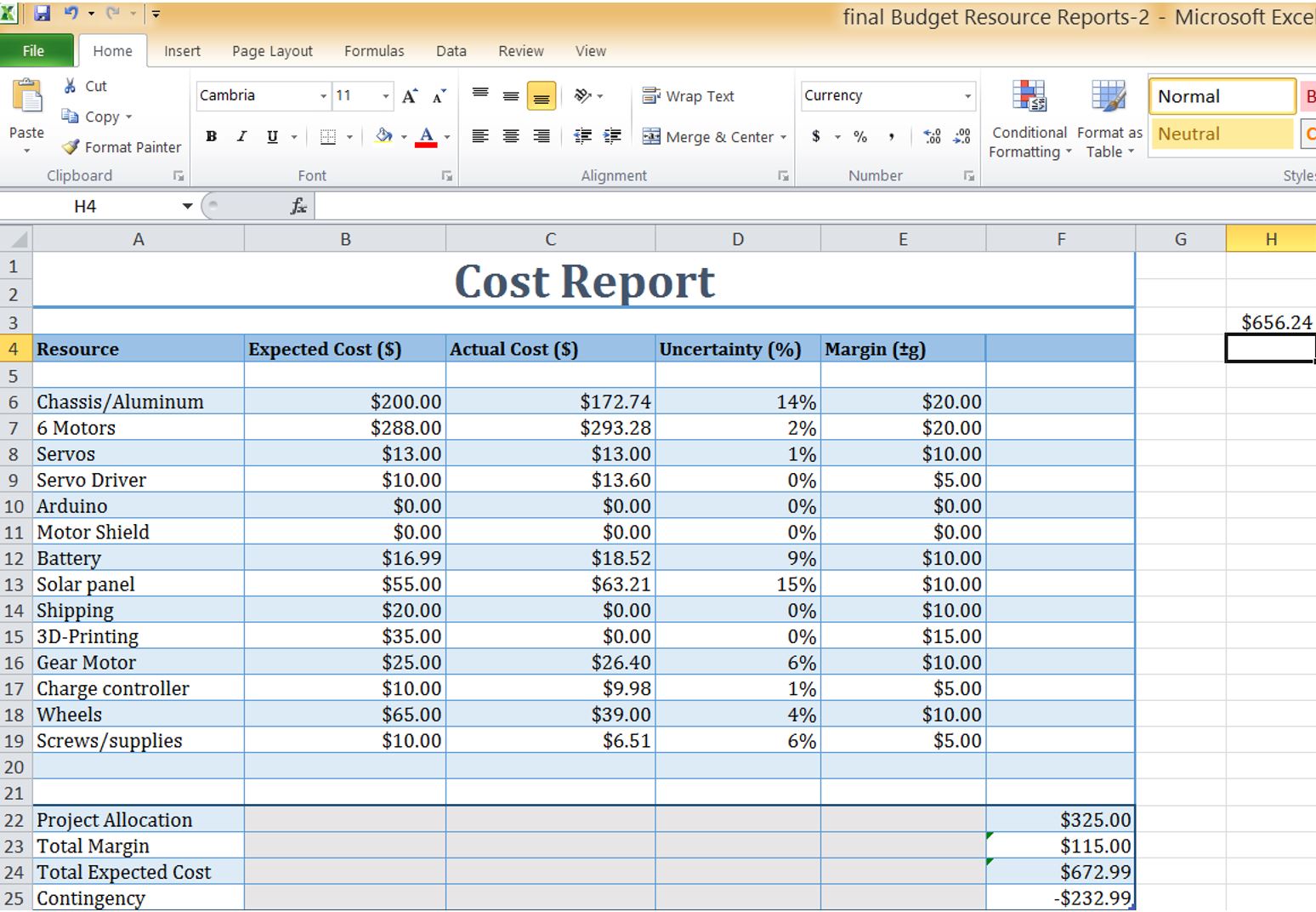
Cost Report
Project Schedule and Progress
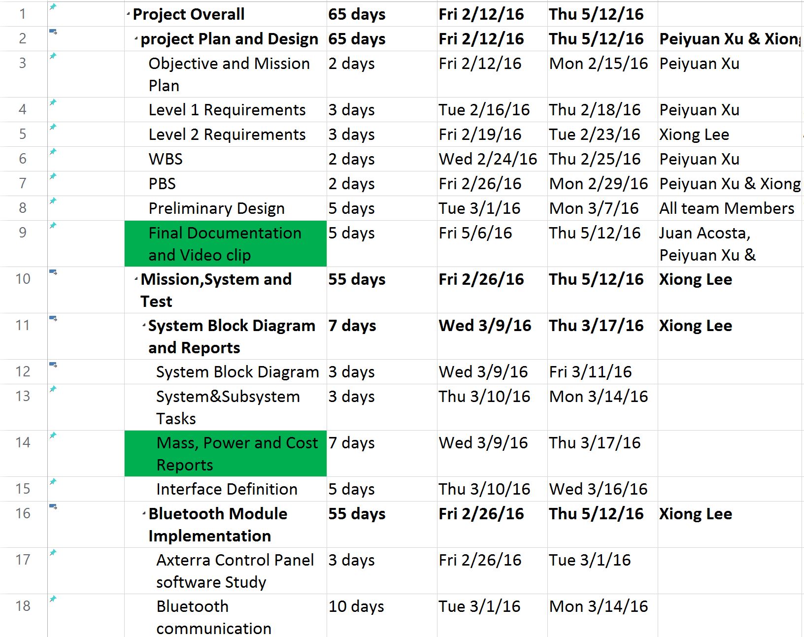
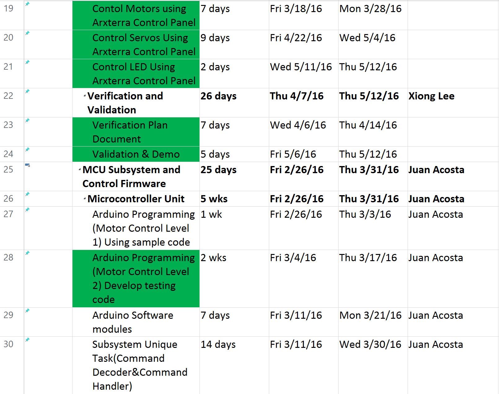

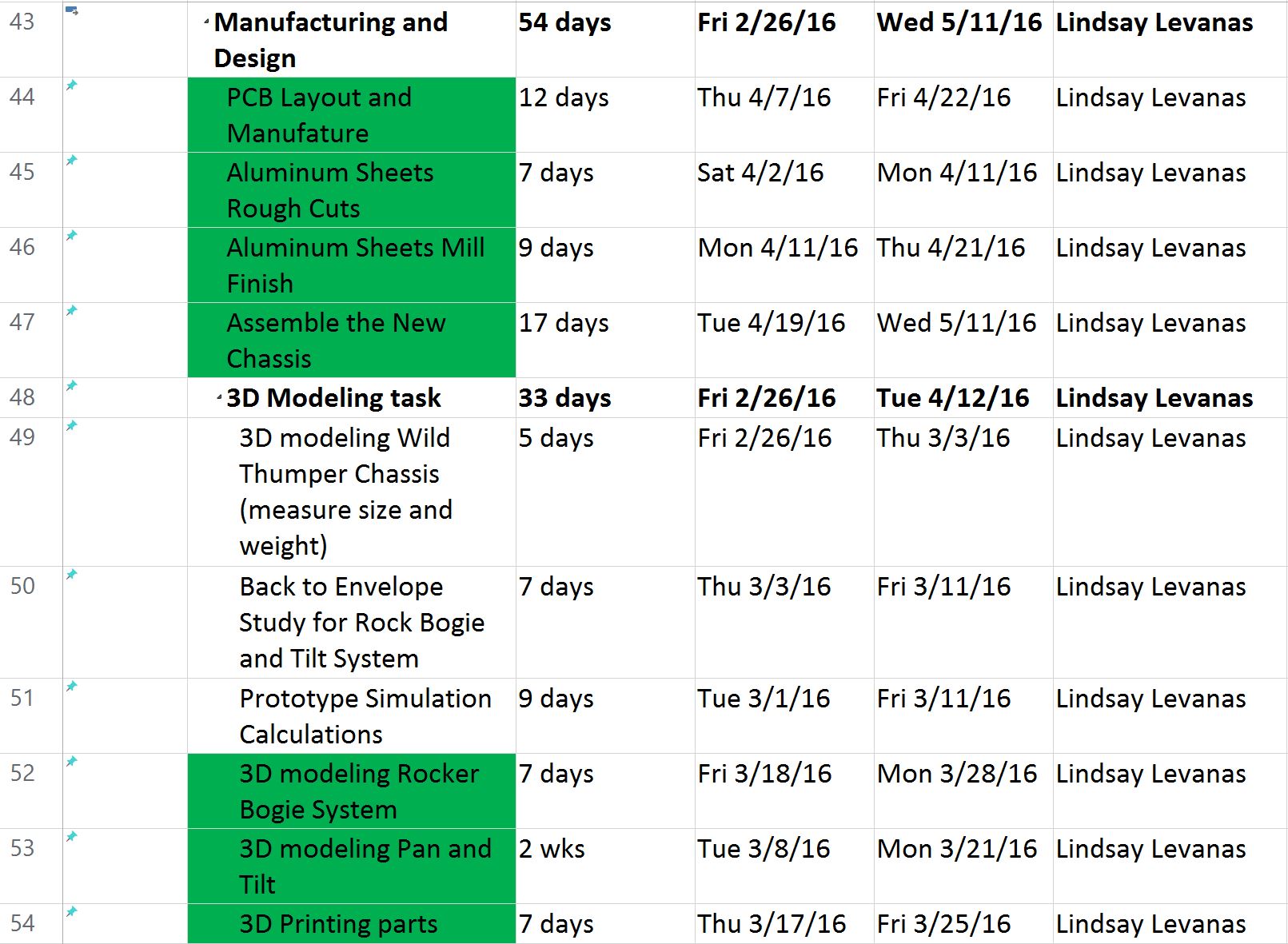
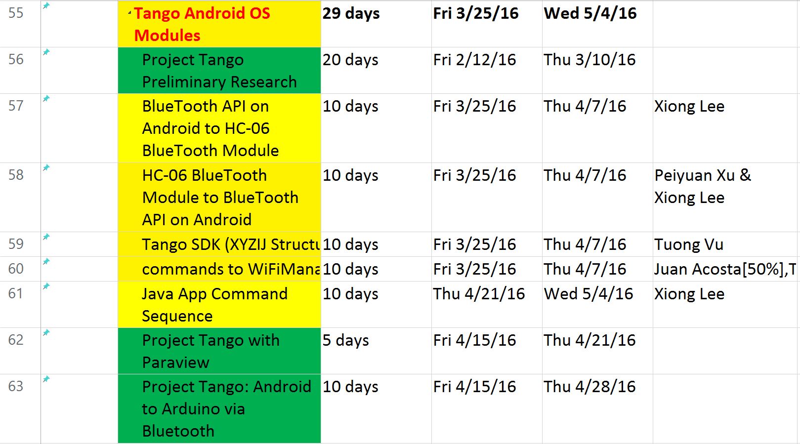
Above is the final schedule for this spring 2016 Pathfinder Rover Project. The Project Overall duration is 65 school days. This schedule was made and managed by the project manager to keep on track of the project overall progress. The tasks highlighted in green are the major tasks our team accomplished during this semester, while those tasks highlighted in yellow are the tasks our team had difficulties and could not accomplish them on time. In this semester, our team was able to fully tested, debugged and implemented the code for motors control and servos control for pan and tilt system through both coolterm and Arxterra. Another progress we made was to build a new generation of pathfinder by implementing Rocker Bogie Suspension System and solar panels self-charging capability. However, the team had troubles of implementing Project tango modules to the pathfinder.
BurnDown
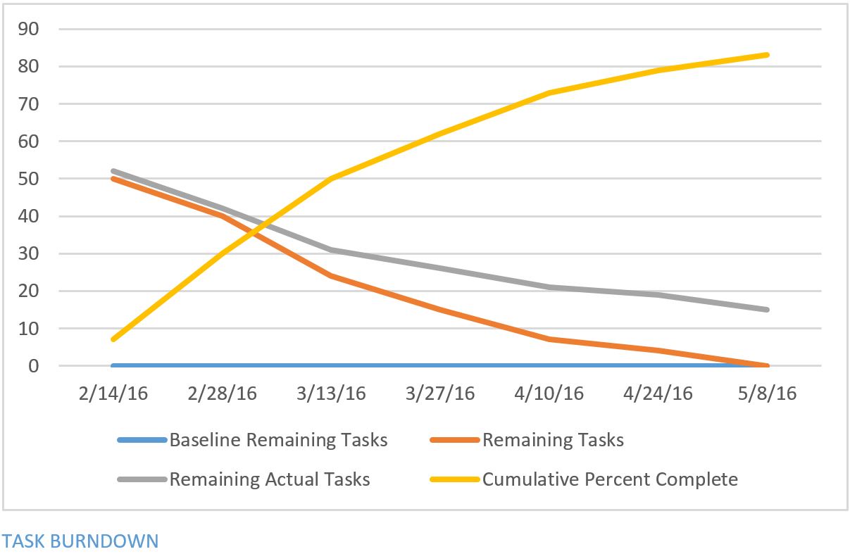
Completion
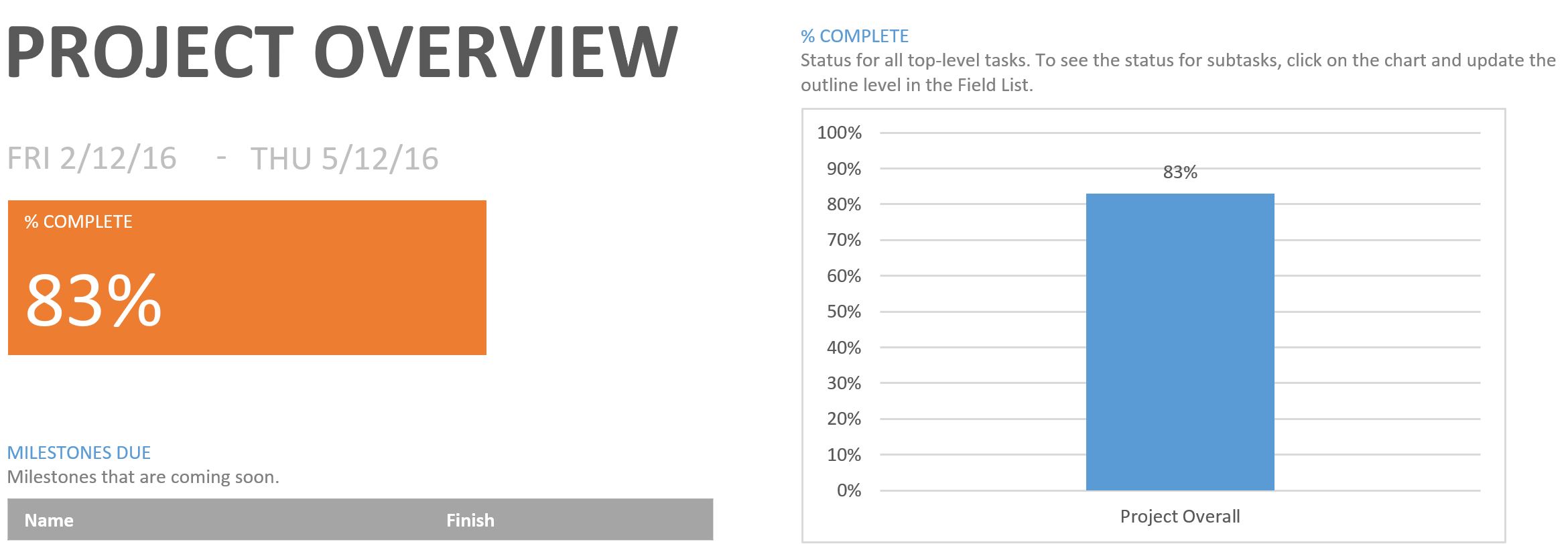
The Project Overall completion is 83%.
Concluding Thoughts:
Lessons learned the hard way
- The major problem our Pathfinder Team had was Project Tango. It is fairly new and has many limitations on sensor abilities as well. After we done the research of project tango, we realized that it requires extensive knowledge of Java programming and Android App development to accomplish the mission. Unfortunately none of the team member had that experience.
- The second issue we had was that the project requirements kept changing during the beginning of the semester. The mission profile went from daytime at desert terrain to night time at CSULB campus. The is due to the fact that the tango’s IR sensors for depth perception is generally restricted to indoor environments (sun and incandescent IR light can drown out structured light sensing).
- The third issue we had was that the manufacturing process for the aluminum sheets took too long from the rough cutting to mill finish. The aluminum was cut by hand by group members that weren’t supposed to be involved. As the project manager, I decided to let the the whole team contribute on assembling the parts during the final week to accomplish the mission. But the downside was that we did not have enough time to redo some of the verification tests for new chassis and motors.
- It is hard to manage the conflicts among cost, schedule and performance. Our pathfinder team was having trouble on getting all the parts we wanted. We were approved to get an extra budget of $300, yet, we still did not have enough money to get better wheels. The wheels problem lowered our project performance on obstacle climbing test.
Future Plans for Pathfinder
- Keep working on Project Tango. It is recommended to have 1 or 2 team members who has good knowledge of Android App development or some students from computer science major who can commit to help this project.
- The experimental results in this blog post need to be updated.
- The Mass and Power report need to be updated.
- Change the wheels on the pathfinder.
- Improve the encasement for tango (sealed, waterproof). This pathfinder can be taken to the wild area.
- Think of a way to rearrange the weight on top of the pathfinder. One issue we had was that the weight distribution was more on the backside, therefore it gives unstableness when climbing the obstacles.
Future Plans for project manager
- I think the project manager needs to be trained on their project management skills. Learning how to manage the cost, schedule and performance. A good way is to have a guest speaker give a short lecture on that.
- Project manager should post a project update blog post every two weeks. It can help them to keep on track of the project progress and schedules. It is also Easy for team member to follow.
Project Resource Files
Verification and Validation Documents